
Amplifier Circuit
Index 58
Two-road Output Voltage Regulating Circuit of LTC1702
Published:2011/9/13 5:44:00 Author:Michel | Keyword: Two-road Output, Voltage Regulating Circuit
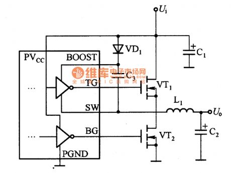
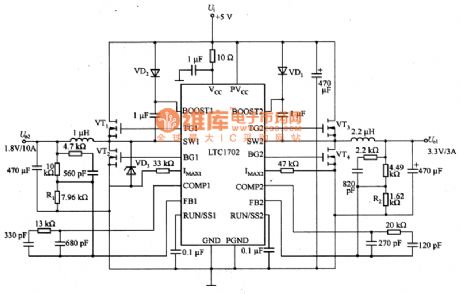
The picture a and b are two-road output voltage regulating circuit of LTC1702.There are two independent switch power controllers in LTC1702 and each controller uses external N channel MOSFET as power switch.It uses as synchronous step-down voltage circuit of voltage feedback function and it is shown as picture (a).VD1 and C3 are charging pump circuit and it makes the power supply voltage rise.The switch frequency is set to 550 kHZ and user programmable current limiting circuit uses synchronization MOSFET switch tube VT2 as current sensitive components.But small external resistance of current sensitive resistance can not be used.The design of switch voltage regulating circuit is different from the ordinary circuit design's.LTC1702 uses accurate 25 MHZ bandwidth gain operational amplifier as feedback amplifier,which uses best loop circuit as the compensating plan.This plan can also improve loop response.
(View)
View full Circuit Diagram | Comments | Reading(741)
LM1085 Low Voltage Margin Linearity and Stable Voltage Integrated Circuit
Published:2011/9/12 23:48:00 Author:Zoey | Keyword: Low voltage margin, linearity, stable voltage, integrated circuit,
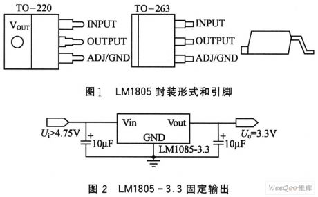
LM1085 is a typical stable voltage integrated circuit that has low voltage margin and linearity. Its input voltage margin can be as low as 1.5v, and output current can be 3A.
LM1085 can input fixed voltage and also can adjust output voltage by exterior resistances. Encapsulation style ones are TO-220 and TO-263, which can be seen in the picture 1 and 2 respectively.
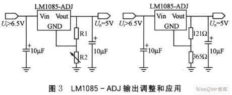
LM1085-ADJ belongs to input voltage and it can adjust integrated circuit of low voltage margin, the output ranges from 1.2~1.5V, which can be adjusted according to resistance value proportion of R1 to R2, as shown in picture 3.
In pratical, R1 is often fixed and R2 is adjustable. So, according to the formula:
Uo=VREF(1+R2/R1)+IADJR2
We can conclude following formula:
Uo=1.25 ·(1+R2/R1)
LM108x series have many types of integrated circuits, and their output current vary from one to another.
(View)
View full Circuit Diagram | Comments | Reading(0)
The driving circuit of the proportional electromagnet
Published:2011/9/12 21:50:00 Author:Ariel Wang | Keyword: driving, proportional electromagnet
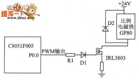
If you want to control the circuit,you can change duty ratio which is input to electrical signal of proportional electromagnet switch to realize controlling electric current. The more place the duty ration takes ,the faster of the controlling electric current goes through the coil of electromagnet.And the larger of the displacement . See chart 1 for the proportional electromagnet driveing circuit.
In driving circuit,R1 is current limiting resistor .It conducts IRL tube.D1 is a steering diode. It provides the right voltage direction for IRL3803 tube. Diode D2 is being the protective role.It avoids over voltage destroy proportional electromagnet.Proportional electromagnet is charged directly by 24V voltage.
(View)
View full Circuit Diagram | Comments | Reading(813)
Isolated Data Acquisition System Circuit composed by AD7714 and Microprocessor
Published:2011/9/13 6:48:00 Author:Vicky | Keyword: Isolated Data Acquisition, Microprocessor
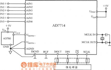
The above picture is a isolating data acquisition made up of five-channel low-dissipation programmable sensor signal processor AD7714 and micro-processor. AD7714 is available in low-dissipation narrow-bandwidth, and high-resolution data acquisition system. Three-line serial interface enables the data acquisition system to realize isolating by only three optical couplers. If input signals from AD7714 analog input end are positive, then the whole system canuse a single-power-supply of +3V or +5V. (View)
View full Circuit Diagram | Comments | Reading(1160)
HA1392 audio power amplifier circuit diagram
Published:2011/8/25 7:41:00 Author:Nancy | Keyword: audio, power amplifier
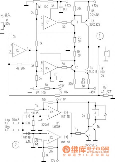
The circuit is shown as above, IC1 and T1, IC2 and T2 form the current negative feedback absorption constant current source respectively, which are the voltage,the current transition and amplification of the the positive half cycle and negative half cycle of the audio signal, which makes that the base current of T3 and T4 is only controlled by the input voltage of IC1 and IC2, in other words, once the the op-amp input is a constant voltage value, the current which flows throught the collector current of the final stage transistor is also a constant value.The W1, W2 (multiturn potentiometer) are respectively used to adjust the static current and output zero of T3 and T4, and the IC3 and R1, R2, R5 form the quasi current negative circuit, as long as you change the corresponding resistance value of R3, R4 or R2, R6, you can change the value of the gain. (View)
View full Circuit Diagram | Comments | Reading(3488)
TDA1514 (40W+40W)amplifier circuit
Published:2011/8/25 7:41:00 Author:Nancy | Keyword: amplifier
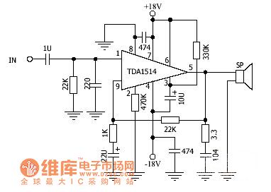
The TDA1514 is a sound special circuit designed to adapt to the high fidelity requirement of power amplifier for the digital sound, which is a 9-pin mono channel power amplifier integrated circuit with single package structure. Because of the use of advanced integration technology, the TDA1514 has some distinctive characteristics such as high output power, small distortion, wide frequency response and reliable performance etc.The TDA1514 is built with internal overheating protection and on-off noise suppression function, the static noise time is decided by an external circuit. (View)
View full Circuit Diagram | Comments | Reading(5742)
Pulse drive circuit
Published:2011/9/9 1:02:00 Author:John | Keyword: Pulse drive
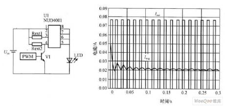
Figure shows the current waveform by pulse drive. The peak pulse drive current is about 4 times of the average current. The frequency is 100Hz and the duty cycle is 10%. This drive method has following advantages. As LED does not work most of the time in a cycle (90% of the cycle), the LED's heat is not necessary to be considered. Together with the reduction of the heat, LED’s light failure can be greatly reduced, thus extending the life of the LED. Therefore, the pulse-driven approach can be considered to be the most practical way for LED.
(View)
View full Circuit Diagram | Comments | Reading(976)
Half-bridge power conversion circuit
Published:2011/9/9 1:02:00 Author:John | Keyword: Half-bridge power conversion
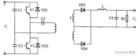
Half-bridge power conversion circuit can solve the imbalance for a push-pull power conversion circuit without any additional complexity for the circuit. Figure shows the half-bridge power conversion circuit. Just as the figure shows, one end of the power transformer primary winding is connected in series with the midpoint of capacitors C1 and C2 in the half-bridge power conversion circuit. Due to the capacitor’s dividing effect. The other end of power transformer is connected to the emitter of power transistor V1 and phase collector of V2 through capacitor C3.
(View)
View full Circuit Diagram | Comments | Reading(984)
Bell generator circuit
Published:2011/9/9 2:28:00 Author:John | Keyword: Bell generator
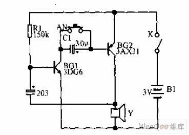
Bell generator’s deep and lingering bell can lead people into a profound mood. As shown in the circuit, AN is clicked to voice “dang” and the sound is prolonged until slowly weakening. R1 and C1 in the figure determine the tone of the oscillator. R1 can choose between the 50K ~ 500K and C1 can choose between 103 and 503.
(View)
View full Circuit Diagram | Comments | Reading(885)
P85C28OAER System Control Microcomputer Integrated Circuit
Published:2011/8/25 22:44:00 Author:Michel | Keyword: System Control , Microcomputer, Integrated Circuit
P85C28OAER is system control microcomputer integrated circuit which is widely used in control chip of color displays the Philips and Lenovo etc.
First,Function Features
P85C28OAER integrated circuit contains the I2C bus of large scale integrated circuit microcomputer.It not only has all kinds of analog control circuits, keyboard switch decoding circuit and kinds of distortion.It also tests contorl without siganls,saving energy control,memeory work means and other various auxiliary functions.
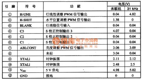
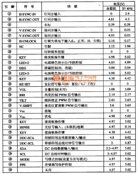
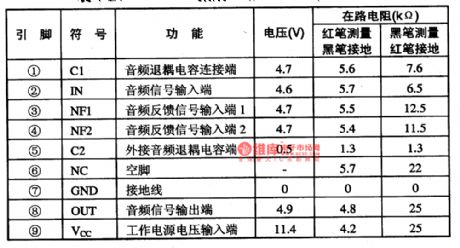
Second,Pins Fuctions and DataP85C280AER adopts feet 42 DIP package and its pins functions and data is shown as table 1.
Table 1:Pins Functions and Data ofP85C28OAER IC (View)
View full Circuit Diagram | Comments | Reading(712)
the expansion circuit of a 8-bits parallel port of PI port
Published:2011/8/11 4:01:00 Author:Ariel Wang | Keyword: expansion, 8-bits , parallel, port, PI
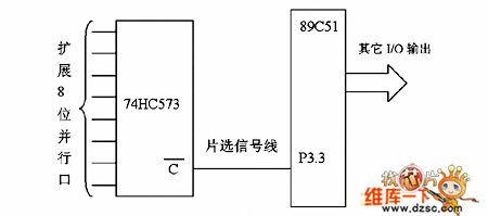
If there are toomany expansions and strobe signals take too many bits of parallel ports.For example,if you want to expand 8 parallel output ports.Then you need 8 signals.At this time,just these signals can take 8-bits parallel ports.Such huge resources wasting phenomena in singlechip system with limited I/O port linesare not tolerable.It adopts chip 74HC573( octal transparent type D flip-latch with three state output) to expand p1 port with 8-bits parallel port.Strobe signal adopts P3.3's pin of P3 port. The principle diagram is as seen as above.
(View)
View full Circuit Diagram | Comments | Reading(779)
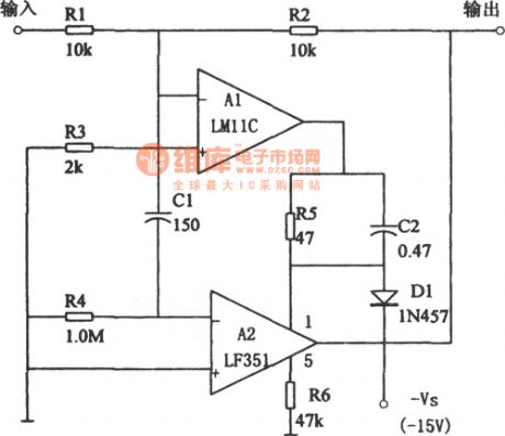
Current Follower Configuration Of High Precision And Low Bias(LM11,LF351)
Published:2011/9/6 4:46:00 Author:Felicity | Keyword: Current Follower Configuration, High Precision, Low Bias
View full Circuit Diagram | Comments | Reading(1254)
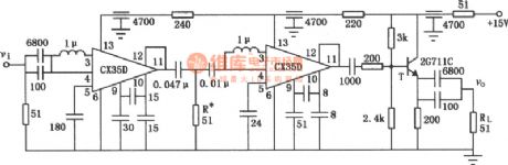
20MHz Low-noise Broadband Amplifier
Published:2011/9/6 4:47:00 Author:Felicity | Keyword: 20MHz, Low-noise, Broadband Amplifier
View full Circuit Diagram | Comments | Reading(835)
Space-saving HVArc Guard Capacitor goes for Passive Buffering Circuit
Published:2011/9/3 10:25:00 Author:Zoey | Keyword: Space-saving, HVArc Guard Capacitor, Passive Buffering
Many passive accessories can be used to make passive buffering circuits, and to absorb energy of reactance on switched circuits. Buffering circuits can pinchoff pulse noise, reduce power losses while cutting off circuits and reduce peak voltage on switches.
New HVArc Guard high pressure MLCC capacitor gathers the attributes such as high breakdown, low impedance, and wide work frequency scale together. What’s more, its size is as small as 0805.
HVArc Guard have excellent surge restrain capability. Here are the statistics for surge test on HVArc Guard capacitor.
C0G(N0P)HVArc Guard X7R HVArc Guard
1.2μs×50μs 1650V 500V
10μs×700μs 1800V 1200V
10μs×160μs >1500V 1200V
Following picture is an example for buffering circuit of totem pole MOSFET circuit. (View)
View full Circuit Diagram | Comments | Reading(695)
Infrared control automatic hand dryer (NE555, CD4069)
Published:2011/8/24 21:30:00 Author:Christina | Keyword: Infrared control, automatic, hand dryer
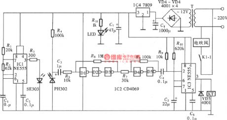
The automatic hand dryer is designed as one kind of high-grade sanitary that can be used in the bathroom of the hotel, airport, car station and stadium applications. The operating principle is to use the infrared control electronic switch, when someone's hand is closed, the infrared switch opens the electric blower automaticly, and when the hand leaves, it will close the electric blower automaticly. The automatic hand dryer integrated the infrared control switch and the electric blower, based on the basic principle, we can add the infrared control switch on the general electric blower to form a automatic hand dryer, the effect is the same as the automatic hand dryer.
(View)
View full Circuit Diagram | Comments | Reading(3055)
S1-3090C Controllable Voltage Regulator Circuit Diagram
Published:2011/9/3 21:34:00 Author:Zoey | Keyword: Controllable, Voltage Regulator
As a controllable voltage regulator integrated circuit, S1-3090C is widely used in audios, DVD players and so on. 1 Features S1-3090C IC consists of a+9 V voltage regulator circuit, a power on / off control circuit, and other auxiliary function circuits. 2 Pin functions and data S1- 3090C adopts pin-4single integrated circuit package,whichhasbeen used in Fine Refine King rear projection TVs,itspin functions of the integrated circuit and relevant data have been listed in Table 1.
(View)
View full Circuit Diagram | Comments | Reading(764)
AN5743 audio preamplifier and power amplifier integrated circuit
Published:2011/9/8 19:59:00 Author:Christina | Keyword: audio preamplifier, power amplifier, integrated circuit
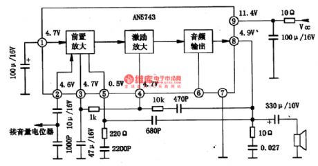
The AN5743 is designed as the audio preamplifier and power amplifier integrated circuit which is produced by the Panasonic company, and it can be used in all kinds of stereo systems.
1.The internal circuit block diagram and the functions of pin-5
The internal circuit of the AN5743 has the audio preamplifier, audio incentive and power amplifier functions. Also this circuit has the features of less external components, simple circuit structure. The internal circuit block diagram and the typical application circuit are as shown in figure 1-20. This IC uses the single row 9-pin package, the integrated circuit and data are as shown in table 1-21.
2.The typical application circuit of the AN5743
The typical application circuit of the AN5743 is as shown in figure 1-20.
3.Operating process (View)
View full Circuit Diagram | Comments | Reading(1375)
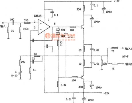
Broadband drive for capacitive load composed of LM6361
Published:2011/9/8 7:09:00 Author:Felicity | Keyword: Broadband drive, capacitive load
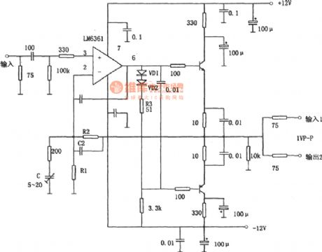
View full Circuit Diagram | Comments | Reading(1275)
Gain Programmable Amplifier Circuit
Published:2011/9/8 7:03:00 Author:Felicity | Keyword: gain programmable, amplifier

View full Circuit Diagram | Comments | Reading(890)
Circuit of gain programmable amplifier composed of OPA676
Published:2011/9/8 6:37:00 Author:Felicity | Keyword: gain programmable, amplifier
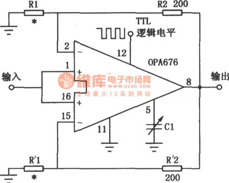
View full Circuit Diagram | Comments | Reading(687)
| Pages:58/250 At 204142434445464748495051525354555657585960Under 20 |
Circuit Categories
power supply circuit
Amplifier Circuit
Basic Circuit
LED and Light Circuit
Sensor Circuit
Signal Processing
Electrical Equipment Circuit
Control Circuit
Remote Control Circuit
A/D-D/A Converter Circuit
Audio Circuit
Measuring and Test Circuit
Communication Circuit
Computer-Related Circuit
555 Circuit
Automotive Circuit
Repairing Circuit