
Amplifier Circuit
Index 31
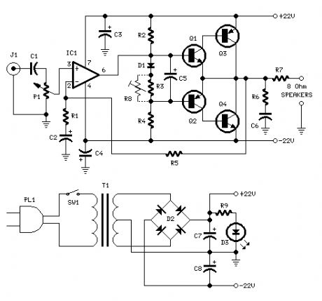
18W Audio Amplifier
Published:2012/12/19 21:28:00 Author:muriel | Keyword: 18W, Audio Amplifier
View full Circuit Diagram | Comments | Reading(758)
Preamp Circuit diagram
Published:2012/12/19 21:21:00 Author:muriel | Keyword: Preamp Circuit diagram
View full Circuit Diagram | Comments | Reading(982)
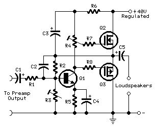
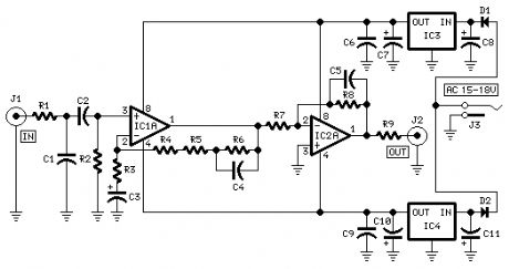
Mini-MosFet Audio Amplifier
Published:2012/12/19 21:21:00 Author:muriel | Keyword: Mini-MosFet, Audio Amplifier
View full Circuit Diagram | Comments | Reading(993)
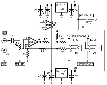
Modular Headphone Amplifier
Published:2012/12/19 21:18:00 Author:muriel | Keyword: Modular Headphone Amplifier
View full Circuit Diagram | Comments | Reading(1440)
Modular Phono Preamplifier
Published:2012/12/19 21:18:00 Author:muriel | Keyword: Modular Phono Preamplifier
View full Circuit Diagram | Comments | Reading(1064)
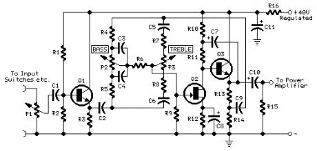
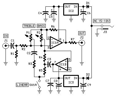
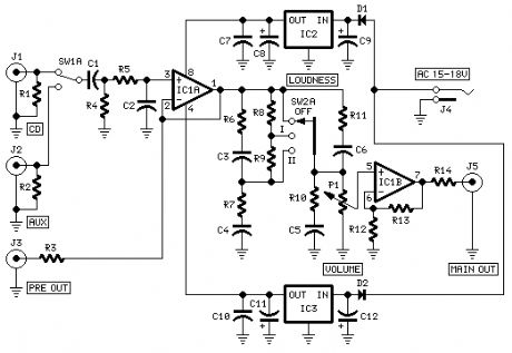
Modular Preamplifier Tone Control
Published:2012/12/19 21:17:00 Author:muriel | Keyword: Modular Preamplifier, Tone Control
View full Circuit Diagram | Comments | Reading(1189)
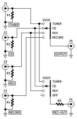
Modular Preamplifier Switching Center
Published:2012/12/19 21:16:00 Author:muriel | Keyword: Modular Preamplifier , Switching Center
View full Circuit Diagram | Comments | Reading(708)
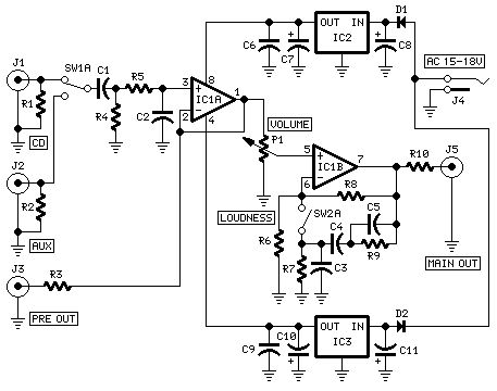
Modular Preamplifier Control Center II
Published:2012/12/19 21:15:00 Author:muriel | Keyword: Modular Preamplifier, Control Center II
View full Circuit Diagram | Comments | Reading(793)
Modular Preamplifier Control Center
Published:2012/12/19 21:15:00 Author:muriel | Keyword: Modular Preamplifier, Control Center
View full Circuit Diagram | Comments | Reading(848)
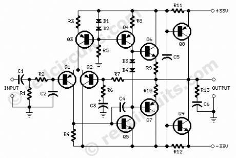
45 Watt Class B Amplifier
Published:2012/12/19 21:13:00 Author:muriel | Keyword: 45 Watt, Class B Amplifier
View full Circuit Diagram | Comments | Reading(1256)
High input impedance rapidly inverting amplifier circuit diagram
Published:2012/12/19 2:43:00 Author:Ecco | Keyword: High , input impedance, rapidly , inverting amplifier
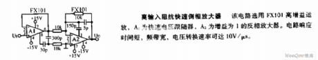
The circuit uses FX101 high gain op amp, A1 is a rapid voltage follower, A2 is an inverting amplifier with the gain of 1. The circuit response time is short, frequency bandwidth is wide, voltage slew rate is up to 10V/μs.
(View)
View full Circuit Diagram | Comments | Reading(785)
Basic feedback amplifier circuit diagram
Published:2012/12/19 2:40:00 Author:Ecco | Keyword: Basic feedback amplifier
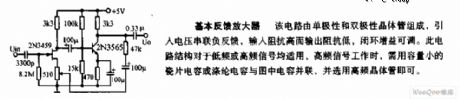
The circuit consists of unipolar and bipolar transistors, voltage isconnected to negative feedback in series, and input impedance is high while output impedance is low, and the closed-loop gain is adjustable. This circuit structure is applicable for low-frequency or high-frequency signals, when the high-frequency signal works,it requires ceramic capacitors or polyester capacitors with low capacity to connect to the capacitors shown in figure in parallel, and it selects high-frequency transistors.
(View)
View full Circuit Diagram | Comments | Reading(859)
Audio mixer amplifier circuit diagram
Published:2012/12/19 1:26:00 Author:Ecco | Keyword: Audio mixer amplifier
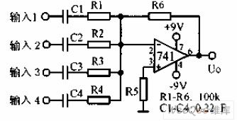
The audio mixer amplifier is a four-input audio mixer amplifier, and the output voltage is equal to the respective input signal. If the voltage gain is greater than 1, the value of R6 may be changed.
(View)
View full Circuit Diagram | Comments | Reading(1800)
The new electronic fractional frequency power amplifier circuit diagram
Published:2012/12/19 2:25:00 Author:Ecco | Keyword: electronic, fractional frequency, power amplifier
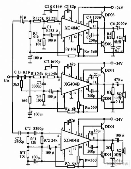
The circuit uses integrated power amplifier driver XG404. It can also achieve good characteristics of the filter divider while making power amplification, so it is a relatively ideal fidelity power amplifier. The rated output power without distortion ( harmonic distortion is less than 5% ) is 24W. The cutoff frequency on bass channel filter is 300Hz, C1 = 2C2 , C2 = 0.16μF, then R = 25KΩ, AU = ( R1 + RF ) / R1 = 100 ( FIG RF = 10KΩ , R1 = 100Ω ), and the cutoff frequency depends primarily on the coupling capacitor.
(View)
View full Circuit Diagram | Comments | Reading(1533)
AC amplifier circuit diagram to offset large DC offset
Published:2012/12/19 2:00:00 Author:Ecco | Keyword: AC amplifier , offset, large DC offset
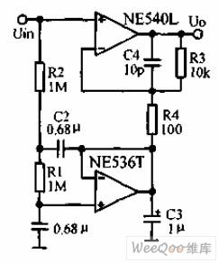
This circuit is used to amplify low VLF signals with high to 250KHz and a large dc component. The gain of amplifier NE540L is 101, NE536T's Merits stream gain is 1, and it constitutes a part of low-pass network which can connect the DC input offset voltage to the inverting input terminal of the gain amplifier as common voltage, thereby suppressing the DC offset.
(View)
View full Circuit Diagram | Comments | Reading(1452)
INA321/322 amplifier circuit diagram using feedback capacitor to improve dynamic characteristics
Published:2012/12/18 1:48:00 Author:Ecco | Keyword: amplifier , feedback capacitor , improve, dynamic characteristics
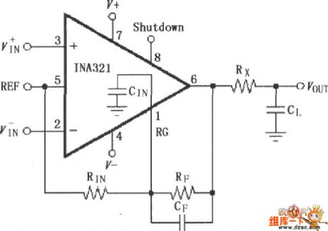
The both ends of the feedback resistor RF are connected to feedback capacitor CF in parallel, it is used to compensate for the feedback resistor, RG input equivalent capacitance and the effect on high - frequency signal from circuit board stray capacitance, so that the circuit has the best fast settling time. Output ( 6 feet ) end is connected to Rx, CL to reduce high-frequency noise, CIN is equal to INA321/322 input capacitance ( 3pF) and stray capacitance. RIN · CIN = RF · CF.
(View)
View full Circuit Diagram | Comments | Reading(1239)
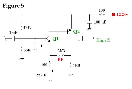
Low Power Popcorn Audio Power Amp 5
Published:2012/12/17 20:22:00 Author:muriel | Keyword: Low Power, Popcorn Audio, Power Amp 5
View full Circuit Diagram | Comments | Reading(733)
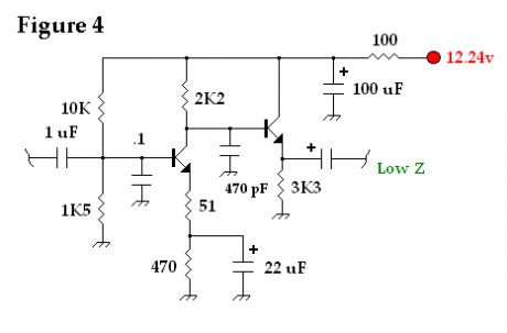
Low Power Popcorn Audio Power Amp 4
Published:2012/12/17 20:21:00 Author:muriel | Keyword: Low Power, Popcorn Audio, Power Amp 4
View full Circuit Diagram | Comments | Reading(694)
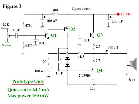
Low Power Popcorn Audio Power Amp 3
Published:2012/12/17 20:21:00 Author:muriel | Keyword: Low Power , Popcorn Audio, Power Amp 3
View full Circuit Diagram | Comments | Reading(755)
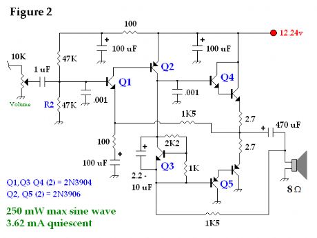
Low Power Popcorn Audio Power Amp 2
Published:2012/12/17 20:20:00 Author:muriel | Keyword: Low Power , Popcorn Audio , Power Amp
View full Circuit Diagram | Comments | Reading(1050)
| Pages:31/250 At 202122232425262728293031323334353637383940Under 20 |
Circuit Categories
power supply circuit
Amplifier Circuit
Basic Circuit
LED and Light Circuit
Sensor Circuit
Signal Processing
Electrical Equipment Circuit
Control Circuit
Remote Control Circuit
A/D-D/A Converter Circuit
Audio Circuit
Measuring and Test Circuit
Communication Circuit
Computer-Related Circuit
555 Circuit
Automotive Circuit
Repairing Circuit