
Index 313
Elliptic_filter_
Published:2009/7/24 12:53:00 Author:Jessie
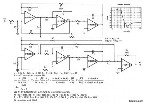
With the values shown, this circuit provides a 4th-order 1-kHz elliptic filter (with 4 poles and 4 zeros). The equations are given for other frequencies. Raytheon Linear integrated Circuits, 1989, p. 4-266. (View)
View full Circuit Diagram | Comments | Reading(1941)
Bi_quad_notch_filter
Published:2009/7/24 12:52:00 Author:Jessie
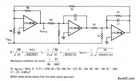
This circuit uses three sections of a quad op amp to form a notch filter. Circuit values are given for a 3-kHz notch with a Q of 5. The equations are given for other frequencies. Raytheon Linear integrated Circuits, 1989, p. 4-266. (View)
View full Circuit Diagram | Comments | Reading(925)
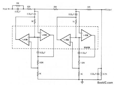
4_pole_Butterworth_filter
Published:2009/7/24 12:51:00 Author:Jessie
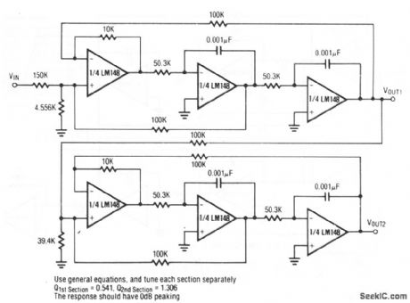
With the values shown, this circuit provides a 1-kHz 4-pole Butterworth filter function, with a direct-coupled input and outputs. Raytheon Linear integrated Circuits, 1989, p. 4-265. (View)
View full Circuit Diagram | Comments | Reading(1580)
Universal_state_space_filter
Published:2009/7/24 12:50:00 Author:Jessie
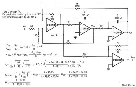
This circuit uses all four sections of a quad op-amp to form a universal state-space filter. Raytheon Linear integrated Circuits, 1989, p. 4-265. (View)
View full Circuit Diagram | Comments | Reading(793)
Dc_coupled_low_pass_active_filter
Published:2009/7/24 12:49:00 Author:Jessie
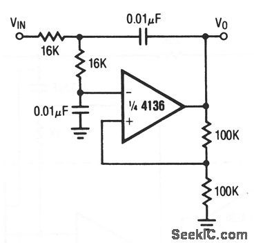
With the values shown, this circuit provides a 1-kHz low-pass filter function, with a direct-coupled input and output. Raytheon Linear integrated Circuits, 1989, p. 4-174. (View)
View full Circuit Diagram | Comments | Reading(734)
Low_pass_Butterworth_active_filter
Published:2009/7/24 12:48:00 Author:Jessie
With the values shown, this circuit provides a 400-Hz low-pass filter function. Raytheon Linear integrated Circuits, 1989, p. 4-172. (View)
View full Circuit Diagram | Comments | Reading(683)
Bi_quad_filter
Published:2009/7/24 12:46:00 Author:Jessie
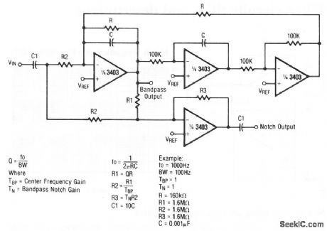
This circuit provides both a notch output and bandpass output. Raytheon Linear integrated Circuits, 1989, p. 4-161. (View)
View full Circuit Diagram | Comments | Reading(851)
LOW_FREQUENCY_LAMP_FLASHER_RELAY_DRIVER
Published:2009/6/30 2:45:00 Author:May
Circuit Notes
This circuit is a low frequency waming device. The output of the oscillator is a square wave that is used to drive lamps or small relays. The circuit altemately flashes two incandescent lamps. (View)
View full Circuit Diagram | Comments | Reading(660)
Multiple_feedback_bandpass_filter
Published:2009/7/24 12:45:00 Author:Jessie
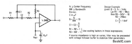
This circuit uses one section of a 3403 op amp with multiple feedback to form a bandpass filter. Raytheon Linear integrated Circuits, 1989, p. 4-160. (View)
View full Circuit Diagram | Comments | Reading(2545)
Notch_filter_using_an_op_amp_as_a_gyrator
Published:2009/7/24 12:44:00 Author:Jessie
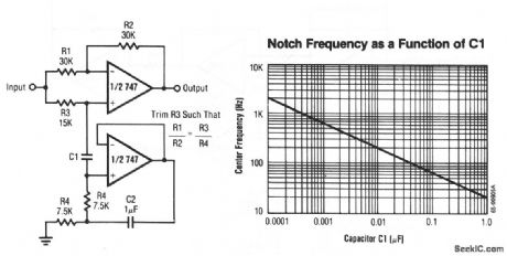
The center or notch frequency of this circuit is determined by the value of C1. Raytheon Linear integrated Circuits, 1989, p. 4-150. (View)
View full Circuit Diagram | Comments | Reading(975)
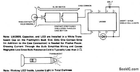
FLASHLIGHT_FINDER
Published:2009/6/30 2:44:00 Author:May
View full Circuit Diagram | Comments | Reading(603)
Simple_low_pass_filter
Published:2009/7/24 13:49:00 Author:Jessie
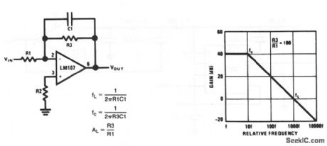
This circuit has a 6-dB per octave rolloff, after a closed-loop 3-dB point that is defined by fc(Fig. 7-41B). Gain below the fc corner frequency is defined by the ratio of R3 to R1. The circuit can be considered as an integrator at frequencies well above fc. However, the time-domain response is that of a single RC, rather than an integral. R2 should be chosen equal to the parallel combination of R1 and R3 to minimize bias-current errors. The op amp should be compensated for unity-gain, or an internally compensated op amp should be used. National Semiconductor, Linear Applications Handbook, 1991, p. 23, 24. (View)
View full Circuit Diagram | Comments | Reading(637)
Dc_accurate_low_pass_Bessel_filter
Published:2009/7/24 13:47:00 Author:Jessie
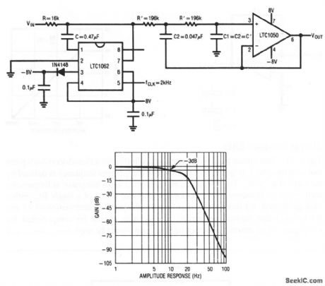
This circuit uses an LTC1050 and LTC1062 to form a low-cost 7th-order 10-Hz low-pass filter, where amplitude and phase response closely approximate a Bessel filter. The required clock frequency is 2 kHz, which yields a clock-to-cutoff frequency ratio of 200:1. Figure 7-40B shows the characteristics. Linear Technology, Linear Appications Handbook, 1990, p. DN9-1, -2. (View)
View full Circuit Diagram | Comments | Reading(1283)
8th_order_Chebyshev_bandpass_filter
Published:2009/7/24 13:46:00 Author:Jessie
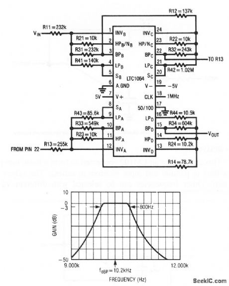
This circuit uses an LTC1064 switched-capacitor filter to form an 8th-order Chebyshev bandpass filter, with a center frequency of 10.2 kHz and a bandwidth of 800 Hz. Figure 7-39B shows the characteristics. Linear Technology, Linear Appications Handbook, 1990, p. AN27A-13, 15. (View)
View full Circuit Diagram | Comments | Reading(1208)
Low_pass_active_filter
Published:2009/7/24 13:44:00 Author:Jessie
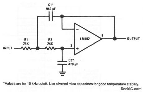
This circuit uses an LM102 connected to form a basic low-pass filter (input capacitors in parallel and input resistors in series). The values are for a 10-kHz cutoff. Other frequencies can be selected with different values. National Semiconductor, Linear Applications Handbook, 1991, p. 98. (View)
View full Circuit Diagram | Comments | Reading(1073)
High_pass_active_filter
Published:2009/7/24 13:41:00 Author:Jessie
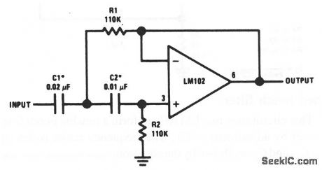
This circuit uses an LM102 connected to form a basic high-pass filter (input capacitors in series and input resistor in parallel). The values are for 100-Hz cutoff. Other frequencies can be selected with different values. National Semiconductor, Linear Applications Handbook, 1991, p. 98. (View)
View full Circuit Diagram | Comments | Reading(1705)
SCRATCH_FILTER_USING_LM387
Published:2009/6/30 2:36:00 Author:May
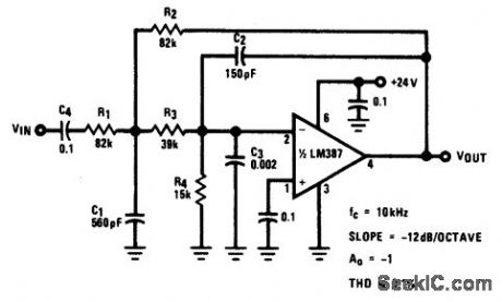
View full Circuit Diagram | Comments | Reading(684)
20_kHz_BANDPASS_ACTIVE_FILTER_
Published:2009/6/30 2:35:00 Author:May
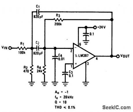
View full Circuit Diagram | Comments | Reading(619)
RUMBLE_FILTER_USING_LM387
Published:2009/6/30 2:34:00 Author:May
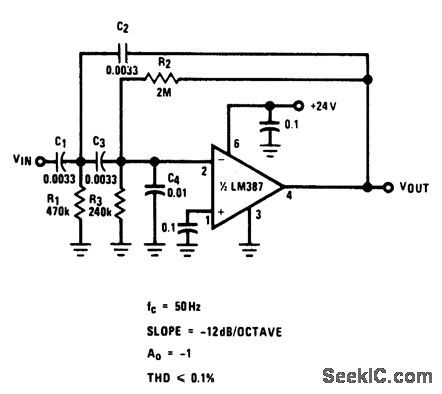
View full Circuit Diagram | Comments | Reading(716)
High_input_voltage_IC_filter
Published:2009/7/24 13:27:00 Author:Jessie
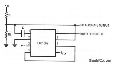

This circuit shows how an LTC1062 can be connected to accommodate high input voltages outside the normal input common-mode range. The dc gain of the low-pass filter is: R2/(R1 + R2). For maximum passband flatness, the paralleled combination of R1/R2 should be chosen as:
R1/R2≥ 5 kΩ. Notice that there is no need for an external op amp to buffer the divided-down input voltage. The internal buffer input (pin 7) performs this function. Linear Technology Corporation, Linear Applications Handbook, 1992, p. AN24-7.
(View)
View full Circuit Diagram | Comments | Reading(500)
| Pages:313/471 At 20301302303304305306307308309310311312313314315316317318319320Under 20 |
Circuit Categories
power supply circuit
Amplifier Circuit
Basic Circuit
LED and Light Circuit
Sensor Circuit
Signal Processing
Electrical Equipment Circuit
Control Circuit
Remote Control Circuit
A/D-D/A Converter Circuit
Audio Circuit
Measuring and Test Circuit
Communication Circuit
Computer-Related Circuit
555 Circuit
Automotive Circuit
Repairing Circuit