
Index 318
CONSTANT_AF_LEVEL
Published:2009/6/29 22:47:00 Author:May
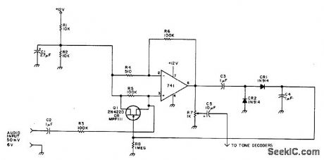
Provides constant output level even though input may vary between 50 mV and 6V, for distribution to tone decoders of autocall system used to monitor simplex or repeater channel to which amateur radio receiver is tuned. Positive terminal of electrolytic C3 must go to pin 6 of 741.-C.W.Andreasen, Autocall '76, 73 Magazine, June 1976, p 52-54. (View)
View full Circuit Diagram | Comments | Reading(2007)
COMPR_ESSOR_LIMITER
Published:2009/6/29 22:33:00 Author:May
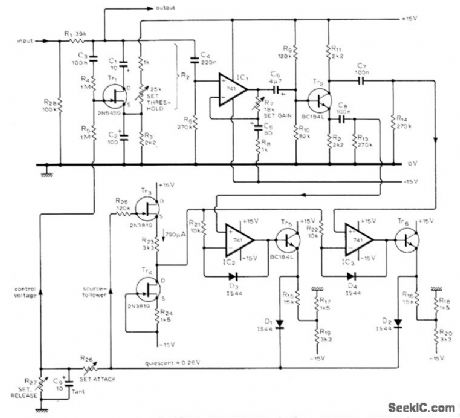
High-fidelity circuit uses voltage-controlled attenuator to increase attenuation of input signal in response to voltage of control loop. Designed for use in modern sound studios. Output-sensing amplifier using IC1 has gain of 19 over audio band. Tr2 stage is phase-splitterdriving precision rectifiers IC2 and IC3. Final part of circuit defines attenuation time constants; R26 sets attack time and R27 decay time. R26 can range from 0 to 1 megohm and R27 from 1000 ohms to infinity, using either switched or variable components. Article describes circuit operation and adjustment in detail. Tr6 is BC184L or equivalent.-D. R. Self, High-auality CompressoriLimiter, Wireless World, Dec. 1975, p 587-590. (View)
View full Circuit Diagram | Comments | Reading(809)
TWO_TUBE_WILLAMSON_OUTPUT
Published:2009/6/29 22:22:00 Author:May
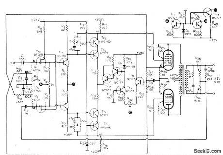
Responseis fiat from 10 Hz to over 50 kHz for outputs upto 15 W、and total harmonic distortion for full power output at 15 kHz is only 0.25%.Output stage uses tubes connected as triodes in pushpull. Input transistor can be any in Philips BFQ10-16 family or equivalent replacement such as Siliconix E401. Article gives many suitable replacements for other transistors as well, and describes desigit of required feedback cir-cuits in detail.-S. Berglund, Transistor Driver for Valve Amplifiers, Witeless World, April 1976, p 36-40. (View)
View full Circuit Diagram | Comments | Reading(1402)
BASS_BOOST
Published:2009/6/29 22:18:00 Author:May
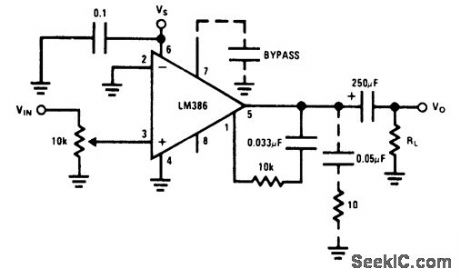
Compensates for poor bass response of loudspeaker by use of external series RC circuit between pins 1 and 5、paralleling internal 151k resistor of opamp.6-dB effective bass boost is obtained if resistor is 15K and lowest value for stable operation is 10k if pin 8 is left ope.- Audio Handbook, National Semiconductor,Santa Clara,CA,1977,p 4-30-4-33. (View)
View full Circuit Diagram | Comments | Reading(2269)
5_W_IC
Published:2009/6/29 22:06:00 Author:May
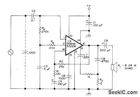
RCA IC includes preamps, power amplifier, and integral heatsink. CA3131 has internal feedback network that maintains 48-dB gain, while CA3132 requires external feedback network including R1 and R2 connected between pins 6 and 16. Input 1000-pF capacitor is required if input has open circuit. Electrolytic C1 should be placed as close as possible to pin 10,C6 sets 46-dB closed-loop gain pointat 200 kHz C7 equalizes gain for positive and negative signal swings C9 sets low-frequecy response of amplifier Recommended suppiv voltageis 24VDC,-E.Noll, Audio-Power Integrated Circults,Ham Radio、Jan 1976、p 64-66 (View)
View full Circuit Diagram | Comments | Reading(679)
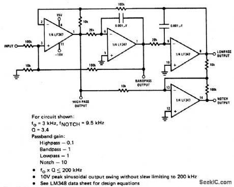
UNIVERSAL_STATE_VARIABLE_FILTER
Published:2009/6/29 21:51:00 Author:May
View full Circuit Diagram | Comments | Reading(0)
BANDPASS_STATE_VARIABLE_FILTER
Published:2009/6/29 21:50:00 Author:May
View full Circuit Diagram | Comments | Reading(685)
Current-voltage converter circuit
Published:2011/7/28 4:24:00 Author:John | Keyword: Current-voltage converter

Current-voltage converter circuit is shown.
(View)
View full Circuit Diagram | Comments | Reading(2664)
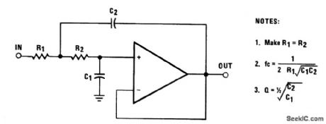
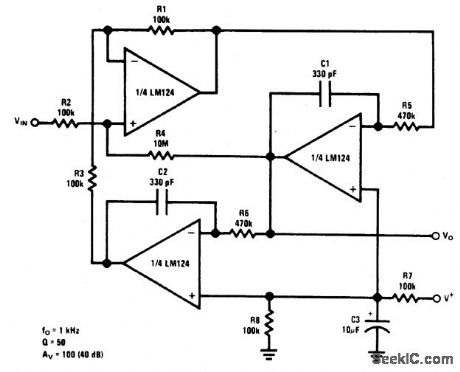
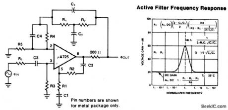
THREE_AMPLIFIER_ACTIVE_FILTER
Published:2009/6/29 21:48:00 Author:May
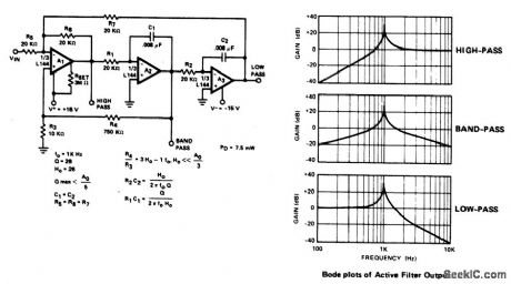
Circuit NotesThe active filter is a state variable filter with bandpass, high-pass and low-pass outputs, It is a classical analog computer method of implementing a filter using three amplifiers and only two capacitors. (View)
View full Circuit Diagram | Comments | Reading(1053)
SERIAL_DATA_OUTPUT
Published:2009/6/29 21:48:00 Author:May
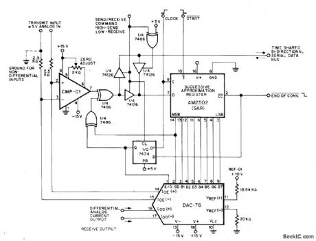
Precision Monolithics ICs form transceiving converter suitable for use in control systems incorporating 8-bit microprocessors. Output conforms whh Bell-System μ-255 logarithmic law for PCM transmission. Applications include servocontrols, stress and vibration analysis, digital recording, and speech synthesis. Start must be held low for one clock cycle to begin send or receive cycle. Conversion is completed in nine dock cycles, and output is available for one full clock cycle,Other half of system is identical.— COMDAC Companding D/A Convener, Precision Monolithics、Santa Clara、CA,1977、DAC-76、p 12 (View)
View full Circuit Diagram | Comments | Reading(1160)
SALLEN_KEY_SECOND_ORDER_LOW_PASS_FILTER
Published:2009/6/29 21:47:00 Author:May
View full Circuit Diagram | Comments | Reading(677)
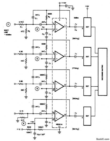
MFB_BANDPASS_FILTER_FOR_MULTICHANNEL_TONE_DECODER
Published:2009/6/29 21:44:00 Author:May
View full Circuit Diagram | Comments | Reading(700)
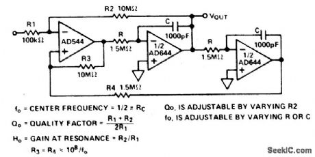
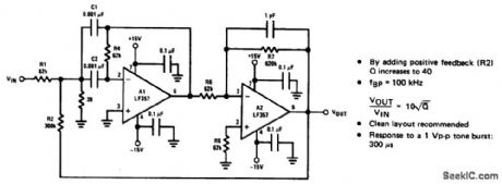
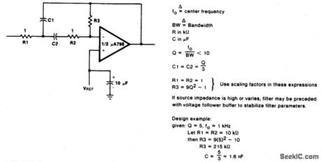
HIGH_Q_BANDPASS_FILTER
Published:2009/6/29 21:41:00 Author:May
View full Circuit Diagram | Comments | Reading(0)
LOW_PASS_FILTER
Published:2009/6/29 21:40:00 Author:May
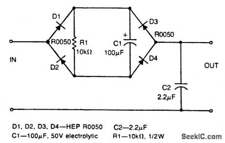
Circuit Notes
This nonlinear, passive filter circuit rejects ripple (or unwanted but fairly steady voltage) without appreciably affecting the rise time of a signal. The circuit works best when the signal level is considerably lower than the unwanted ripple, provided the ripple level is fairly constant. The circuit has characteristics similar to two peakdetecting sample-and-hold circuits in tandem with a voltage averager. (View)
View full Circuit Diagram | Comments | Reading(131)
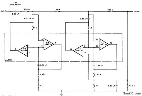
VARIABLE_BANDWIDTH_BANDPASS_ACTIVE_FILTER
Published:2009/6/29 21:36:00 Author:May

Circuit Notes
This circuit has adjustable bandwidthwith values for a center frequency of about 800 Hz. The10 K pot adjusts bandwidth from approximately ±350 Hz to ±140 Hz at 3 dB down points. (View)
View full Circuit Diagram | Comments | Reading(779)
400_Hz_LOW_PASS_BUTTERWORTH_ACTIVE_FILTER
Published:2009/6/29 21:34:00 Author:May
View full Circuit Diagram | Comments | Reading(600)
BIQUAD_RC_ACTIVE_BANDPASS_FILTER
Published:2009/6/29 21:30:00 Author:May
View full Circuit Diagram | Comments | Reading(811)
MULTIPLE_FEEDBACK_BANDPASS_FILTER
Published:2009/6/29 21:28:00 Author:May
View full Circuit Diagram | Comments | Reading(0)
BANDPASS_ACTIVE_FILTER_WITH_60_dB_GAIN
Published:2009/6/29 21:27:00 Author:May
View full Circuit Diagram | Comments | Reading(811)
Language Analysing Polygraph Circuit
Published:2011/7/20 3:52:00 Author:Joyce | Keyword: Language, Analysing, Polygraph
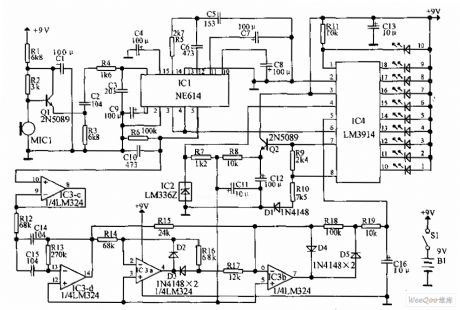
The signal of M1C1 is coupled to NE *, and signal RSSI output by feet 5 of logarithmic amplifiers IC1, IC1 is buffered by IC3-C of the op-amp LM324 to drive IC3-d, IC3-a, IC3-b to compose a detector for all wave crests. When output of IC3 = b is positive, the signal is integrated by R19 and C16. When language is stopped or the speaker is under great pressure, voltage of C16 will discharges through R18 and R19, for the time constant of C16 and R18, R19 is larger. It can make the bar chart DISP1 display signals which are increasing rapidly. During the suspension of language processing, a slow discharge will keep the value at display.
(View)
View full Circuit Diagram | Comments | Reading(1767)
| Pages:318/471 At 20301302303304305306307308309310311312313314315316317318319320Under 20 |
Circuit Categories
power supply circuit
Amplifier Circuit
Basic Circuit
LED and Light Circuit
Sensor Circuit
Signal Processing
Electrical Equipment Circuit
Control Circuit
Remote Control Circuit
A/D-D/A Converter Circuit
Audio Circuit
Measuring and Test Circuit
Communication Circuit
Computer-Related Circuit
555 Circuit
Automotive Circuit
Repairing Circuit