
Index 304
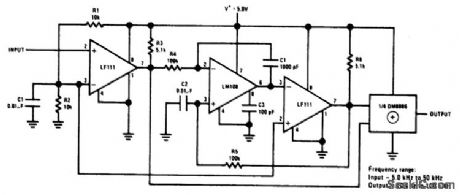
FREQUENCY_DOUBLER
Published:2009/7/1 2:32:00 Author:May
View full Circuit Diagram | Comments | Reading(2246)
PROGRAMMABLE_VOLTAGE_CONTROLLED_FREQUENCY_SYNTHESIZER
Published:2009/7/1 2:32:00 Author:May
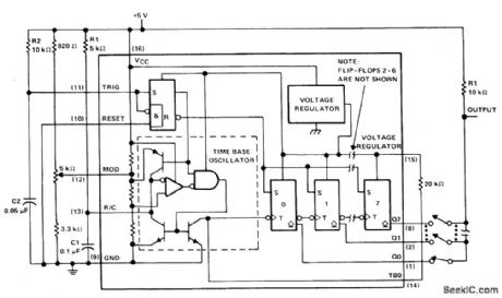
The μA2240 consists of four basic circuit elements: (1) a time-base oscillator, (2) an eight-bit countqr, (3) a control flip-flop, and (4) a voltage regulator. The basic frequency of the time-base oscillator (TBO) is set by the external time constant determined by the values of R1 and C1 (R1C1 = 2 kHz). The open-collector output of the TBO is connected to the regulator output via a 20 k ohm pull-up resistor, and drives the input to the eight-bit counter. At power-up, a positive trigger pulse is detected across C2 which starts the TB0 and sets all counter outputs to a low state. Once the μA2240 is initially triggered, any further trigger inputs are ignored until it is reset. In this astable operation, the μA2240 will free-run from the time it is triggered until it receives an external reset signal. Up to 255 discrete frequencies can be synthesized by connecting different counter outputs. (View)
View full Circuit Diagram | Comments | Reading(597)
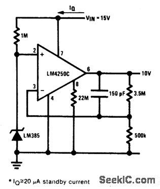
PRECISION_REFERENCE_MICROPOWER_10_V_REFERENCE
Published:2009/7/1 2:30:00 Author:May
View full Circuit Diagram | Comments | Reading(514)
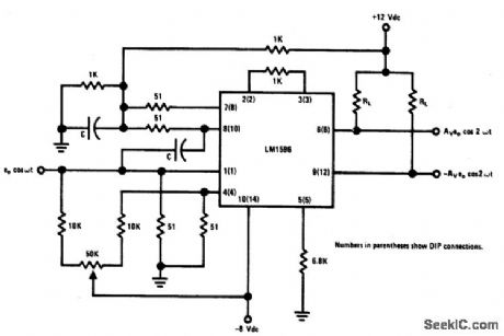
BROADBAND_FREQUENCY_DOUBLER
Published:2009/7/1 2:29:00 Author:May
Circuit Notes
This circuit will double lowlevel signals with low distortion. The value of C should be chosen for low reactance at the operating frequency. Signal level at the carrier input must be less than 25 mV peak to maintain operation in the linear region of the switching differential amplifier. Levels to 50 mV peak may be used with some distortion of the output waveform. If a larger input signal is available, a resistive divider may be used at the carrier input with full signal applied to the signal input. (View)
View full Circuit Diagram | Comments | Reading(981)
High_resolution_continuous_output_sampled_bridge
Published:2009/7/24 5:28:00 Author:Jessie
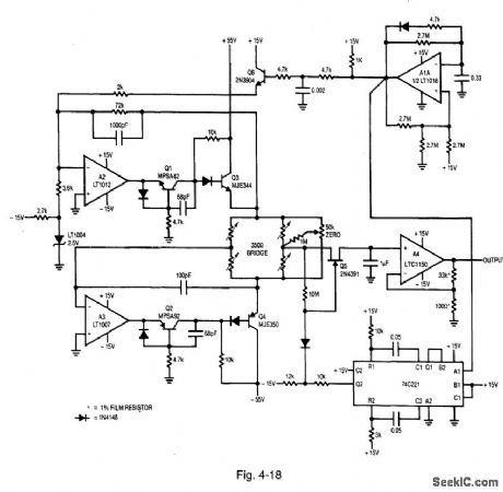
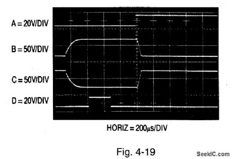
Figure 4-18 shows a sampled bridge with continuous output and high resolution.Figure 4-19 shows the waveforms. Traces A, B, C, and D show the A1A output, Q3 emitter, complementary output to A2 loop, and the 74C221 delayed pulse to Q5.The circuit applies 100 V across a 10-V, 350-0 strain-gauge bridge for short periods of time. The high pulsed-voltage drive increases bridge output proportionally, without forcing excessive dissipation. The average bridge power is far below the normal 29 mA obtained with the usual 10-Vdc excitation. Combining the 10× higher bridge gain (300 mV full-scale versus the normal 30 mV) with a chopper-stabilized amplifier in the sample-hold output stage is the key to the high resolution. To calibrate, simply adjust the 50-kΩ zero control for zero output with the bridge at mechanical zero. Although the output is continuous, information is collected at a 1-Hz rate, and the Nyquist limit applies when interpreting results. LINEAR TECHNOLOGY, APPLICATION NOTE 43, P. 23. (View)
View full Circuit Diagram | Comments | Reading(644)
Continuous_output_sampled_bridge
Published:2009/7/24 5:23:00 Author:Jessie
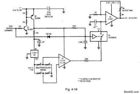
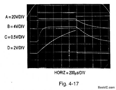
Figure 4-16 shows a bridge signal conditioner with sampled continuous output.Figure 4-17 shows the waveforms. Traces A, B, C, and D show the Q2 collector, LT1021-5 output, A1 output, and S1 input, respectively. The output is made continuous by the addition of a sample-hold stage. Q2 is off when the sample command is low. Under these conditions, only A2 and S1 receive power, resulting in a current drain of less than 60 μA. When the sample command is pulsed high, the Q2 collector (trace A, Fig. 4-17) goes high, providing power to all other circuit elements. During the sampling phase, supply current approaches 20 mA, but a 10-Hz sampling rate cuts effective drain below 250 μA. Slower sampling rates will further reduce drain, but the C1 droop rate (about 1 mV/100 ms) sets the accuracy constant. The 10-Hz rate provides adequate bandwidth for most transducers. For 3-mV/V-slope-factor transducers, the gain trim shown (1 M) allows proper calibration. It might be necessary to rescale the gain trim for other transducer types. The A2 output is accurate enough for 12-bit systems. Although the output is continuous, information is collected at a 10-Hz rate, and the Nyquist limit applies when interpreting the results. LINEAR TECHNOLOGY, APPLICATION NOTE 43, P. 21. (View)
View full Circuit Diagram | Comments | Reading(695)
AC_LINE_OPERATED_UNIJUNCTION_METRONOME
Published:2009/7/1 2:27:00 Author:May
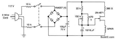
The UJT-oscillator frequency is determined by the 100μF capacitor and the effective resistance of the 22 K and 470 K resistors and the potentiometer. Rate can be varied from 42 to 208 beats/minute. The circuit should be housed in an insulated box for safety, or use ground (3-wire cord). (View)
View full Circuit Diagram | Comments | Reading(693)
CIRCUIT_FOR_MULTIPLYING_PULSE_WIDTHS
Published:2009/7/1 2:27:00 Author:May
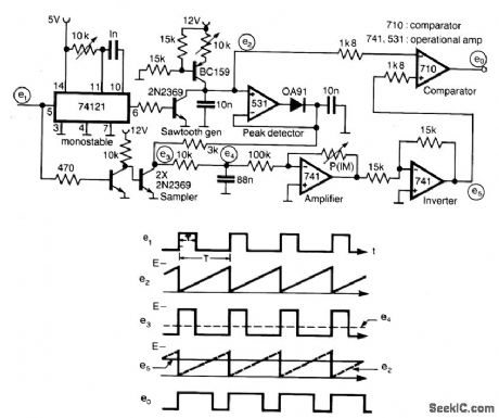
A circuit for multiplying the width of incoming pulses by a factor greater or less than unity is simple to build and has the feature that the multiplying factor can be selected by adjusting one potentiometer only. The multiplying factor is determined by setting the potentiometer P in the feedback of a 741 amplifier. The input pulses e1 of widthT and repetition period T is used to trigger a sawtooth generator at its rising edges to produce the waveform e2 having a peak value of (E) volt. This peak value is then sampled by the input pulses to generate the pulse train e3 having an average value of e4(=E ET/T) which is proportional to Tand independent on T. The dc voltage e4 is amplified by a factor k and compared with sawtooth waveform e4 giving output pulses of duration k T. The circuit is capable of operating over the frequency range 10 kHz - 100 kHz. (View)
View full Circuit Diagram | Comments | Reading(759)
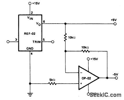
±_5_V_REFERENCE
Published:2009/7/1 2:26:00 Author:May
View full Circuit Diagram | Comments | Reading(553)
METRONOME_I
Published:2009/7/1 2:26:00 Author:May
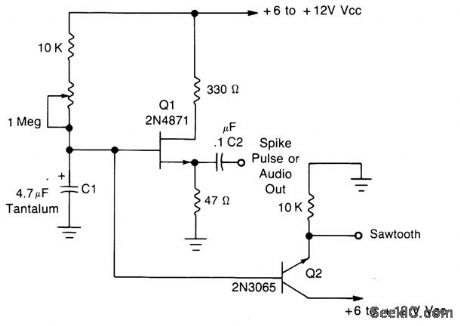
This simple oscillator uses a 2N4871 UJT to give pulses from 0.2 to about 20 Hz.A spike is available at C2, a sawtooth at the emitter of Q2 of about 2-3 V p-p, depending on VCC. (View)
View full Circuit Diagram | Comments | Reading(1086)
SIMPLE_METRONOME
Published:2009/7/1 2:25:00 Author:May
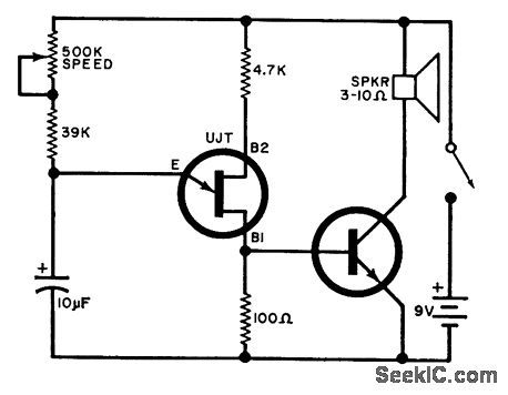
Adjustable from 15 to 240 beats per minute. The UJT oscillator output is applied to a general purpose npn transistor which drives the speaker.UJT=2N4871NPNxistor=TIP31 (View)
View full Circuit Diagram | Comments | Reading(2807)
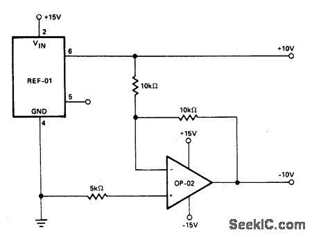
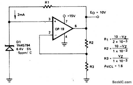
±_10_V_REFERENCE
Published:2009/7/1 2:25:00 Author:May
View full Circuit Diagram | Comments | Reading(548)
METAL_LOCATOR
Published:2009/7/1 2:24:00 Author:May
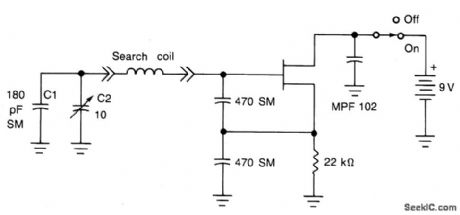
The search coil, C1 and C2 form a tuned circuit for the oscillator which is tuned near the center of the broadcast band. Tune a portable radio to a station near the middle of the band, then tune C2 until a squeal is heard as the two signals mix to produce a beat (heterodyne) note. Metal near the search coil will detune the circuit slightly, changing the pitch of the squeal. The search coil is 20 turns of number 30 enameled wire, wound on a 6 x 8 wood or plastic form. It is affixed at the end of a 30 to 40 wooden or plastic pole, and connected to the remainder of the metal detector circuit through a coaxial cable. (View)
View full Circuit Diagram | Comments | Reading(1883)
METAL_LOCATOR_Ⅱ
Published:2009/7/1 2:23:00 Author:May
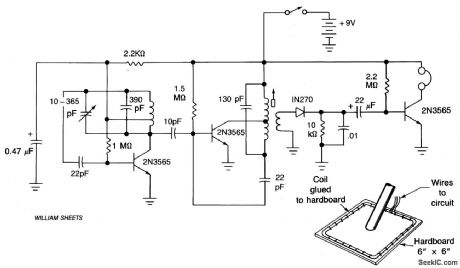
The circuit consists of two oscillators, both working at about 465 kHz. One uses an if transformer and the other uses an inductor (the search coil L1). The oscillators are coupled by a capacitor (10 pF). A beat note (produced if the two oscillators are working closely together) is detected by the diode and fed to the headphone amplifier and the 22μF capacitor. The search coil oscillator is tuned by a 10-365 pf variable capacitor.The search coil comprises 22 turns of wire (any gauge between 24 swg and 36 swg enamel) center tapped. The wire should be wound on a temporary form then taped and glued to a piece of hardboard. The coil size should be about 6 x 6 . Headphones should be high impedance. (View)
View full Circuit Diagram | Comments | Reading(1450)
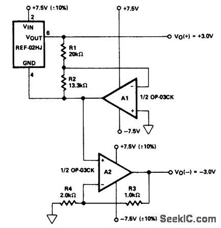
±_3_V_REFERENCE
Published:2009/7/1 2:23:00 Author:May
View full Circuit Diagram | Comments | Reading(530)
MEDICAL_INSTRUMENT_PREAIVIPLIFIER
Published:2009/7/1 2:22:00 Author:May
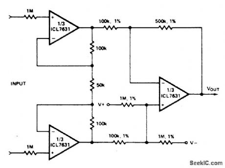
Note that AVOL=25; single Ni-cad battery operation. Input current (from sensors connected to the patient) is limited to less than 5μh under fault conditions. (View)
View full Circuit Diagram | Comments | Reading(565)
12_V_AUTO_CLOCK
Published:2009/7/1 2:21:00 Author:May
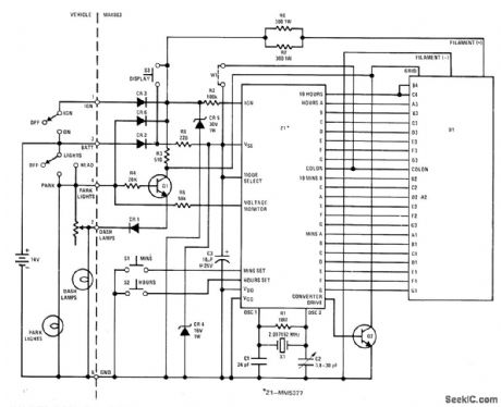
National MA1003 automotive/instrument clock module combines MM5377 MOS LSI clock with 4-digit 0.3-inch green vacuum fluorescent display,2.097-MHz crystal, and discrete components on single printed-circuit board to give complete digital clock. Brightness control logic blanks display when ignition is off, reduces brightness to 33% when parking or headlight lamps are on, and follows dash-lamp dimming control setting.Display has leading- zero blanking. For portable applications, display can be activated by closing display switch momentarily,- MOS/LSI Data-book, National Semiconductor, Santa Clara, CA, 1977, p 13-8-13-10.
(View)
View full Circuit Diagram | Comments | Reading(5341)
HIGH_STABILITY__VOLTAGE_REFERENCE
Published:2009/7/1 2:21:00 Author:May
View full Circuit Diagram | Comments | Reading(592)
QUARTZ_MOTOR_WRISTWATCH
Published:2009/7/1 2:19:00 Author:May

Uses one 32.768-kHz crystal at input of Motorola MTD 160F or 161F custom CMOS chip,Mith stepper motor at output of chip fordriving conventional watch hands. Chip contains three-inverter oscillator, 16 counting flip-flops, and motor drive buffers.-B. Furlow, CMOS Gates in Linear Applications: The Results Are Surprisingly Good, EDN Magazine, March 5, 1973, p 42-48. (View)
View full Circuit Diagram | Comments | Reading(750)
MAKING_SLOW_LOGIC_PULSES_AUDIBLE
Published:2009/7/1 2:18:00 Author:May
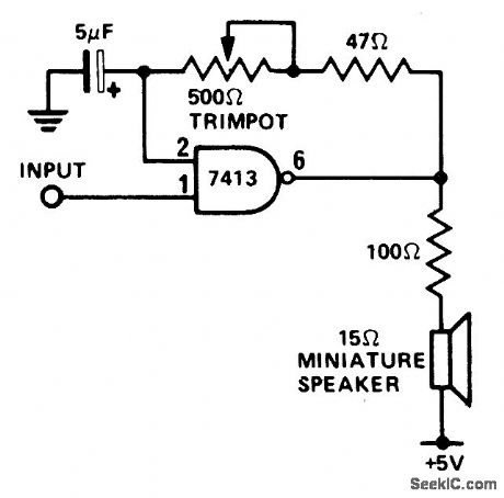
This circuit is useful for monitoring slow logic pulses as a keying monitor or digital clock alarm. The Schmitt trigger is connected as an oscillator. The trimpot controls the pitch of the output. When the input goes high, the circuit will oscillate. (View)
View full Circuit Diagram | Comments | Reading(572)
| Pages:304/471 At 20301302303304305306307308309310311312313314315316317318319320Under 20 |
Circuit Categories
power supply circuit
Amplifier Circuit
Basic Circuit
LED and Light Circuit
Sensor Circuit
Signal Processing
Electrical Equipment Circuit
Control Circuit
Remote Control Circuit
A/D-D/A Converter Circuit
Audio Circuit
Measuring and Test Circuit
Communication Circuit
Computer-Related Circuit
555 Circuit
Automotive Circuit
Repairing Circuit