
Index 202
The automatic door control circuit diagram with infrared sensor IC WT8075
Published:2011/5/13 4:29:00 Author:Ecco | Keyword: automatic door, control circuit , infrared sensor, IC

The circuitry is shown as below: It includes pyroelectric infrared sensor head, infrared sensor control circuit, SCR control circuit, music sound circuit and exchange step-down rectifier circuit, etc. (View)
View full Circuit Diagram | Comments | Reading(3396)
Infrared sensing automatic startup control circuit diagram with SR5553
Published:2011/5/13 4:29:00 Author:Ecco | Keyword: Infrared sensing automatic startup control
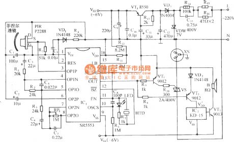
The circuitry shows as below: It includes pyroelectric infrared sensor head, infrared sensor control circuit, SCR control circuit, music sound circuit and exchange step-down rectifier circuit, etc. This control circuit can be used as control of automatic fan boot, automatic, energy-saving lamps, security, automatic interpretation etc. Pyroelectric infrared sensor head includes pyroelectric infrared sensor P2288 and the Fresnel optical lenses. The latter connects the infrared radiation that is from human body energy, to improve the detection range. The Fresnel lens have all sorts of different specifications, common have Q - 6 type, Q1A type and Q - 8 type, etc. To make energy‘s largest gathered, it requests lens face and infrared sensors to keep a certain distance, to different lens, their spotlighting distance is different. The reasonable configuration and installing can make detection distance be improved greatly. P2288 will detect the infrared radiation that from the pedestrians, then make impedance matching and magnifiing by the filter, signal mosfet (FET), emitted by source S to the signal input (IC1 OP1P) pin 3. (View)
View full Circuit Diagram | Comments | Reading(1671)
3 different ways of driving high-power control circuit diagram
Published:2011/5/17 4:11:00 Author:Ecco | Keyword: 3 , different ways , driving , high-power, control circuit
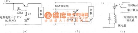
The figure shows the 3 different ways of driving high-power control circuit. Flashing light-emitting diodes can be used as high-power multi-center load control circuit devices to drive a variety of incandescent light flashes. Figure (a) uses high-power transistor to drive circuit; Figure (b) uses high-power bidirectional thyristor to controll driver circuit; Figure (C) uses relay to control the load. VT can choose 3AD, 3CD PNP power transistor. SCR can also use one-way, but the load current is pulsating DC current. The load of the 3 circuits flashes intermittently under the control of light-emitting diode.
(View)
View full Circuit Diagram | Comments | Reading(533)
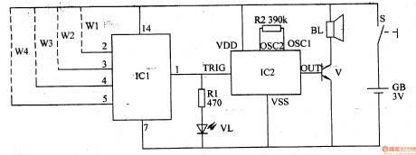
CPU fan stopping alarm circuit diagram
Published:2011/6/24 4:17:00 Author:Ecco | Keyword: CPU , fan , stopping alarm
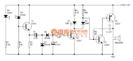
D1 and D2 are respectively the infrared transmitter and infrared receiver tubes, and they are against the installation and 1.2-1.8 cm apart. When it gets power, D1 emits a continuous infrared beam IR, which is intermittently hitting the receiver tube under the block of blade from time to time. This, V1 will have a pulse type of bias current to make the two ends of R2 generate pulse voltage. D4 must use a germanium diode such as 1N60, 2AP9 and so on. SPEAKER can select the type on the quartz clock with pointer.
(View)
View full Circuit Diagram | Comments | Reading(1628)
The timer with definite time opening and closing and automatic circulation function circuit diagram
Published:2011/6/30 1:32:00 Author:Rebekka | Keyword: definite time opening and closing , automatic circulation function
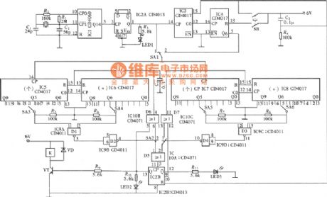
This circuit is a quartz crystal type high precision adjustable timer. It is set by the gears switch time function selection choose and timing. The timing time setting range is 0 ~ 99 s or 0 ~ 99 min. The circuit is shown in figure. The circuit is composed of seconds time, scheduled power circuit, timing boot circuit, regular shutdown circuit, timing cycle control circuit and execution of circuit. (View)
View full Circuit Diagram | Comments | Reading(729)
The temperature control switch circuit of Nanjing Iveco light car
Published:2011/7/12 7:59:00 Author:Borg | Keyword: temperature control, light car
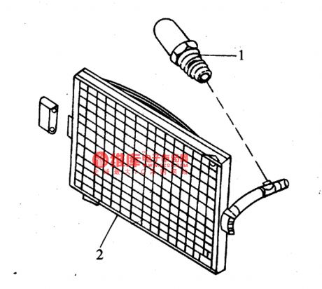
(17)The temperature control switch of the cooling fan (see as figure 19)
(View)
View full Circuit Diagram | Comments | Reading(662)
Cycle timer with open and stop preset function circuit diagram
Published:2011/6/29 4:14:00 Author:Rebekka | Keyword: Cycle timer, preset function
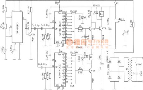
This circuit is a cycle timing controller composed of 555 time base circuit. The time base signals outputed by 555 circuit passes the frequency demultiplication of the digital circuits and gets multi-stage timing control output. It passes the cooperation of the relay, and forms the preset boot, preset shutdown automatic cycle time controller. Its circuit is shown in figure. (View)
View full Circuit Diagram | Comments | Reading(1971)
KA5L0380——the switch power supply integrated circuit
Published:2011/7/13 11:34:00 Author:Borg | Keyword: switch power supply, integrated circuit
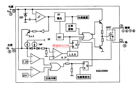
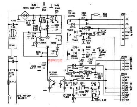
KA5L0380R is a single chip switch power supply integrated circuit of current mode, which is used in DVD players.1.the internal circuitKA5L0380R contains crystal clock circuit, power clamp sampling gating circuit, 5V regulated circuit, internal bias circuit, logic circuit, current limit circuit, over-voltage/current/heat and low voltage protection circuit, whose internal circuit is shown in figure 1-1.
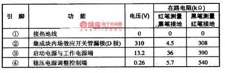
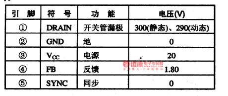
2.pin functions and dataKA5L0380R is packaged in two ways, on of them is 4-pin TO-220F type.
(View)
View full Circuit Diagram | Comments | Reading(4582)
gas flame extinguishment alarm(II)
Published:2011/7/14 20:51:00 Author:chopper | Keyword: gas extinguishment
This example describes the gas flame extinguishment alarm,it can monitor the gas stoves,gas heaters and other gas instruments that use gas.And once gas flame accidentally goes out,the alarm will immediately send an alarm to alert the user to process. Principle of the circuit The gas flame extinguishment alarm circuit includes the flame monitoring control circuit and sound alarm circuit,which is shown in figure 6-205.
(View)
View full Circuit Diagram | Comments | Reading(912)
gas flame extinguishment alarm(I)
Published:2011/7/14 20:51:00 Author:chopper | Keyword: gas extinguishment
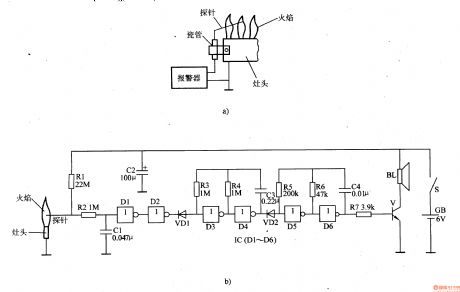
This example describes the gas flame extinguishmentalarm, and it can send a alarm when the gas flame turns off accidentlly,and notice the users,in order to eliminate hidden security trouble. Principle of the circuitThe gas flame extinguishment alarm circuit includes flame detection circuit,amplification shaping circuit,2Hz ultra-low-frequency oscillator,lkHz pulse oscillator and audio amplifier output circuit, just as 6-204 shows.
(View)
View full Circuit Diagram | Comments | Reading(3656)
infant quilt-kicking,bed-wetting alarm
Published:2011/7/14 20:49:00 Author:chopper | Keyword: quilt-kicking, bed-wetting
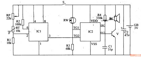
This example describes the infant quilt-kicking,bed-wetting alarm,which can send the heat preservation caution when the infant kicks the quilt;and it can send the pay attention to changing diapers alarm when infant wets the bed,and it is suitable for home and nursery. The principle of circuitThe infant quilt-kicking,bed-wetting alarm circuit is formed by temperature detection control circuit,bed-wetting detection circuit and alarm circuit,which is shown in figure 6-190. Temperature detection control circuit is formed by the thermistor RT,resistors Rl,R2,potentiometer RP and time-base integrated circuit IC1.
(View)
View full Circuit Diagram | Comments | Reading(1577)
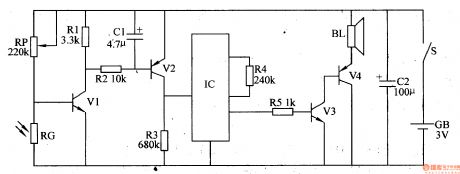
infant quilt-kicking alarm(2)
Published:2011/7/14 20:49:00 Author:chopper | Keyword: quilt-kicking
This example describes the infant quilt-kicking alarm,which is mainly formed by the non-door digital IC and music integrated circuit. It can monitor the quilt situation,and senda acoustic and optical alarm signal in time to inform parents when the baby kicks quilt.
The principle of circuit
This infant quilt-kicking alarm circuit is formed by monitor circuit and sound and light alarm circuit, which is shown in figure 6-189.
(View)
View full Circuit Diagram | Comments | Reading(554)
agricultural non-tower pressure-charged water feeder (4)
Published:2011/7/14 20:49:00 Author:chopper | Keyword: non-tower, pressure-charged
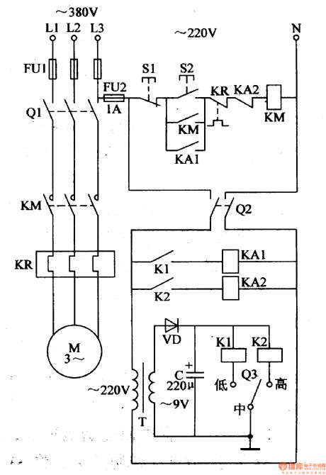
The principle of circuit This agricultural non-tower pressure-charged water feeder circuit is formed by power supply circuit and pressure measurement control circuit, as shown in figure 4-155. Power supply circuit is formed by the fuse FU2,knife switch Q2,the power transformer T,the rectifier diode VD and filter capacitor C. Pressure measurement control circuit is formed by the electric connecting pressure gauge Q3,relays K1,K2,intermediate relays M1,KA2,AC contactor KM,thermal relay KR,control buttons S1,S2,and knife switch Q1.
(View)
View full Circuit Diagram | Comments | Reading(631)
agricultural non-tower pressure-charged water feeder(3)
Published:2011/7/14 20:49:00 Author:chopper | Keyword: non-tower, pressure-charged
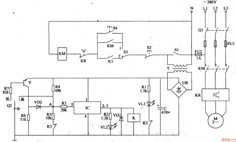
The principle of circuit This agricultural non-tower pressure-charged water feeder circuit is formed by the power supply circuit, pressure detection circuit,control circuit and indication circuit, which is shown in figure 4-154. Power supply circuit is formed by the knife switch Q1,fuses FU1,FU2 power transformer T,bridge rectifier UR and filter capacitor C. Detection circuit is formed by the electric connecting pressure gauge Q2,resistors R4-R7,normal closed contact K3 of relay K and the transistor V.
(View)
View full Circuit Diagram | Comments | Reading(836)
CMOO2lAF--the concentrating adjustment control integrated circuit
Published:2011/7/13 19:45:00 Author:Borg | Keyword: concentrating adjustment, integrated circuit
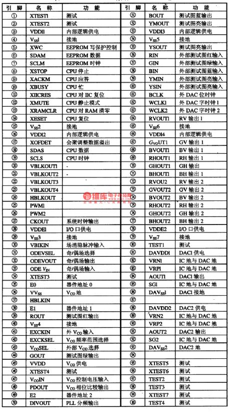
1.function featuresCMOO2lAF contains all types of waveform generators, dynamic concentration and sawtooth generating D/A converter, digital signal process circuit, I and C general connector, transverse/longitudinal control circuit, PWN waveform and clock control circuit for coarse-tuning and fine-tuning. It characterizes high precision(16-bit), high adjusting speed, auto regulation, support of many scanning formats(line frequency range:15.5KHz~48KHz) and so on.2.pin functions CMOO2lAF is in 100-pin QFP plastic package, whose pin functions are listed in table 1.
(View)
View full Circuit Diagram | Comments | Reading(535)
brake lamp delay arrester
Published:2011/7/12 22:30:00 Author:chopper | Keyword: brake lamp, delay arrester
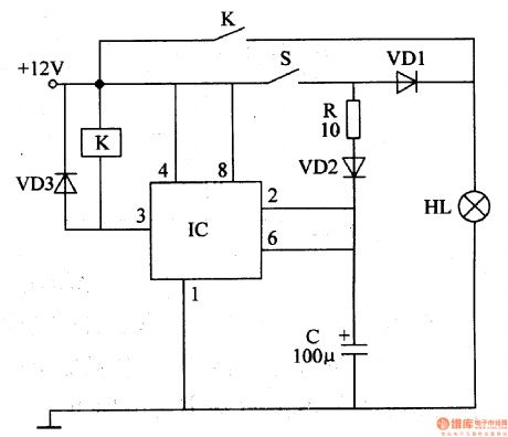
Brake lamp of general motor will light when the brake switch is trampled,and it will extinguish immediately when the brake switch is released.This example describes the brake lamp delay arrester, which can make brake lamp light for some time before it gose out when the brake switch is released,and it can avoidthe vehicle rear-end collision efficiently,and increase traffic safety. The principle of circuitThis brake lamp delay arrester includes time-base integrated circuit IC,relay K,capacitor C and diode VD1-VD3,which is shown as figure 7-34.
(View)
View full Circuit Diagram | Comments | Reading(661)
KA3S0880RFB--the thick film integrated circuit of the switch power supply
Published:2011/7/13 20:04:00 Author:Borg | Keyword: thick film, integrated circuit, power supply
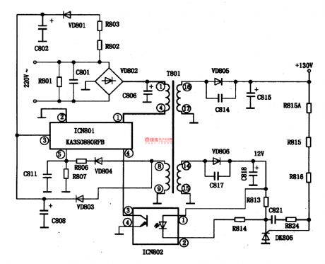
KA3S0880RFB is a thick film integrated circuit of the switch power supply produced by Samsung, which is widely used in Hisense interaction large color TV sets, etc.1.function featuresKA3S0880RFB contains sub-circuits of oscillating, synchronization and over-current/voltage/heat protection circuit, whose typical application circuit is shown in figure 1-1.
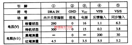
2.pin functions and dataKA3S0880RFB is in single 5-pin in-line package, whose pin functions and data are listed in table 1-1.
Table 1-1. pin functions and data of KA3S0880RFB (View)
View full Circuit Diagram | Comments | Reading(886)
KA3S0680R--the switch power supply thick film integrated circuit
Published:2011/7/13 20:11:00 Author:Borg | Keyword: switch power supply, thick film, integrated circuit
KA3S0680R is a switch power supply thick film integrated circuit produced by Samsung, which is widely used in Haier-Gaomei large screen color TV sets, such as GBTV-29FA RGBTV-29TA, 29F18 and so on.1.function featuresKA3S0680R contains the switch pipe, switch pipe motivation amplifier circuit, fault detection signal process circuit, synchronous signal process circuit and other additional circuits.2.pin functions and dataKA3S0680R is in 5-pin single in-line package, whose pin functions and data are listed in table 1-1.
(View)
View full Circuit Diagram | Comments | Reading(677)
phone off-hook reminder
Published:2011/7/12 0:33:00 Author:chopper | Keyword: phone, off-hook, reminder
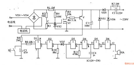
Fixed phone users may not hang up the telephone receiver well and effect the phone call after using the phone.This example describes the phone off-hook reminder,and it can not only send a sound beep to remind the user of hanging up the phone in time, but also has the role of telephone line anti-theft alarm. Principle of the circuitThis phone off-hook reminder includes supply power circuit,phone line monitoring circuit,and sound alarm circuit and so on,just as picture 6-206 shows.
(View)
View full Circuit Diagram | Comments | Reading(1164)
telephone on-hook reminder(II)
Published:2011/7/12 0:24:00 Author:chopper | Keyword: telephone, on-hook, reminder
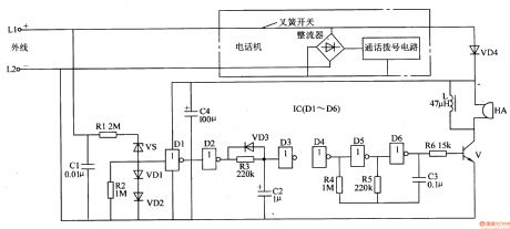
This example describes telephone on-hook reminder,and it can send a sound di when the telephone is on-hook to tell the users that the telephone has been hung up. Principle of the circuit This telephone on-hook reminder circuit includes trigger circuit,inverter,delay circuit,audio oscillator and audio output circuit,just as picture 6-207 shows. (View)
View full Circuit Diagram | Comments | Reading(550)
| Pages:202/312 At 20201202203204205206207208209210211212213214215216217218219220Under 20 |
Circuit Categories
power supply circuit
Amplifier Circuit
Basic Circuit
LED and Light Circuit
Sensor Circuit
Signal Processing
Electrical Equipment Circuit
Control Circuit
Remote Control Circuit
A/D-D/A Converter Circuit
Audio Circuit
Measuring and Test Circuit
Communication Circuit
Computer-Related Circuit
555 Circuit
Automotive Circuit
Repairing Circuit