
Index 211
The auto switch of the TV sound emitter
Published:2011/7/10 8:54:00 Author:Seven | Keyword: auto switch, sound emitter
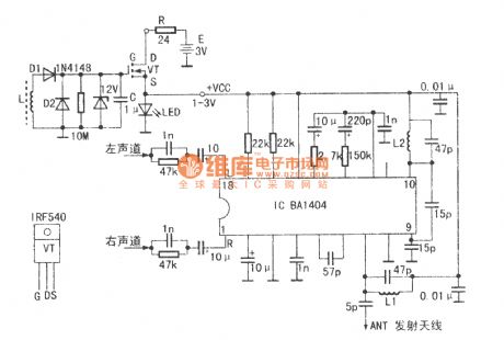
See as the figure, the main circuit is an ordinary single chip FM stereo broadcast emitter integrated circuit BA1404, whose circuit is well known. Both L1 and L2 are covered by the enameled wire of 0.3mm, 5 turns in total. The internal diameter is 3mm, the length is 8mm. With the coil winded according the data, the frequency is 10MHz. In the received range of ordinary radios. The auto part is in the left-upper part of the figure, whose principle is that after the TV set is turned on, there generates a strong magnetic field which is produced by the line scanning system of the tube in the TV set. (View)
View full Circuit Diagram | Comments | Reading(739)
Three-phase motor using the relay to prevent phase short circuit switching circuit
Published:2011/7/9 22:58:00 Author:Lucas | Keyword: Three-phase motor, relay
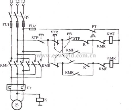
Just shown in the figure, a relay K is used to connect its coil to the main road. If the primary contact’s adhesion primary live line is with electricity or arc is not extinguished, K pulls to drive the normally closed contacts K to cut off STF and STR loop. So no matter what the forward or reverse button is pressed, the motor can not be started.
(View)
View full Circuit Diagram | Comments | Reading(1387)
The SXTY 3-phase AC booster (closed loop) trigger board circuit
Published:2011/7/10 9:08:00 Author:Seven | Keyword: 3-phase, AC booster, trigger board
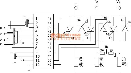
SXTY 3-phase AC booster (closed loop) trigger boards are used in 3-phase AC booster systems as the trigger unit of the SCR, the trigger plate includes the synchronized single detection, closed loop PI regulator and pulse transformer output unit. It can compose the 3-phase AC booster system with the function of voltage regulating output. SXTY 3-phase AC booster plate technology parameters. 1. AC input voltage: dual 18V (AC, 50Hz); input current ≤200 mA; 2.the regulated working voltage range of the main circuit: 380V (AC, 50Hz);3.3-phase synchronized signal input range.
(View)
View full Circuit Diagram | Comments | Reading(4463)
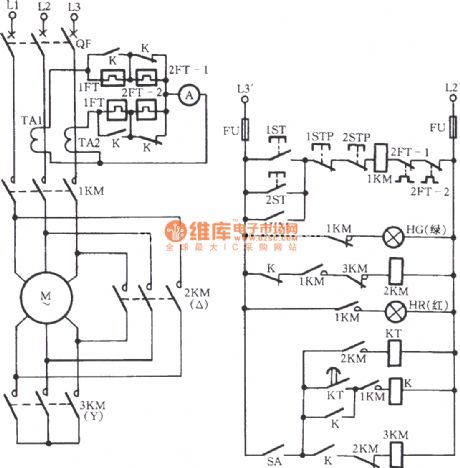
Three-phase motor button and contactor dual-interlock switching circuit
Published:2011/7/9 11:17:00 Author:Lucas | Keyword: Three-phase motor, button, contactor, dual-interlock
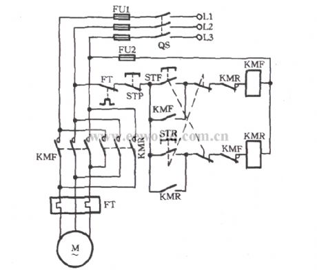
Button contactor dual-interlock switching circuit is shown in the figure, which integrates the advantages of the button interlock and the contactor interlock.
(View)
View full Circuit Diagram | Comments | Reading(3081)
The 8-line interlock switch circuit
Published:2011/7/10 9:32:00 Author:Seven | Keyword: interlock switch
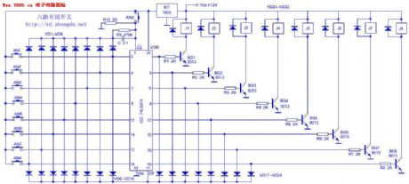
The circuit working principle The power supply of the circuit is 12V, which is regulated by IC1(7805) and turned into the 5V power supply. IC2 and the external elements compose the 8-line interlock circuit, the relay J1~J8 compose the switch executing components. The pins of IC2 is marked in the figure. The 1-pin EN is the power terminal, low LEV is effective, so the 1-pin is connected with the earth directly. D1~D8 are the trigger terminals, CP is the clock terminal, Q1~Q8 are the output terminals. When AN1~AN8 are pressed in sequence, the corresponding triggers D1~D8 and CP terminal are in high LEV. (View)
View full Circuit Diagram | Comments | Reading(1740)
The grid circuit of threshold switch
Published:2011/7/10 9:48:00 Author:Seven | Keyword: grid circuit, threshold switch
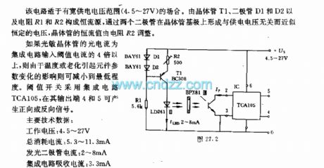
The circuit can be used in situations of wide power supply voltage range 4.5~27V. The constant source of transistor T1, diodeS D1 and D2, resistors R1 and R2 and so on. A voltage which is irrelevant to the power supply but has almost constant voltage is generated on the basic pole of 2 diodes, the constant current is regulated by the resistor R2. If the current of the light sensitive transistor is more than 4 times of the threshold, the effect on the elements caused by the temperature or aging can be minimized.
(View)
View full Circuit Diagram | Comments | Reading(745)
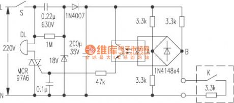
The intelligent control switch(with the time delay and anti-impact intelligent relay switch)
Published:2011/7/8 20:46:00 Author:Seven | Keyword: relay switch, intelligent control switch
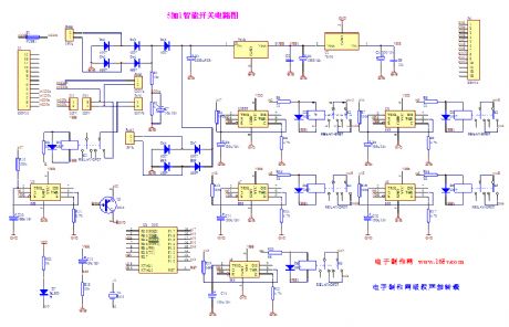
The intelligent control switch( with the time delay and anti-impact intelligent relay switch)
(View)
View full Circuit Diagram | Comments | Reading(747)
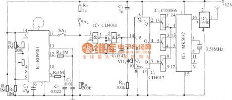
The multi-function alarm circuit composed of wireless receivers
Published:2011/7/10 10:08:00 Author:Seven | Keyword: multi-function alarm, wireless receivers
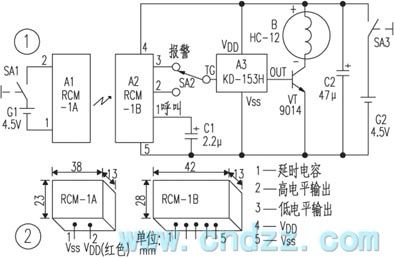
Working principles The circuit is shown in Figure 1, of which the wireless remote module A1 and battery G1, power supply SA1 compose the emitter; the wireless remote receiving module A2, analog sound integrated circuit A3 and so on compose the reception alarm.Usually, the aerial in A1 can emit the ultra-high magnetic wave of 250~300MHz into the around space, in the effective range, the wave is received by the micro reception aerial in module A2, and then it is modulated, amplified, detected, delayed and LEV converted by the internal circuit, finally, the pin outputs a low LEV.
(View)
View full Circuit Diagram | Comments | Reading(684)
The vibration inductance "monks chanting Buddhist scripts" circuit (LM386 and LH690)
Published:2011/7/10 10:17:00 Author:Seven | Keyword: vibration inductance, Buddhist scripts
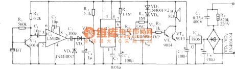
See as the figure, the circuit consists of the sensor, amplifier stage, rectifier circuit, single stable trigger circuit, monks chanting Buddhist scripts sound circuit and AC step-down rectifier circuit, etc. (View)
View full Circuit Diagram | Comments | Reading(735)
The finger touch high frequency photo/sound alarm circuit
Published:2011/7/8 20:29:00 Author:Seven | Keyword: high frequency, photo/sound alarm
See as the figure, the circuit consists of the touching power switch, SCR generating circuit, whistle sound making circuit and audio power amplifier circuit, etc. It can be used in banks and abodes as the emergency alarm. (View)
View full Circuit Diagram | Comments | Reading(668)
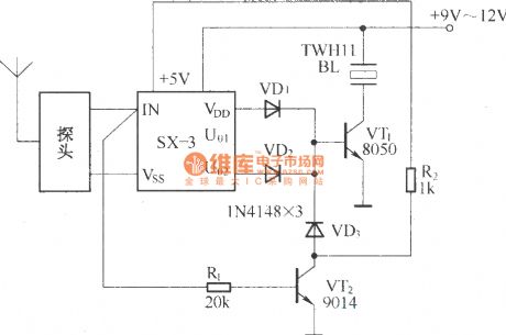
The alarm circuit composed of T630/T631
Published:2011/7/8 20:01:00 Author:Seven | Keyword: alarm circuit
The probe of the circuit is a microwave sensing module RD9481, which is encoded by DTMF(dual-audio multi-frequency), the transmission of the alarm signal and address is done by the long wave transceiver unit T630/T631, the circuit can display the alarm spot, so it is suitable for multi-channel (16) integrated monitor alarm system. The circuit consists of the host and the extension, apart from the different address encode, all the extension circuits are the same.Alarm host circuit:
Alarm extension circuit:
(View)
View full Circuit Diagram | Comments | Reading(891)
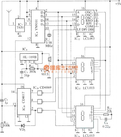
The remote alarm composed of SX-3
Published:2011/7/8 20:07:00 Author:Seven | Keyword: remote alarm
SX-3 human body inducting switch is a microwave control unit which works according to the Doppler effect, it is in a plate structure, the outline size is l00mm×50mm, its probe and signal processor can be divided into two parts, which is convenient to detect remotely, the circuit can be used in alarms, auto doors, auto lamps, auto audio control devices and so on. (View)
View full Circuit Diagram | Comments | Reading(657)
A durable alarm circuit
Published:2011/7/8 20:14:00 Author:Seven | Keyword: durable alarm
Many citizens have additional storerooms, as the storeroom is not at the same side with the living room, so it's not easy to realize when it is pried or the motor is stolen.Here is to introduce a storage door alarm, one wire of the alarm's is from the living room to the storeroom, as long as the owner close the door and turn on the alarm, whether it is pried or the external wire is cut off or short, the alarm will make the alarm sound.
(View)
View full Circuit Diagram | Comments | Reading(600)
three-phase motor with △-starting and Y-running circuit
Published:2011/7/9 10:55:00 Author:Lucas | Keyword: three-phase motor
View full Circuit Diagram | Comments | Reading(822)
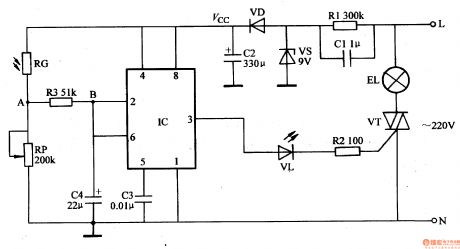
Light-Operated Streetlight (12)
Published:2011/7/1 6:14:00 Author:Sue | Keyword: Light-Operated, Streetlight
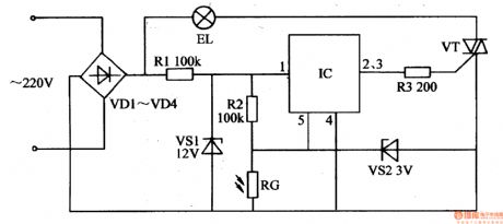
The 220v voltage will generate +12v voltage after reduction and stablization. The voltage will be put on IC. The other circuit will provide IC's pin 5 with voltage.
In the daytime, RG will have a low resistance value which will make IC's pin 5 have a low level. IC's inner switch will be disconnected. Its pin 2 and pin 3 will output low level and VT is disconnected. EL is not illuminated.
When it is dark, RG will have a high resistance value which will make IC's pin 5 have a high level. IC's inner switch will be connected. Its pin 2 and pin 3 will output high level. VT is connected and EL is illuminated. (View)
View full Circuit Diagram | Comments | Reading(558)
Light-Operated Streetlight (11)
Published:2011/7/1 6:09:00 Author:Sue | Keyword: Light-Operated, Streetlight
The 220v voltage will provide IC2 with working voltage after the reduction, rectification and filtration. The other circuit will provide the light-operated circuit with Vc voltage.
In the daytime, RG has a low resistance value because of the light. IC1's pin 2's working voltage is higher than 2Vcc/3. IC1's pin 3 will output low level which will make K connected. EL is not illuminated. At the same time, IC2's pin 3 will output high level which will make V2 connected. IC1's pin 2 will output low level. V2 is disconnected.
When it is dark, RG has a higher resistance value. IC1's pin 2's voltage will be lower. When pin 2's voltage is lower than Vcc/3, IC1's pin 3 will have a high level. K is released. V1 is connected. (View)
View full Circuit Diagram | Comments | Reading(557)
Light-Operated Streetlight (9)
Published:2011/7/1 5:57:00 Author:Sue | Keyword: Light-Operated, Streetlight
The 220v voltage will provide IC with 8.5v working voltage after reduction, stablization, rectification and filtration.
In the daytime, RG has a low resistance value because of the light. IC's pin2's and pin 6's voltages are larger than 2Vcc/3, and IC's pin 3 outputs low level. VL is not illuminated. VT is disconnected and EL is not illuminated.
When it is dark, RG has a larger resistance value and IC's pin2's and pin 6's voltages are becoming smaller. When the voltage is higher than 2Vcc/3, IC's inner trigger will be reversed. Its pin 3 will have a high level which will make VL illuminated. VT is illuminated and EL is illuminated.
When the next day comes, RG has a smaller resistance value. IC's pin 2's and pin 6's voltage are becoming larger. When the voltage is lower than Vcc/3, IC's pin 3 has a low level. VL and VT are disconnected. EL is not illuminated. (View)
View full Circuit Diagram | Comments | Reading(609)
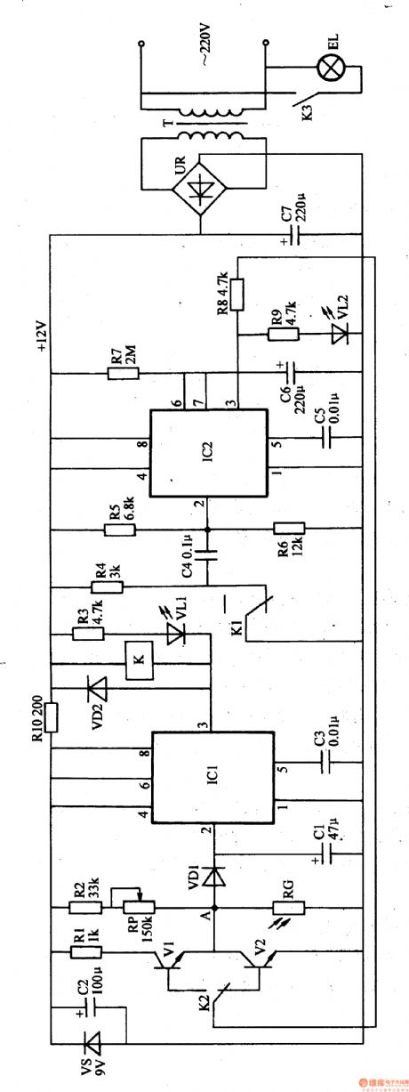
Light-Operated Streetlight (8)
Published:2011/7/6 0:56:00 Author:Sue | Keyword: Light-Operated, Streetlight

When S1 is connected, the 220v ac voltage will provide V1 with working voltage after it is reduced by T, rectificated by VD1, filtrated by C1, limited by R1, stablized by VS. The other circuit will charge C2 by S2,R2 and VD2, which will make V1 and V2 connected.Then V3's trigger voltage has a small phase angle. VT is connected in the ac electric's full period. EL will be illuminated.
When it is 23 o'clock, the electronic timer's normally closed contactor S2 is disconnected and C2 is disconnected. V1's base current can only be powered by C2's stored power. As C2 is discharged, V2's inner resistance value is becoming larger and V3's trigger phase angle is becoming larger. When C2 finishes discharging, V1 and V2 are disconnected. VT is connected by R6's and C3's shift voltage. When theshift angle reaches the largest value,EL is illuminated. (View)
View full Circuit Diagram | Comments | Reading(661)
Illumination Controller (23)
Published:2011/7/6 6:43:00 Author:Sue | Keyword: Illumination, Controller
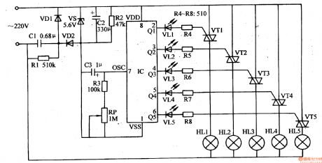
The 220v ac voltage will provide IC with 5.6v direct current working voltage after it is reduced by C1, rectificated by VD1 and VD2, stablized by VS, filtrated by C2.
After IC begins to work, its Q1-Q5 terminals will output control level in turn which will make VT1-VT5 connected in turn. Then the illuminations HL1-HLU are illuminated in turn which will realise running circular illumination effect.
IC's inner oscillator's oscillate frequency will be changed by adjusting RP's resistance value. Then the illumination effects can be changed. (View)
View full Circuit Diagram | Comments | Reading(658)
Illumination Controller (22)
Published:2011/7/6 6:27:00 Author:Sue | Keyword: Illumination, Controller
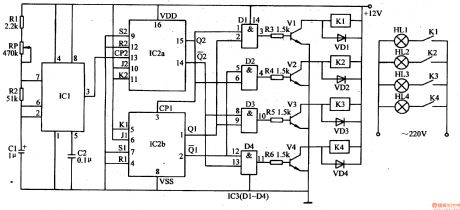
After the oscillator begins to work, IC1's pin 3 will output clock pulse signals. After the clock pulse signals are frequency divided by frequency divider, IC2's 4 terminals (pin 1, pin 2, pin 14, pin 15) will output control signals which will make AND GATE circuits D1-D4 output high level circularly.
When oneAND GATE circuit outputs high level, the tryristor which is conected to its output terminal will be connected. The relay is connected. Its normally open trigger will make the ac power connected. For example, when D1 outputs high level, V1 will be connected which will make K1 connected. The illuminations controlled by K1's normally open trigger will be illuminated. (View)
View full Circuit Diagram | Comments | Reading(684)
| Pages:211/312 At 20201202203204205206207208209210211212213214215216217218219220Under 20 |
Circuit Categories
power supply circuit
Amplifier Circuit
Basic Circuit
LED and Light Circuit
Sensor Circuit
Signal Processing
Electrical Equipment Circuit
Control Circuit
Remote Control Circuit
A/D-D/A Converter Circuit
Audio Circuit
Measuring and Test Circuit
Communication Circuit
Computer-Related Circuit
555 Circuit
Automotive Circuit
Repairing Circuit