
Index 213
Illumination Controller (25)
Published:2011/7/6 7:16:00 Author:Sue | Keyword: Illumination, Controller
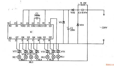
The 220v ac voltage will provide IC with 6v direct current working voltage after it is reduced by C3, rectificated by VD1,VD2, stablized by VS, filtrated by C2.
IC's Q1-Q7 terminals serve as drive signals output terminals. B1-B3 terminals serve as various choices control terminals. Uc and UD serve as consumption control terminals. OSC1 and OSC2 serve as oscillate terminal.
After IC begins to work, its Q1-Q7 terminals will output drive signals which will control the7 circuits of illuminations HL1-HL7 by VT1-VT7.
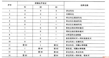
When IC's B1-B3 terminals are not connected, illuminations HL1-HL7's illumination effects are multipoint illumination, as seen in figure 1-3.When the illuminations are used, the illumination effects can be set according to actual requirement. (View)
View full Circuit Diagram | Comments | Reading(628)
Illumination Controller (24)
Published:2011/7/6 7:00:00 Author:Sue | Keyword: Illumination, Controller
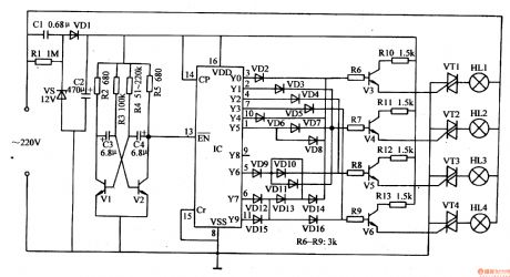
The 220v ac voltage will provide multivibrator, pulse frequency divider, drive control circuit with about 12v direct current voltage after it is reduced by C1, stablized by VS, rectificated by VD1, filtrated by C2.
After the multivibrator begins to work, it generates low frequency pulse signals which will serve as IC's pin 13's count pulse(use the count pulse's reduction trigger counter's method). Under the control of the count pulse, IC's Y0-Y9 terminals will output high level in turn, which will make drive control circuit begin to work through VD2-VD6. The illuminations HL1-HM will be illuminated. (View)
View full Circuit Diagram | Comments | Reading(631)
Metal Proximity Switch
Published:2011/7/7 2:34:00 Author:Felicity | Keyword: Metal Proximity Switch
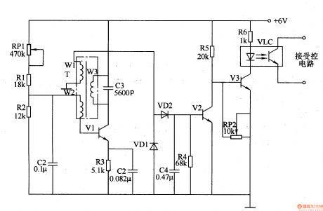
Work of the circuit The circuit consists of high-frequency oscillator circuit, voltage rectifier circuit, and electronic switching circuit. (It is showed in picture 8-131.)High-frequency oscillator circuit consists of high frequency transformer T, potentiometer RPl, resistors Rl-R3, capacitor Cl-C3 and transistor Vl.Voltage rectifier circuit consists of diode VDl and VD2, capacitor C4 and resistor R4.Electronic switching circuit consists of transistor V2 and V3, potentiometer Rm, optocouplers VLC and resistors R5, R6. (View)
View full Circuit Diagram | Comments | Reading(973)
Liquid Level Controller (the 6th)
Published:2011/7/7 21:20:00 Author:Felicity | Keyword: Liquid Level Controller
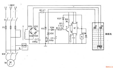
Work of the circuit
The circuit consists of power circuit, liquid level detection circuit and control implementation circuit. (It is showed in picture 8-104.)
Power circuit consists of Knife switch Q, fuse FU, power transformer T, rectifier diode VDl-VD4, current limiting resistor Rl and R5, filter capacitor Cl and voltage diode VS.
Liquid level detection circuit consists of high level electrode H, low level I electrode and the main electrode M.
Control implementation circuit consists of transistor V, Relay K, time-base integrated circuit IC, diode VD5-VD8 and external RC components. (View)
View full Circuit Diagram | Comments | Reading(3309)
Liquid Level Controller (the 5th)
Published:2011/7/7 21:18:00 Author:Felicity | Keyword: Liquid Level Controller
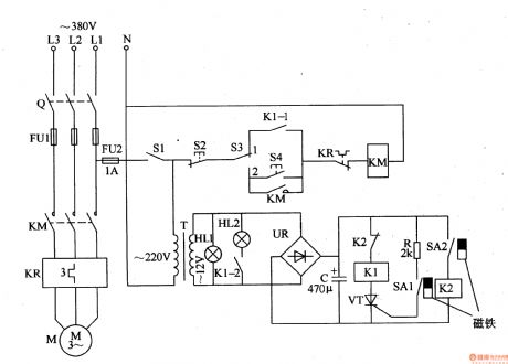
Work of the circuit
The circuit consists of power circuit and level detection and control circuit. (It is showed in picture 8-103.)
Power circuit consists of knife switch Q, fuse FUl, FU2, the power switch Sl, the power transformer T, to bridge rectifier UR and filter capacitor C.
Level detection and control circuit consists of reed SAl, SA2, relay Kl, Pakistan, Journal of crystal tube VT, resistor R, AC contactor KM, thermal relay KR, control button S2, sweet and manual / automatic control switch S3.
(View)
View full Circuit Diagram | Comments | Reading(989)
Liquid Level Controller (the 4th)
Published:2011/7/7 21:17:00 Author:Felicity | Keyword: Liquid Level Controller
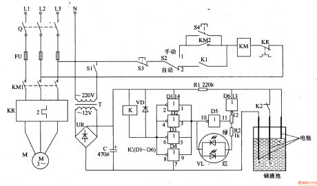
Work of the circuit
The circuit consists of power supply circuit, liquid level detection control circuit and indication starting control circuit. (It is showed in picture 8-102.)
Power supply circuit consists of Power transformer T, to bridge rectifier and filter capacitor C.
Liquid level detection control circuit consists of Liquid level detection electrode a-c, six non-gate IC IC (D1-D6), resistors Rl, R2, relay K, color light-emitting diodes VL and diode VD.
Indication starting control circuit consists of switch Q, fuse FUl-FU3, power switch Sl, manual / automatic control switch S2, the stop button S3, called the start button, AC contactors KM and thermal relays KR. (View)
View full Circuit Diagram | Comments | Reading(899)
Timing Controller (the 1st)
Published:2011/7/7 22:29:00 Author:Felicity | Keyword: Timing Controller
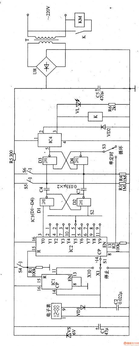
Work of the circuit
The circuit consists of Power supply circuit, the clock signal generator, counting distributor circuit, flip-flop circuit and control output circuit. (It is showed in picture 8-90.)
Power supply circuit consists of Power transformer T, bridge rectifier, UR, filter capacitor Cl, C5, current limiting resistor R5 and Zener VS.
The clock signal generator consists of electronic clock, diodes VDl, capacitor C2 and the count divider integrated circuit ICl.
Counting distributor circuit consists of count divider integrated circuit IC2, resistors Rl, R2, timer selection switch Sl, S2 and reset button S4.
Flip-flop circuit consists of NAND gate integrated circuit IC3 (Dl-D4) and capacitor C3, C4, resistor R3, R4, the Close button S5, S6 on the button and loop / single timer switch S3.
Control output circuit consists of electronic switch integrated circuit IC4, diode VD2, relay K, light-emitting diode VL, resistors R6 and AC contactor KM. (View)
View full Circuit Diagram | Comments | Reading(751)
The ultraviolet fire sound/light alarm equipment circuit
Published:2011/7/8 2:27:00 Author:Seven | Keyword: ultraviolet, alarm equipment
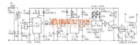
See as the figure, the circuit consists of the ultraviolet sensor Buv, the single stable trigger circuit, anti-false alarm judging circuit, fire fighting truck sound making alarm circuit and AC step-down rectifier circuit, etc. (View)
View full Circuit Diagram | Comments | Reading(744)
Using IRFP250 power tube H-bridge motor drive circuit
Published:2011/7/8 2:42:00 Author:Fiona | Keyword: power tube, H-bridge motor drive
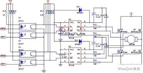
The drive circuit of electromotor includes a FET bridge circuit, FET base drive circuit,current sensor of motor drive circuit and the relay. FET bridge circuit mainly consists of four high-power MOSFET power tubes,it requires that the power tubes have good switching characteristics,can withstand higher drive current and have a long life.According to motor power parameters and power tube limit parameters and the electrical characteristics,we use four the same N-channel IRFP250power tubes to form the H-bridge circuit.
(View)
View full Circuit Diagram | Comments | Reading(6984)
Saving lighting control circuit
Published:2011/7/8 1:33:00 Author:Fiona | Keyword: Saving lighting
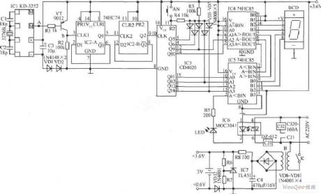
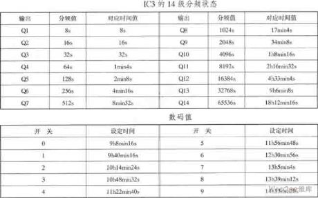
At time t1,the M of IC1 is in a high impedance state, VT cuts off; at the time t2, the M of IC1 outputs the negative pulse, VT conducts and outputs qualified clock signal CLK1 from VT collector. IC2 is a dual D flip-flop,it feedbacks the reversed output terminalto the data input terminal D to connect 2 divider, the data output terminal Q1 of IC2-A and clock input terminal CLK2 of IC2-B are connected to make up a 4 divider, the 4-frequency signal inputs into IC3 to do 14 divide, so that the second signal does 18 divide, the 14 divide state of the IC3 is shown in table.
(View)
View full Circuit Diagram | Comments | Reading(721)
Liquid Level Controller (the 3rd)
Published:2011/7/7 21:16:00 Author:Felicity | Keyword: Liquid Level Controller
Work of the circuit
The circuit consists of power circuit, liquid level detection circuit and control implementation circuit. (It is showed in picture 8-101.)
Power circuit consists of power transformer T, rectifier diode VDl-VD4 and filter capacitor C.
Liquid level detection circuit consists of high-level electrode A, low-level electrode B and the main electrode C.
Control implementation circuit consists of relay K, the control transistor V and AC contactor KM. (View)
View full Circuit Diagram | Comments | Reading(2101)
Liquid Level Controller (the 1st)
Published:2011/7/7 21:06:00 Author:Felicity | Keyword: Liquid Level Controller
Work of the circuit
The circuit consists of power circuit and level detection and control circuit. (It is showed in picture 8-99.)
Level detection and control circuit consists of detection electrodes,-c, control buttons S2, S3, resistors Rl-R4, transistor Vl, V2, light-emitting diode VLl, VL2, relay K, AC contactor KM and diode VD.
(View)
View full Circuit Diagram | Comments | Reading(976)
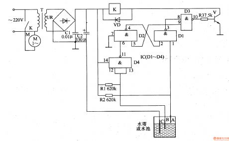
Engine Water Supply Alarm Four
Published:2011/7/7 7:34:00 Author:Felicity | Keyword: Engine Water Supply Alarm
When the water level of the tank is above the lowest water level, electrode is connected to ground (the iron) through the resistance of water. And the input voltage of D1 is low; the output voltage of D2 is low and the output voltage of D3 is high. The green LED inside VL is on. And the output voltage of D4 is low; VD is on; the audio oscillator consists of D5, D6, R3 and C2 doesn’t work, HA is noiseless.When the water level is the same as the lowest water level (i.e. the electrode is just above the water), the output of D3 is at high level and the green LED inside VL is on while the green on is off. And the output of D4 is at high level to make VD cut off and then the audio oscillator works, then HA send out beeps.
(View)
View full Circuit Diagram | Comments | Reading(783)
The warm-up time and the charge(2LT type, 2L diesel engine) theory circuit of 70 light sport utility vehicle of Toyota Land Cruiser
Published:2011/6/26 4:31:00 Author:Sophia | Keyword: Warm-up time, Charge(2LT type, 2L diesel engine), theory circuit, 70 light sport utility vehicle of Toyota Land Cruiser
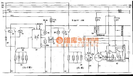
Off-road vehicles with a 2L-T type or 2L diesel engine, in general,fit the electric plug inside the cylinder. the glow plugs 35 is controlled by the relay 33, relay coil 33 is controlled by the warm-up timer 37. Warm-up timer work when plug 38a installed in the cooling system inputs the water temperature. When the water temperature is above 5 ℃, if the ignition switch is switched on, preeat indicator light will flash about 38 (about 0.3S), which means that can be started directly; if the water temperature is below 5 ℃, the preheat light 38 will stay on for an period of time (about 18S), until the temperature of warm-up plugs inside the cylinder reaches 800 ℃ or so and lights is off, which shows the vehicle can be started. 70 light-duty off-road vehicle also is equipped with emission control systems. When the water temperature is low, the fuel will have poor atomization, incomplete combustion production is excessive. Emission controller 46 will control the throttle idle switch electromagnetism valve 44, while make the cold mixture heater work and heat up atomization. (View)
View full Circuit Diagram | Comments | Reading(2549)
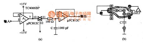
In-phase sample-and-hold circuit
Published:2011/6/19 23:32:00 Author:Sophia | Keyword: In-phase, sample-and-hold circuit
(View)
View full Circuit Diagram | Comments | Reading(673)
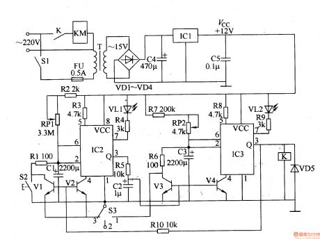
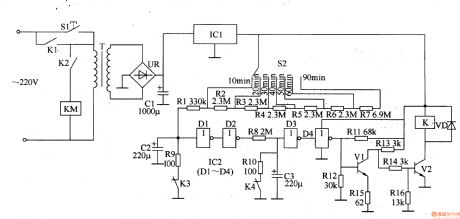
Timing Controller (the 6th)
Published:2011/7/7 22:34:00 Author:Felicity | Keyword: Timing Controller (the 6th)
Work of the circuit
The circuit consists of power circuit, timing control circuit and control implementation circuit. (It is showed in picture 8-95.)
Power circuit consists of power switch Sl, fuse FU, power transformer T, rectifier diode VDl-VD4, filter capacitor C4, C5, and three-terminal regulator IC lCl.
Timing control circuit consists of time-base integrated circuit IC2, 1C3, resistors Rl-RlO, capacitors Cl-C3, potentiometer RPl, RP2, transistor Vl-V4, LED VL1, VL2, manual discharge button function selector switch S2 and S3.
Control implementation circuit consists of diode VD5, relay K and AC contactor KM. (View)
View full Circuit Diagram | Comments | Reading(724)
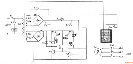
Engine Water Supply Alarm Two
Published:2011/7/7 3:21:00 Author:Felicity | Keyword: Engine Water Supply Alarm
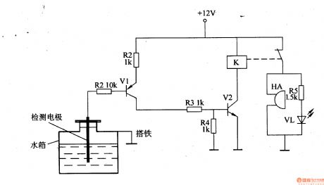
While the water level of the tank is higher than the lowest water level, the water level detect electrode is connected to ground through the resistance of water. V1 is on because of low level voltage of the base, and the high level voltage output by collector is divide by R3 ,R4 and then connect to the base of V2 to make V2 saturated and on and then K is on and the normally off contact of K is off ,then HA is noiseless and VL is off.While the water level in the tank is lower than the lowest water level , the water level detect electrode is above water to make V1 and V2 cut off, and K releases, HA is on and send out alarm, HL is on to warn the driver that the water level of tank is too low and should refill it
(View)
View full Circuit Diagram | Comments | Reading(1760)
Timing Controller (the 5th)
Published:2011/7/7 22:33:00 Author:Felicity | Keyword: Timing Controller
Work of the circuit
The circuit consists of power regulator circuit, timing time circuit, delay circuit and Schmitt trigger control circuit. (It is showed in picture 8-94.)
Power regulator circuit consists of start button SI, power transformer T, bridge rectifier, UR, filter capacitors Cl and three-terminal voltage regulator integrated circuit ICl.
Timing time circuit consists of selector switch S2 and resistors Rl-R7.
Delay circuit consists of capacitors C2, C3, resistors R9, RlO, the normally closed contact relay K K3, K4 and non-gate integrated circuits IC2 (D1-D4).
Schmitt trigger control circuit consists of transistor Vl, V2, resistors RI-R16 and diode VD. (View)
View full Circuit Diagram | Comments | Reading(677)
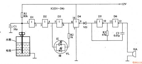
Engine Water Supply Alarm One
Published:2011/7/7 3:07:00 Author:Felicity | Keyword: Engine Water Supply Alarm
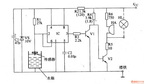
While the engine is not short of water, the electrode of the sensor is connected to ground (the iron) to make the voltage of pin 2 and pin 6 at low level (lower than Vcc/3). The output of pin 3 is at high level to make V1 on, and V2 cut off, then HA is noiseless and HL is off. While the water level of the engine is below the electrode of the sensor, the voltage of pin 2 and pin 6 are at high level (higher than 2Vcc/3). The circuit of IC changes and pin 3 outputs low voltage to make V1 cut off ,and V2 on, and then HA send out beeps and HL is also on to warn the driver the engine is short of water.
(View)
View full Circuit Diagram | Comments | Reading(913)
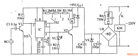
Timing Controller (the 4th)
Published:2011/7/7 22:31:00 Author:Felicity | Keyword: Timing Controller
Work of the circuit
The circuit consists of power circuit, the input control circuit, timing circuit and output control circuit. (It is showed in picture 8-93.)
Power circuit consists of Buck capacitor C6, discharge resistors R6, bridge rectifier, UR, filtering capacitor C5, C4 and Zener VS.
The input control circuit consists of the piezoelectric ceramic BC on Electronic alarm clock, capacitor Cl, resistors Rl and transistor Vl.
Timing circuit consists of Resistors Rl-R5, reset button, Sl, regular timing switch S2, capacitor C2 and C3, light-emitting diode VL and time -based integrated circuit IC.
Output control circuit consists of transistor V2, the relay K, the diode VD and AC contactor KM. (View)
View full Circuit Diagram | Comments | Reading(694)
| Pages:213/312 At 20201202203204205206207208209210211212213214215216217218219220Under 20 |
Circuit Categories
power supply circuit
Amplifier Circuit
Basic Circuit
LED and Light Circuit
Sensor Circuit
Signal Processing
Electrical Equipment Circuit
Control Circuit
Remote Control Circuit
A/D-D/A Converter Circuit
Audio Circuit
Measuring and Test Circuit
Communication Circuit
Computer-Related Circuit
555 Circuit
Automotive Circuit
Repairing Circuit