
Index 200
wireless remote control dimmable lamp(2)
Published:2011/7/17 20:50:00 Author:chopper | Keyword: dimmable lamp, remote control
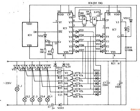
This example describes the wireless remote control dimmable droplight,which can control the working state of droplightat will.It not only cancontrol a certain lamp (or all lamps) to turn on or turn off, but also can make the various incandescent lamps in the droplight lighted in order circularly to produce the effect like water light . The principle of circuitThe wireless remote control dimmable droplight circuit is formed by the wireless remote control transmitter circuit and wireless remote control receiver circuit. Wireless remote control transmitter circuit is formed by the pulse encoder circuit and wireless transmitter circuit,which is shown in Figure 1-199
(View)
View full Circuit Diagram | Comments | Reading(608)
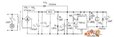
eyes care lamp(3)
Published:2011/7/17 20:36:00 Author:chopper | Keyword: care lamp
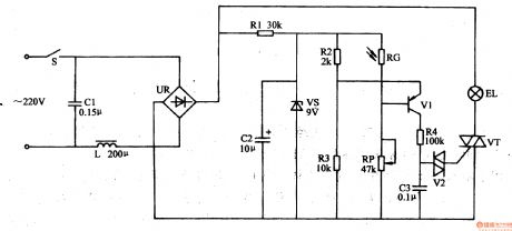
This example describes the eyes care lamp,which can dim the light level based on the intensity of indoor light level automatically. And it can protect the eyes and it is suitable for reading and writing. The principle of circuitThe eyes care lamp circuit is formed by the power circuit and optical control circuit,which is shown in Figure 1-192. Power supply circuit is formed by the power switch S, filter capacitors C1,C2,inductor L,bridge rectifier UR, current limiting resistor R1 and diode voltage regulator VS. The optical control circuit is formed by the photosensitive resistor RC, resistors R2-R4, potentiometer RP, capacitor C3, transistor V1,and dual-track trigger diode V2 and thyristor VT.
(View)
View full Circuit Diagram | Comments | Reading(648)
Video switch using MC1545 circuit
Published:2011/7/12 10:02:00 Author:John | Keyword: Video switch

Video switch using MC1545 circuit is as shown. MC1545 is the gated broadband amplifier, which is used as a video switch. The input is with differential mode. The door switch is used to convert two amplifiers A and B. A is selected to high electricity level and B is for low one. The output is also with differential output terminals. Gate input signal refers to TTL level, whose gated conversion time can be 20ns. When the gate signal is at high level, the video input signal is taken as an output signal. When the gate signal is at low level, the amplifier A is at the off state.
(View)
View full Circuit Diagram | Comments | Reading(632)
Video switch circuit
Published:2011/7/12 10:06:00 Author:John | Keyword: Video switch
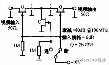
Video switch circuit is as shown. 2N4391 FET provides the circuit with only 30Ω induction -resistance and less than 0.2pF pinch-off is capacitance. This performance can be comparable with that of the ideal high-frequency switch. The attenuation for 100MHz circuit is more than 80dB and the insertion loss is about 6dB.
(View)
View full Circuit Diagram | Comments | Reading(750)
DPDT FET switch circuit
Published:2011/7/12 10:13:00 Author:John | Keyword: DPDT FET switch, FET
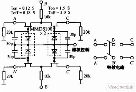
DPDT FET switch circuit is as shown. When the FET is inducted, the resistance of the drain channel can be up to thousands of MΩ. Therefore, FET can constitute an ideal low-frequency switch. Capacitance of ends of the FET is not good to do isolation for high-frequency signals. Thus, response time can be increased and maximum operating frequency can be limited.
(View)
View full Circuit Diagram | Comments | Reading(1296)
Two-phase servo drive circuit
Published:2011/7/12 10:22:00 Author:John | Keyword: Two-phase servo drive
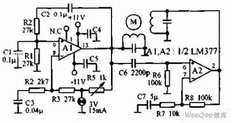
Two-phase servo drive circuit is as shown, which utilizes two components of an integrated power amplifier LM377. These two components, respectively, produce power of 3W to drive small 60Hz two-phase servo motor. The motor winding is of 8Ω, which is tuned to 60Hz with the shunt capacitor. The light bulb is used in steady ring circuit.
(View)
View full Circuit Diagram | Comments | Reading(700)
crops automatic frost prevention controller(2)
Published:2011/7/15 20:55:00 Author:chopper | Keyword: frost prevention
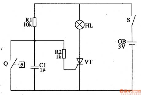
The principle of circuitThe crops automatic frost prevention controller circuit is formed by electric contact mercury thermometer Q,the control circuit and ignition device and other components, which is shown in figure 4-108.
What's the difference between the electric contact mercury thermometer and normal mercury thermometers is that in this mercury thermometer there are two platinum electrodes,and one is inserted in the contact electrode of the upper mercury warehouse,the other is inserted in the control electrode of temperature scale which is required control. It should set the measurement temperature (smoke combustion temperature) at +1 ℃ when it is in usage. (View)
View full Circuit Diagram | Comments | Reading(624)
Five control lamp switch circuit
Published:2011/7/5 21:29:00 Author:zj | Keyword: Five control, lamp switch circuit
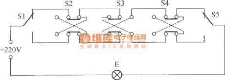
As the Figure shows, it isa five control switch circuit. S1 ~ S5 are respectively arranged in 5 different places, but they can independently control lamp E lit or extinguished. Among them: S1, S5 1 x 2 single-pole double-throw switch, S2 ~ S4 with 2 x 2 double pole double throw switch. (View)
View full Circuit Diagram | Comments | Reading(616)
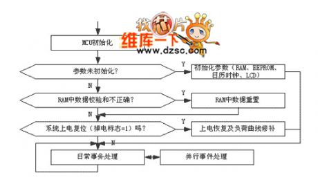
Daily Work Transaction Processing Flow Diagram Circuit
Published:2011/7/16 21:30:00 Author:Robert | Keyword: Daily Work, Transaction, Processing, Flow Diagram
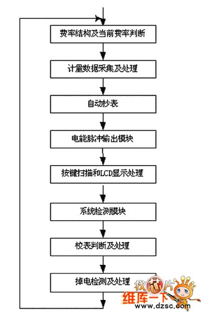
The picture shows the daily work transaction processing flow diagram circuit. (View)
View full Circuit Diagram | Comments | Reading(712)
Clock Circuit Main Program Flow Diagram Circuit
Published:2011/7/16 21:22:00 Author:Robert | Keyword: Clock, Program, Flow Diagram
The picture shows the clock circuit main program flow diagram circuit. (View)
View full Circuit Diagram | Comments | Reading(694)
Ringing switch power supply over-current protection circuit
Published:2011/7/15 22:32:00 Author:Christina | Keyword: Ringing switch, power supply, over-current, protection circuit
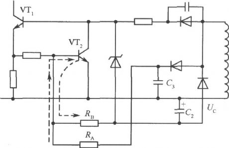
In the ringing current-limit switching power supply, the output current Io has no corresponding relationship with the primary stage current Ic. For the same collector electrode current Ic, with the rise of the input voltage, the Io will increase too. So in the ringing type switching circuit, in addition to use the start protection measures, we also need to set the protection circuit which is as shown in the figure. We add the RA and RB on the base subcircuit of VT2. Because the voltage of C3 is the positive polarity voltage which is proportional to the input voltage, so if the input voltage Vi rises, the current which flows through the resistance RA will increase to accelerate the conduction of VT2.
(View)
View full Circuit Diagram | Comments | Reading(645)
Brushless DC Motor Driving Circuit
Published:2011/7/17 7:12:00 Author:Robert | Keyword: Brushless, DC, Motor, Driving
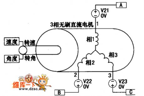
The brushless DC motor driving circuit is shown in the picture. (View)
View full Circuit Diagram | Comments | Reading(1180)
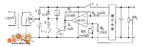
Over-Voltage Adjustable Protection Circuit
Published:2011/7/16 9:41:00 Author:Robert | Keyword: Over-Voltage, Adjustable, Protection

The picture shows the over-voltage adjustable circuit. (View)
View full Circuit Diagram | Comments | Reading(608)
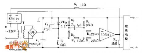
Simple And Reliable Commercial Power Over-Voltage Protector Circuit
Published:2011/7/17 8:07:00 Author:Robert | Keyword: Simple, Reliable, Commercial Power, Over-Voltage, Protector
The picture shows the simple and reliable commercial power over-voltage protector circuit. (View)
View full Circuit Diagram | Comments | Reading(668)
Stabilized Voltage Supply Adding Additional Over-Voltage Protection Circuit
Published:2011/7/17 8:10:00 Author:Robert | Keyword: Stabilized Voltage Supply, Over-Voltage, Protection
The picture shows the stabilized voltage supply adding additional over-voltage protection circuit. (View)
View full Circuit Diagram | Comments | Reading(545)
Over-Voltage Protection Circuit By Using The Principle Of Over-Heat Generated By Over-Voltage
Published:2011/7/17 8:04:00 Author:Robert | Keyword: Over-Voltage, Protection, Principle, Over-Heat
The pictrue shows the over-voltage protection circuit by using the principle of over-heat generated by over-voltage. (View)
View full Circuit Diagram | Comments | Reading(604)
Over-Voltage Protection Circuit Composed Of Fuse And Thyristor
Published:2011/7/17 9:42:00 Author:Robert | Keyword: Over-Voltage, Protection, Fuse, Thyristor
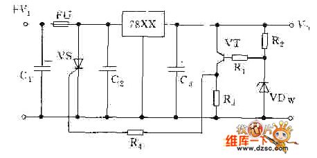
The picture shows the over-voltage protection circuit composed of fuse and thyristor. (View)
View full Circuit Diagram | Comments | Reading(787)
Over-Voltage Protection Circuit Composed Of Transistors
Published:2011/7/16 9:47:00 Author:Robert | Keyword: Over-Voltage, Protection, Transistor
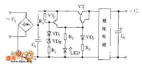
The picture shows the over-voltage protection circuit composed of transistors. (View)
View full Circuit Diagram | Comments | Reading(664)
Over-Voltage Protection Circuit Composed Of Transistor And Relay (2)
Published:2011/7/16 9:55:00 Author:Robert | Keyword: Over-Voltage, Protection, Transistor, Relay

The picture shows the over-voltage protection circuit composed of transistor and relay (2). (View)
View full Circuit Diagram | Comments | Reading(640)
Over-Voltage Protection Circuit Composed Of Transistor And Relay (1)
Published:2011/7/16 9:52:00 Author:Robert | Keyword: Over-Voltage, Protection, Transistor, Relay
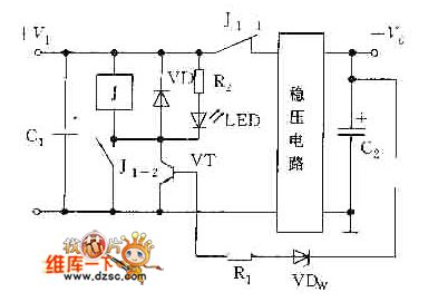
The picture shows the over-voltage protection circuit composed of transistor and relay (1). (View)
View full Circuit Diagram | Comments | Reading(665)
| Pages:200/312 At 20181182183184185186187188189190191192193194195196197198199200Under 20 |
Circuit Categories
power supply circuit
Amplifier Circuit
Basic Circuit
LED and Light Circuit
Sensor Circuit
Signal Processing
Electrical Equipment Circuit
Control Circuit
Remote Control Circuit
A/D-D/A Converter Circuit
Audio Circuit
Measuring and Test Circuit
Communication Circuit
Computer-Related Circuit
555 Circuit
Automotive Circuit
Repairing Circuit