
Index 196
74 series digital circuit 74184 binary system BCD converter
Published:2011/7/19 1:44:00 Author:TaoXi | Keyword: 74 series, digital circuit, binary system, BCD, converter
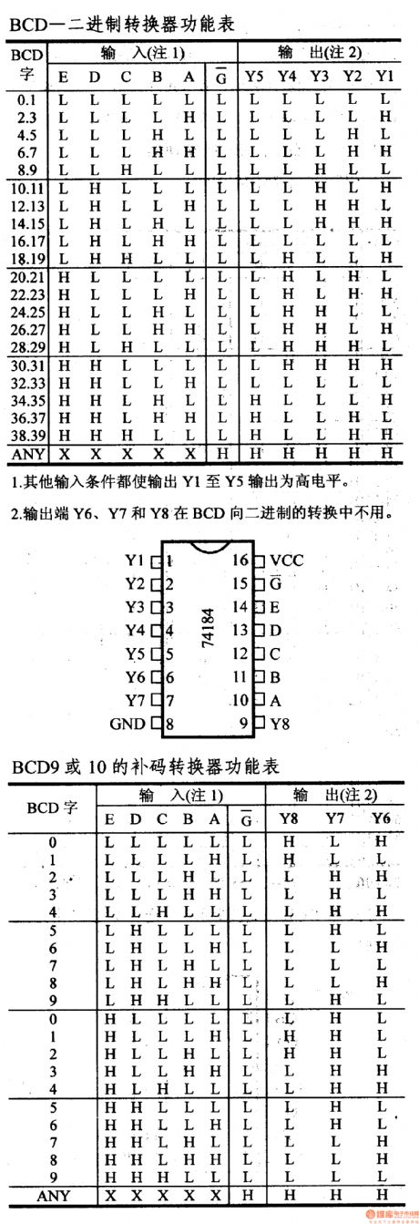
1.The other input conditions make the Y6, Y7 and Y8 output the high level.2.The outputs Y1-Y5 will not be used in the BCD9 or BCD10's complement conversion.3.When it is used as the complement inverter, the input E is used as the mode control, when this port's output is low, it produces the complement number of BCD9, when this port's output is high, it produces the complement number of BCD10.
(View)
View full Circuit Diagram | Comments | Reading(1992)
74 series digital circuit 74H183, 74LS183 dual carry save adder
Published:2011/7/19 1:36:00 Author:TaoXi | Keyword: 74 series, digital circuit, dual carry, save adder
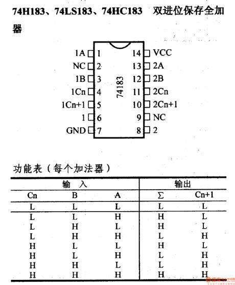
74 series digital circuit 74H183, 74LS183 dual carry save adder
(View)
View full Circuit Diagram | Comments | Reading(2654)
CH217 (alarm device) single chip gas detection alarm circuit
Published:2011/7/20 21:07:00 Author:TaoXi | Keyword: alarm device, single chip, gas detection, alarm circuit
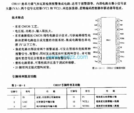
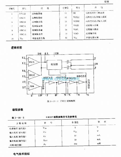
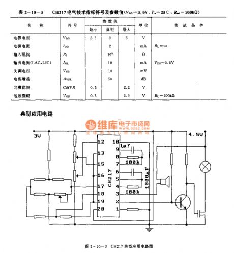
The CH217 is designed as the single chip gas detection alarm circuit that can be used in the alarm device. The internal circuit is composed of the small signal amplifier (VA),two signal comparators (VC1 and VC2), two groups of oscillator, logic code controller and the driver.
Features
The CMOS technology.Low voltage, small power consumption, large input impedance.It uses the new low-voltage CMOS linear circuit design technology, the linear circuit and logic circuit will be combined into the complete function system.The IC can operate in single power 3V condition.The integrated circuit has two internal alarm channels.20-pin dual-row DIP plastic package.
(View)
View full Circuit Diagram | Comments | Reading(770)
United reaper full warehouse reminder (1)
Published:2011/7/19 23:16:00 Author:chopper | Keyword: United reaper, full warehouse reminder
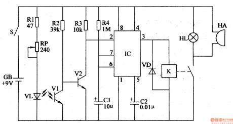
The principle of circuitThe united reaper full warehouse reminder circuit is formed by the photoelectric detection amplification circuit,monostability circuit and the sound and light alarm circuit,which is shown in Figure 4-98. The photoelectric detection amplification circuit is formed by the infrared light-emitting one-diode VL,resistors R1-R3, potentiometer RP, infrared phototransistor V1 and transistor V2. The monostability circuit is formed by the time-base integrated circuit IC,resistor R4 and capacitors C1, C2. The sound and light alarm circuit is formed by the relay K, one-diode VD, indicator light HL and buzzer HA.
(View)
View full Circuit Diagram | Comments | Reading(549)
United reaper full warehouse reminder (2)
Published:2011/7/19 23:16:00 Author:chopper | Keyword: United reaper, full warehouse reminder
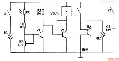
The principle of circuitThis united reaper full warehouse reminder circuit is formed by the photoelectric detection amplification circuit and the sound and light alarm circuit,which is shown in Figure 4-99.The photoelectric detection amplification circuit is formed by the indicator light HL1,light switche S1,photosensitive resistor and transistor V1. The sound and light alarm circuit consists of transistor V2, the relay K, the diode VD, indicator light HL2 and buzzer HA.
(View)
View full Circuit Diagram | Comments | Reading(681)
seeder spray pipe water break alarm (1)
Published:2011/7/19 23:44:00 Author:chopper | Keyword: seeder, spray pipe, water break, alarm
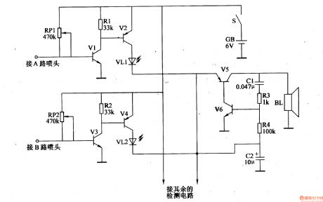
This example describes the seeder spray pipe water break alarm, which can send a sound and light alarm in time to remind workers to process timely when the water breaks. The principle of circuitThe seeder spray pipe water break alarm circuit is formed by water break detection circuit and the sound and light alarm circuit,which is shown in Figure 4-102. Water break detection circuit is formed by the transistors V1,V3,potentiometers RP1,RP2,and resistors R1,R2,etc. Sound and light alarm circuit is formed by the transistors V2,V4-V6,light-emitting diodes VL1,VL2, resistors R3,R4,capacitor C1,C2 and the speaker BL. V2,V4 and VL1,VL2 form the LED indication circuit,and V5,V6 and C1,C2,R3,R4 form the audio oscillator circuit.
(View)
View full Circuit Diagram | Comments | Reading(570)
wireless remote control dimmable lamp(1)
Published:2011/7/19 23:43:00 Author:chopper | Keyword: wireless, remote control, dimmable lamp
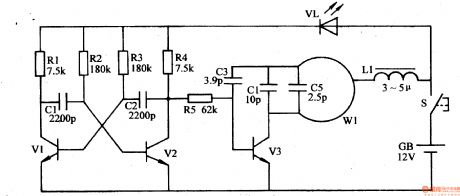
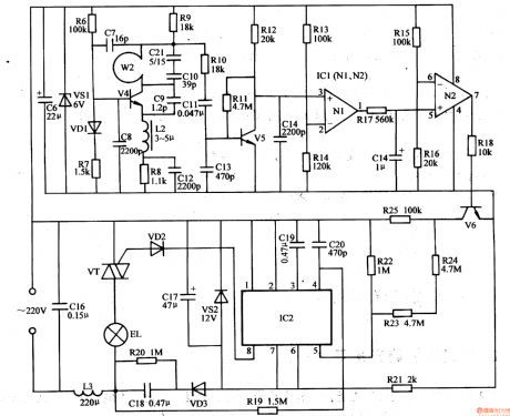
Decorative lights like general droplights are not of remote control and dimming functions,and they are very uneasy to use. This example describes the wireless remote control dimmable droplight, which is with power on/off and multi-level dimming functions,and the control distance is about 20m. The principle of circuitThe wireless remote control dimmable droplight circuit is formed by the wireless remote control transmitter circuit and wireless receiver dimmable controller circuit. Wireless remote control transmitter circuit is formed by the astable multivibrator,high-frequency oscillator,which is shown in Figure 1-197
(View)
View full Circuit Diagram | Comments | Reading(1308)
seeder spray pipe water break alarm (2)
Published:2011/7/19 23:25:00 Author:chopper | Keyword: seeder, spray pipe, water break alarm
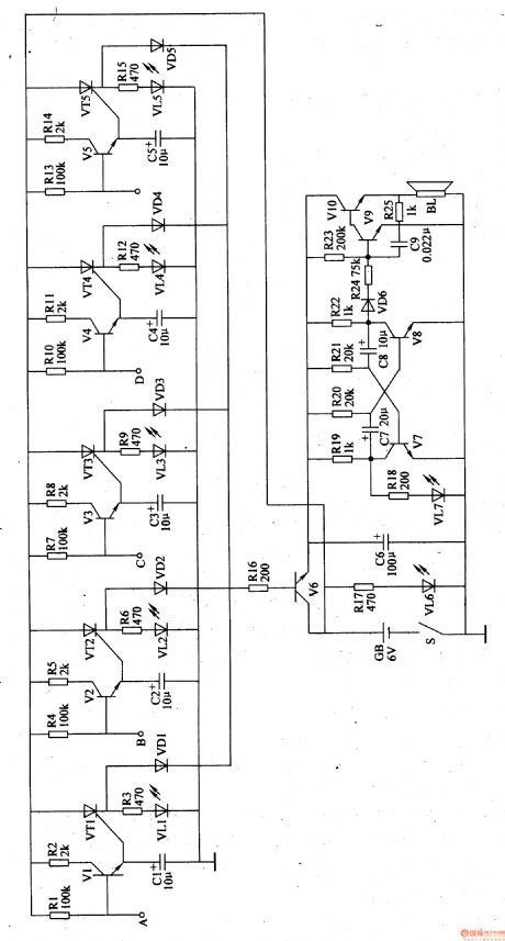
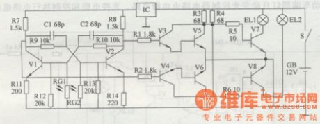
The principle of circuitThe seeder spray pipe water break alarm circuit is formed by water break detection circuit and the sound and light alarm circuit,which is shown in Figure 4-103. The water break detection circuit is formed by the transistors V1-V5,resistors R1,R2,R4,R5,R7,R8,R10,R11,R13,R14 and capacitors C1-C5. The sound and light alarm circuit is formed by the transistors V6-V10,thyristors VT1-VT5,LEDs VL1-VL5,resistors R3,R6,R9,R12,R16,R18-R25,capacitors C7-C9 and speaker BL. The VT1-VT5 and VL1-VL5 and R3,R6,R9,R12 form the LED indication circuit; and VD1-VD5,R16,V6 and C6 form the control circuit.V7,V8,and R18-R22, C7,C8,VL6,VL7 form multivibrator circuit; V9,V10 and C9,R23-R25 form the controlled audio oscillator circuit. The sides A-E are connected to 5 water pipes respectively. R17 is a current limiting resistor, VL6 is the power indicator.
(View)
View full Circuit Diagram | Comments | Reading(529)
seeder spray pipe water break alarm (4)
Published:2011/7/19 23:43:00 Author:chopper | Keyword: seeder, spray pipe, water break alarm
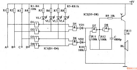
The principle of circuit The seeder spray pipe water break alarm circuit is formed by the water break detection circuit,LED indication circuit,trigger control circuit and the alarm circuit,which is shown in figure 4-105. The water break detection circuit consists of non-gate integrated circuit IC1(D1-D4)and resistors R1-R4. The ends A-D are respectively connected with four water pipes.LED indication circuit consists of resistors R5-R8 and LED VL1-VL4. Trigger control circuit consists of the non-gate D5,D6 in the non-gate integrated circuit IC2 (D5-D8) and diodes VD1,VD2,resistor R10. (View)
View full Circuit Diagram | Comments | Reading(586)
agricultural non-tower pressure-charged water feeder(2)
Published:2011/7/19 23:41:00 Author:chopper | Keyword: agricultural, non-tower, pressure-charged, water feeder
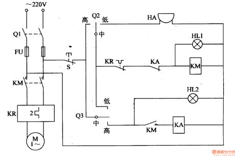
This example describes the agricultural non-tower pressure-charged water feeder,and it uses electric connecting pressure gauge as the measurement and control device.The circuit is simple, and it can cut off the power supply automatically when the water supply is not enough or the submersible pump fails to work,while the alarm sends a sound. The principle of circuit This agricultural non-tower pressure-charged water feeder circuit is formed by the knife switch Q1,fuse FU,intermediate relay KA,AC contactor KM, thermal relay KR,alarm HA, lights HL1,HL2 and the control contact of pump outlet pressure gauge Q2,control contact of tank water level testing gauge Q3, which is shown in figure 4-153.
(View)
View full Circuit Diagram | Comments | Reading(595)
greenhouse ground hotline controller(1)
Published:2011/7/19 23:40:00 Author:chopper | Keyword: greenhouse, ground hotline, controller
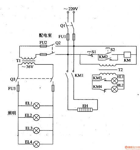
In the northern winter and spring, farmers usually lays the ground hotline to assist warming in order to increase the temperature inside the greenhouse,and promote the growth of seedlings,vegetables.Here is a ground hotline controller of common-used single-phase power for installation reference. The principle of circuitThis greenhouse ground hotline controller circuit is formed by the control circuit,working status indication circuit and low voltage lighting circuit, which is shown in figure 4-198.
(View)
View full Circuit Diagram | Comments | Reading(592)
greenhouse ground hotline controller(2)
Published:2011/7/19 23:38:00 Author:chopper | Keyword: greenhouse, ground hotline, controller
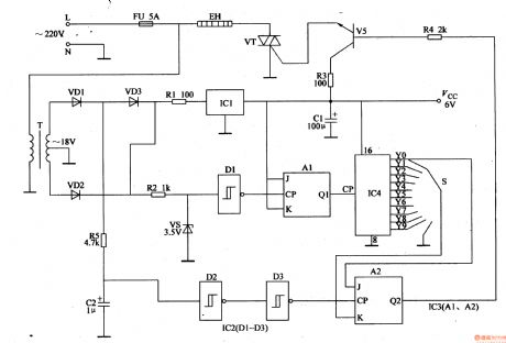
This example describes the greenhouse ground hotline controller, which uses the cycle rate control,and it is of advantages like energy saving, small harmonic interference and so on. The principle of circuitThe greenhouse ground hotline controller circuit is formed by power supply circuit and heating control circuit, which is shown in figure 4-199. Power supply circuit is formed by the fuse FU,power transformer T,rectifier diodes VD1-VD3, resistor R1,three-terminal voltage regulator integrated circuit IC1 and filter capacitor C1. Heating control circuit consists of resistors R2-R5,capacitor C2,voltage regulator diode VS,non-gate Schmitt trigger integrated circuit IC2 (D1-D3), trigger JK integrated circuit IC3 (A1,A2,counting/pulse distribution integrated circuit IC4, selective switch S,the transistor V,thyristor VT and ground hotline EH.
(View)
View full Circuit Diagram | Comments | Reading(1010)
motor headlight auto-changing controller(II)
Published:2011/7/19 23:36:00 Author:chopper | Keyword: motor, headlight, auto-changing controller
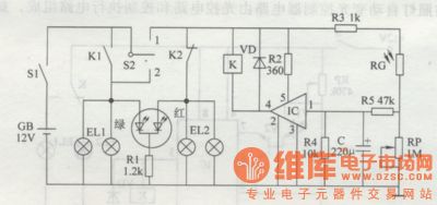
Principle of the circuit The motor headlight auto-changing controller circuit is formed by the optical detection circuit,control implementation circuit and LED indication which is shown in figure 7-2. Photoelectric detection circuit is formed by the photosensitive resistor RG,resistors R3-R5,capacitor C and the potentiometer RP. Control implementation ircuit is formed by the electronic switching integrated circuit IC,resistor R2,diode VD and relay K. LED indication circuit is formed by resistors Rl and color-changing light-emitting diode VL. S1 is the switch of vehicle key, S2 is the vehicle switch of turn light.
(View)
View full Circuit Diagram | Comments | Reading(602)
headlamp delay shutoff device
Published:2011/7/14 20:44:00 Author:chopper | Keyword: headlamp, delay shutoff
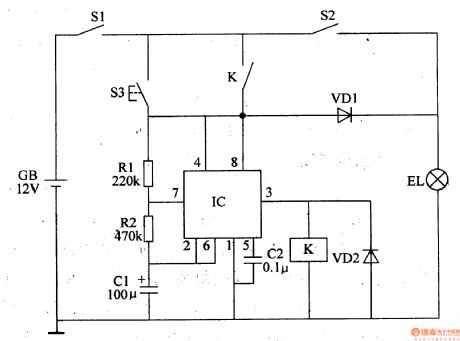
This example describes the headlamp delay shutoff device, and the headlamps can continue lighting a period of time before they close automatically when drivers press the delay button,thus it can offer a short time emergency lighting when the drivers park and leave in the night. The principle of circuit The headlamp delay shutoff device circuit includes the delay button S3,resistors R1,R2,capacitor C1,C2,diode VD1,VD2, relay K and time-base integrated circuit IC,which is shown in figure 7-32 . EL is the motor headlamp,S1 is the total power switch for the automotive,and S2 is the headlamp switch.
(View)
View full Circuit Diagram | Comments | Reading(708)
motor headlamp auto-changing controller(3)
Published:2011/7/19 23:36:00 Author:chopper | Keyword: motor, headlamp, auto-changing controller
According to traffic safety rules,it should open high beam (bright light) when motors drive at night,but it should open low beam(weak light) when motors meet.Thus,drivers sholuld control the operation light by hands or feet several times when it meets at every time.This example describes motor headlamp auto-changing controller produced by discrete components,and it can automatically transform the high beam and low beam of motor when the motors meet to decrease the intensity of labour of drivers,and ensure safety. The principle of circuit The controller circuit consists of bistable trigger circuit and switching control circuit,which is shown in figure 7-3.
(View)
View full Circuit Diagram | Comments | Reading(710)
Generic Subtractor Circuit
Published:2011/7/14 8:36:00 Author:Joyce | Keyword: Generic , Subtractor
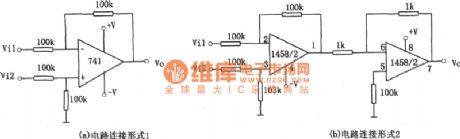
The relation of input and output of the circuit in figure (1) is :V0=Vi2-Vi1. The polarity of the output signal voltage and input voltage of the amplifier are the same. If inverted output is required, the circuit shown in fiure (b ) can be adopted. The relationship of input and output of it is :Vo=Vi1-Vi2 (View)
View full Circuit Diagram | Comments | Reading(709)
Circuit of Multiplying Circuit 1
Published:2011/7/14 0:32:00 Author:Joyce | Keyword: Multiplying
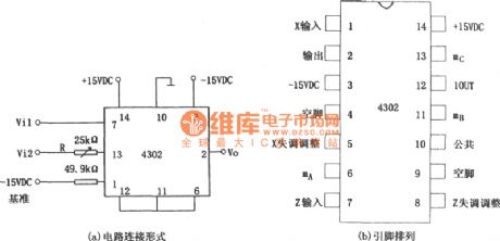
As shown in the figure is a multiplying circuit.
This circuit is composed of 4302, the relationship between input and output is :Vo=Vi1Vi2/10。
The main parameters of 4302:
(View)
View full Circuit Diagram | Comments | Reading(544)
The SIPMOS transistor push-pull control circuit
Published:2011/7/11 2:25:00 Author:TaoXi | Keyword: SIPMOS, transistor, push-pull, control
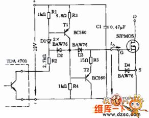
Figure:The SIPMOS transistor push-pull control circuit
(View)
View full Circuit Diagram | Comments | Reading(694)
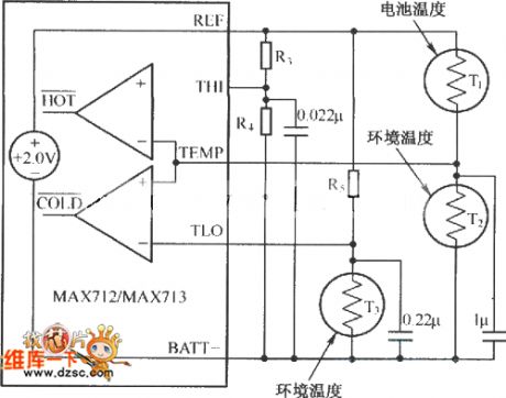
MAX712/MAX713 temperature control typical circuit
Published:2011/7/11 2:24:00 Author:TaoXi | Keyword: temperature control, typical
View full Circuit Diagram | Comments | Reading(643)
NE5565 electronic ballast controller
Published:2011/7/13 23:12:00 Author:TaoXi | Keyword: electronic ballast, controller
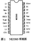
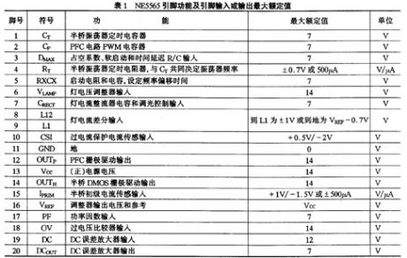

The NE5565 is designed as one kind of electronic ballast controller which is produced by the PHILIPS company. This kind of bipolar type single chip IC integrates the power factor correction (PFC) controller and the self-oscillating half-bridge drive which has the various control and protection functions. By using the NE5565 to design the fluorescent electronic ballast, we can reduce the component number, the volume, the weight and improve the reliability and safety of the ballast.
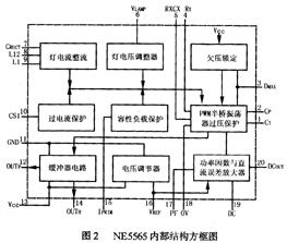
1. The internal structure and the main features of the NE5565
The NE5565 controller has two switching power supply circuits: the first one is the PFC boost converter controller, it improves the electronic ballast power factor to higher than 0.99, and the current harmonic distortion is extremely low, at the same time it supplies the protection for the AC transient voltage; the second one is the half-bridge oscillator circuit.
(View)
View full Circuit Diagram | Comments | Reading(718)
| Pages:196/312 At 20181182183184185186187188189190191192193194195196197198199200Under 20 |
Circuit Categories
power supply circuit
Amplifier Circuit
Basic Circuit
LED and Light Circuit
Sensor Circuit
Signal Processing
Electrical Equipment Circuit
Control Circuit
Remote Control Circuit
A/D-D/A Converter Circuit
Audio Circuit
Measuring and Test Circuit
Communication Circuit
Computer-Related Circuit
555 Circuit
Automotive Circuit
Repairing Circuit