
Index 191
Temperature controller 8
Published:2011/7/25 21:51:00 Author:Ecco | Keyword: Temperature controller
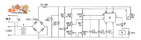
The temperature controller circuit is composed of the power supply circuit and temperature detection control circuit, and it is shown as the chart. Power supply circuit is composed of the power transformer T, rectifier diodes VD1 ~ VD4, resistors RI, power indicator LED VL1, filter capacitor C1 and Zener VS and so on. Temperature detection control circuit consists of thermistor RT, time-base integrated circuit IC, potentiometers RP1 ~ RP4, resistors R2 ~ R4, capacitors C2 ~ CZ, relay Kl, diode VD5 and light emitting diode VL2.
(View)
View full Circuit Diagram | Comments | Reading(646)
Temperature controller 9
Published:2011/7/25 21:54:00 Author:Ecco | Keyword: Temperature controller
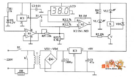
The temperature controller circuit is composed of the power supply circuit, temperature detection / display circuit, reference voltage circuit and control circuit, and it is shown as the chart. Power supply circuit is composed of the power switch S2, power transformer T, rectifier diodes VD2 ~ VD5, filter capacitors C1, C2, three-terminal voltage regulator integrated circuit IC3, resistors R6 and power indicator LED VL1. Temperature detection / display circuit is composed of the temperature sensor integrated circuit IC1, the control switch S1 and LCD display.
(View)
View full Circuit Diagram | Comments | Reading(687)
Timing controller circuit diagram 3
Published:2011/7/26 2:04:00 Author:Ecco | Keyword: Timing controller

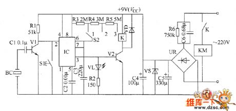
The timing controller circuit is composed of the power supply circuit and timing control circuit, and it is shown as the chart. Power supply circuit is composed of the power control button S1, normally open contact K1 of relay K, buck capacitor C1, discharge resistor R1, rectifier diodes VD1 ~ VD4, filter capacitor C2 and zener diode VS. Timing control circuit is composed of the time-base integrated circuit IC, delaying time selection switch S2, resistors R2 ~ R5, capacitors C3, C4, light-emitting diode VL, relay K and diode VD5.
(View)
View full Circuit Diagram | Comments | Reading(725)
Timing controller circuit diagram 4
Published:2011/7/26 2:08:00 Author:Ecco | Keyword: Timing controller
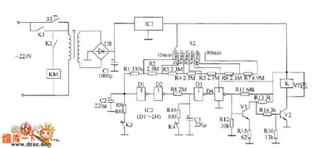
The timing controller circuit is composed of the power supply circuit, input control circuit, timing circuit and output control circuit, and it is shown as the chart. The power supply circuit is composed of the step-down capacitor C6, discharge resistor R6, bridge rectifier UR, filtering capacitors C5, C4 and the voltage regulator diode VS. The input control circuit is composed of the piezoelectric ceramic BC on electronic alarm clock, capacitor C1, resistors RI, transistor VI. Timing circuit consists of resistors R1 ~ R5, reset button S1, regular timing switch S2, capacitors C2 and C3, light-emitting diode VL, time-based integrated circuit IC.
(View)
View full Circuit Diagram | Comments | Reading(647)
Timing controller circuit diagram 5
Published:2011/7/26 2:12:00 Author:Ecco | Keyword: Timing controller
The timing controller circuit is composed of the power regulator circuit, timing time selection circuit, Schmitt trigger circuit and delay control circuit, and it is shown as the chart. Power regulator circuit consists of the start button S1, power transformer T, bridge rectifier UR, filter capacitor C1 and three-terminal voltage regulator integrated circuit IC1. Timing time is composed of selector switch S2, resistors R1 ~ R7. R1 ~ R16 select the 1/4W carbon film resistors. VD chooses the 1N4148 silicon switch diode.
(View)
View full Circuit Diagram | Comments | Reading(694)
Timing controller circuit diagram 6
Published:2011/7/26 2:15:00 Author:Ecco | Keyword: Timing controller

The timing controller circuit is composed of the power supply circuit, timing control circuit and control implementation circuit, and it is shown as the chart. Power supply circuit is composed of the power switch S1, fuse FU, power transformer T, rectifier diodes VD1 ~ VD4, filter capacitors C4, C5, and three-terminal voltage regulator integrated circuit IC1. Timing controller circuit is composed of the time-base circuits IC2, IC3, resistors R1 ~ R1O, capacitors C1 ~ C3, potentiometers RP1, RP2, transistors V1 ~ V4, light-emitting diodes VL1, VL2, manual discharge button S2 and function selector switch S3.
(View)
View full Circuit Diagram | Comments | Reading(748)
Primary timing controller 1
Published:2011/7/26 2:58:00 Author:Ecco | Keyword: primary timing controller
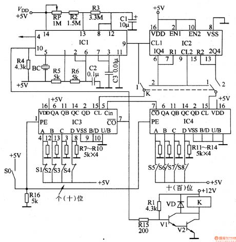
The primary timing controller circuit consists of the clock generator, divider, programming unit, driver controller and alarm, etc., and it is shown in Figure 3-83. Clock generator circuit is composed of an internal time-base circuit of the dual time-base integrated circuit ICl and the resistors R2 and R3, potentiometer RP, capacitor Cl and so on. Divider is a dual decade counter integrated circuit IC2. Programmer is reversible counter IC IC3, and 1C4 take into decimal subtraction counter IC. Drive control circuit consists of transistors Vl and V2, resistors Rl5 and Rl, diode VDl and relay K.
(View)
View full Circuit Diagram | Comments | Reading(1662)
Primary timing controller 2
Published:2011/7/26 3:01:00 Author:Ecco | Keyword: Primary timing controller
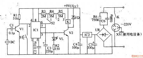
The timing controller circuit consists of the power supply circuit, input control circuit, timing circuit and output control circuit and other components, and it is shown in Figure 3-84. The power supply circuit is composed of step-down capacitor C6, resistor R6, bridge rectifier UR, filtering capacitors C5, C4 and three terminal integrated voltage regulator IC2. Input control circuit consists of the capacitor Cl, transistor Vl, resistor Rl and switch Sl. Timing circuit consists of the time-base integrated circuit ICl and the external components. Output control circuit consists of transistor V2, relay K and diode VD and other components.
(View)
View full Circuit Diagram | Comments | Reading(900)
Primary timing controller 3
Published:2011/7/26 3:04:00 Author:Ecco | Keyword: Primary timing controller
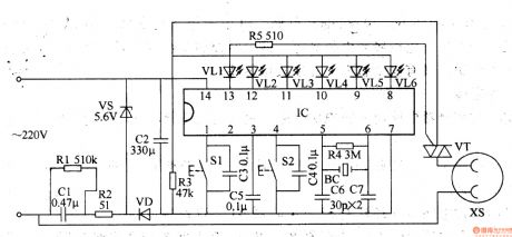
The primary timing controller circuit is composed of the power supply circuit and timing control circuit, and it is shown in Figure 3-85. Step-down power supply circuit is composed of the capacitor Cl, resistors Rl, R2, voltage regulator diodes VS, rectifier diode VD and filter capacitor C2. Timing control circuit consists of lC, control buttons Sl, S2, capacitors C3-C7, resistors R3-R5, quartz crystal oscillators BC, thyristor VT and light-emitting diodes VLl-VL6. Rl and R5 select the 1/2W carbon film resistors or metal film resistors.
(View)
View full Circuit Diagram | Comments | Reading(882)
Primary timing controller 4
Published:2011/7/26 3:07:00 Author:Ecco | Keyword: Primary timing controller

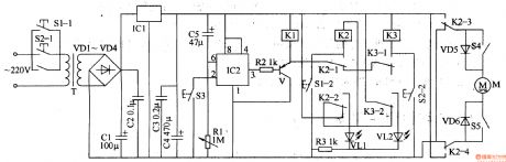
The primary timing controller circuit is composed of the power regulator circuit, timing time selection circuit, Schmitt trigger control circuit and delay circuit, and it is shown in Figure 3-86. Power supply regulator circuit consists of the start button Sl, power transformer T, bridge rectifier UR, filter capacitor Cl and three-terminal voltage regulator integrated circuit ICl. Timing time selection circuit is composed of selector switch S2 and resistors Rl-R7. Delay circuit consists of capacitors C2, C3, resistors R9, RlO, normally closed contacts K3, K4 of relay K and NOT gate integrated circuit IC2 (Dl-D4).
(View)
View full Circuit Diagram | Comments | Reading(719)
Electric curtain controller 1
Published:2011/7/26 2:27:00 Author:Ecco | Keyword: Electric curtain controller
The electric curtain controller circuit is composed of the power supply circuit, timer circuit, interlock switching circuit and overtravel-limit switch control circuit, it is shown as Figure 3-126. Power supply circuit is composed of button switches S1-1, S2-1, power transformer T, rectifier diodes VD1-VD4, capacitors C1-C4 and three-terminal voltage regulator integrated circuit ICl and so on. The timer circuit is composed of the time-base timer IC IC2, capacitor C5, resistors Rl, R2, transistor V and relay Kl. Interlock switch circuit is composed of the relay K3, and switches S1-2, S2-2, S3 and so on.
(View)
View full Circuit Diagram | Comments | Reading(1472)
Electric curtain controller 2
Published:2011/7/26 2:30:00 Author:Ecco | Keyword: Electric curtain controller
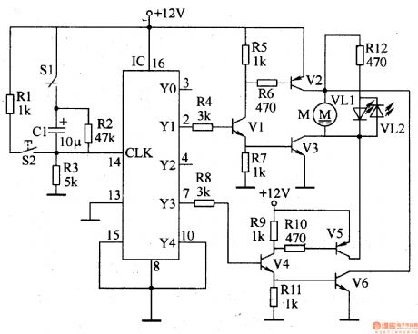
The electric curtain controller circuit is composed of the working status indication circuit, control circuit and motor drive circuit, and it is shown as Figure 3-127. Control circuit is composed of the slider switch S1, button S2, decimal counter IC and the external components. Motor drive circuit is composed of the motor M, drive transistors Vl-V6 and resistors R4-Rll. Resistor Rl2 and light-emitting diodes VLl, V form a working status indication circuit. Rl-Rl2 select 1/4W carbon film resistors.
(View)
View full Circuit Diagram | Comments | Reading(2050)
Electric curtain controller 3
Published:2011/7/26 2:34:00 Author:Ecco | Keyword: Electric curtain controller
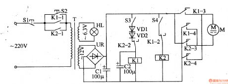
The electric curtain controller circuit is composed of the power supply circuit, switching circuit and other components, and it is shown in Figure 3-128. Power supply circuit consists of the power transformer T, bridge rectifier UR and filter capacitor Cl. Relays Kl, K2 and limit switch S3 form the interlocking power supply polarity switching circuit. M is the drive motor, HL is the light. Sl (CKDA) and S2 (moving together) is the button. Cl, C2 select the aluminum electrolytic capacitors with the voltage in 25V. S1, S2 select the small-scale micro-button switch.
(View)
View full Circuit Diagram | Comments | Reading(668)
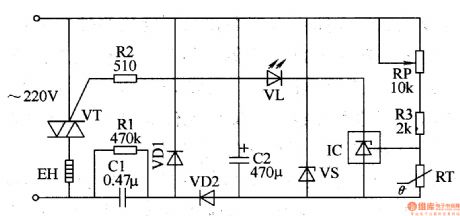
Temperature controller circuit diagarm 1
Published:2011/7/25 22:16:00 Author:Ecco | Keyword: Temperature controller
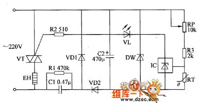
The power supply circuit is composed of the step-down capacitor C1, discharge resistor RI, rectifier diodes VD1, YD2, filter capacitor C2 and zener diode VS. Temperature detection control circuit is composed of the thermistor RT, resistors R2, R3, potentiometer RP, light-emitting diode YL, three-terminal precision regulator integrated circuit IC and thyristor VT. RI selects the l/2W metal film resistor: R2 and R3 select the l/4W metal film resistor. RP uses the multi-turn potentiometer. vs uses the 2DW7 silicon zener diode.
(View)
View full Circuit Diagram | Comments | Reading(707)
Temperature controller 5
Published:2011/7/25 21:39:00 Author:Ecco | Keyword: Temperature controller
The temperature controller circuit is composed of the power supply circuit and temperature detection control circuit, and it is shown as the chart. Power supply circuit is composed of the power switch S, fuse FU, power transformer T, rectifier diodes VD1 ~ VD4, three-terminal voltage regulator integrated circuit IC1, resistors RI and limiting resistor RI, power indicator LED VL1. Temperature detection control circuit is composed of the temperature sensing diode VD5, potentiometer RP, electronic switch integrated circuit IC2, relay K, diode VD6, resistor R2 and LED VL2.
(View)
View full Circuit Diagram | Comments | Reading(601)
Temperature controller circuit diagarm 2
Published:2011/7/25 22:19:00 Author:Ecco | Keyword: Temperature controller
Power supply circuit is composed of the power switch s, fuse FU, power transformer T, rectifier diodes VD1 ~ VD4, filter capacitor C1 and three-terminal regulator integrated circuit IC1. Temperature detection control circuit is composed of the thermistor RT, voice control integrated circuit IC2, transistor V, relay K, capacitors C2, C3, resistors RI ~ R3 and LEDs YL1, VL2. RI uses the 1/4W carbon film resistor or metal film resistor; R2 and R3 select the 1/2W carbon film resistors.
(View)
View full Circuit Diagram | Comments | Reading(677)
Electric heating appliance temperature controller 1
Published:2011/7/26 2:40:00 Author:Ecco | Keyword: Electric heating appliance , temperature controller
The electric heating apparatus temperature control circuit is composed of the power supply circuit and temperature detection control circuit, and it is shown in Figure 3-76. Rl selects the 1/2W metal film resistor; R2 and R3 select 1/4W metal film resistors. RP uses the multi-turn potentiometer. RT uses NTC502 negative temperature coefficient thermistor, and the room temperature (25 ℃) resistance is about 5kΩ. Cl uses the polyester capacitor or CBB capacitor with voltage being greater than 400V; C2 select the aluminum electrolytic capacitor with voltage in 16V. VDl, VD2 choose the 1N4007 silicon rectifier diode.
(View)
View full Circuit Diagram | Comments | Reading(731)
Electric heating appliance temperature controller 2
Published:2011/7/26 2:42:00 Author:Ecco | Keyword: Electric heating appliance, temperature controller
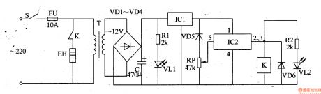
The electric heating apparatus temperature controller circuit is composed of the power supply circuit and temperature detection control circuit, and it is shown in Figure 3-77. Power supply circuit is composed of the power switch S, fuse FU, power transformer T, rectifier diodes VDl-VM, filter capacitor C, three-terminal voltage regulator integrated circuit ICl, current limiting resistor Rl and the power indicator LED VLl. Temperature detection control circuit is composed of the temperature sensing diode VD5, potentiometer RP, electronic switch integrated circuit IC2, relay K, diode VD6, resistor, saturated light-emitting diode VL2.
(View)
View full Circuit Diagram | Comments | Reading(631)
Electric heating appliance temperature controller 4
Published:2011/7/26 2:48:00 Author:Ecco | Keyword: Electric heating appliance , temperature controller
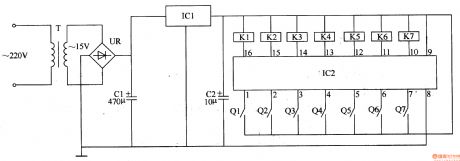
The electric heating apparatus temperature controller circuit is composed of the power supply circuit and temperature detection control circuit, and it is shown in Figure 3-79. Power supply circuit is composed of the power transformer T, bridge rectifier UR, filter capacitors Cl, C2, and three-terminal voltage regulator integrated circuit ICl. Temperature measurement control circuit consists of seven-segment LED digital integrated circuit IC2 and electric hot thermometers Ql-Q7, relays Kl-K7. Cl and C2 select the aluminum electrolytic capacitors with voltage in 25V.
(View)
View full Circuit Diagram | Comments | Reading(635)
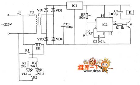
Electric heating appliance temperature controller 3
Published:2011/7/26 2:45:00 Author:Ecco | Keyword: Electric heating appliance, temperature controller
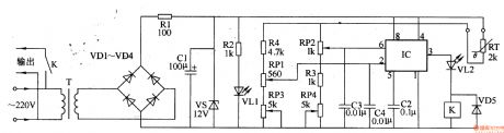
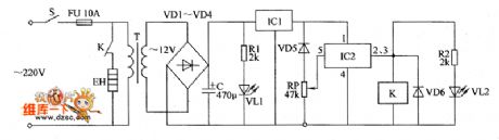
The electric heating apparatus temperature controller circuit is composed of the power supply circuit and temperature detection control circuit, and it is shown in Figure 3-78. Power supply circuit is composed of the power transformer T, rectifier diodes VD1-VD4, resistor B1, power indicator LED VL1, filter capacitor C1 and Zener VS. Temperature detection control circuit consists of thermistor RT, time-base integrated circuit IC, potentiometers RPl, RP2, resistors R2, R4, capacitors C2-C4, relay K1, diode VD5 and light-emitting diode VL2.
(View)
View full Circuit Diagram | Comments | Reading(708)
| Pages:191/312 At 20181182183184185186187188189190191192193194195196197198199200Under 20 |
Circuit Categories
power supply circuit
Amplifier Circuit
Basic Circuit
LED and Light Circuit
Sensor Circuit
Signal Processing
Electrical Equipment Circuit
Control Circuit
Remote Control Circuit
A/D-D/A Converter Circuit
Audio Circuit
Measuring and Test Circuit
Communication Circuit
Computer-Related Circuit
555 Circuit
Automotive Circuit
Repairing Circuit