
Index 198
Fast simulation switch circuit
Published:2011/5/12 2:24:00 Author:Nicole | Keyword: simulation switch
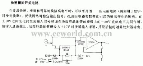
It requires fast, accurate and reliable to change the high level, it can adopt the circuit as shown(such as digital-synchronous converter). The feedback network can steadily output singal, it can counteract the influence of output changes due to the circuit parameter changes. Under the joint actions of AC input singal changes between ±10V and -20V DC voltage on the grid of FET, it makes input channel cut off. when the grid of FET is +10V, the input channel is turned on, then it is exported by the later operational amplifier. (View)
View full Circuit Diagram | Comments | Reading(696)
Control AC load interface circuit
Published:2011/5/12 2:18:00 Author:Nicole | Keyword: control AC load, interface
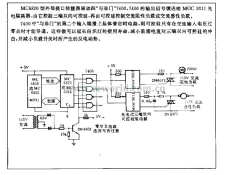
MC6820 external interface converter drives NAND gate 7400, 7400 output singal is fed to MOC3011 photoelectric isolator, it controls three terminal TRIAC which controls AC resistance load or AC inductive load.
To connect transistor timing circuit on the second input terminal of 7400 NAND gate , the TRIAC is on conduction only when the AC input voltage pass zero point. It can delay the usefil time of incandescent lamp, and reduce surge current to attack three terminal TRIAC, and decrease the back-EMF produced by load switch. (View)
View full Circuit Diagram | Comments | Reading(883)
DAC667 basic connection and output voltage set up
Published:2011/7/17 20:12:00 Author:zj | Keyword: basic connection, output voltage, set up

View full Circuit Diagram | Comments | Reading(568)
Phone busy indicator circuit2
Published:2011/7/6 19:58:00 Author:zj | Keyword: Phone busy indicator
View full Circuit Diagram | Comments | Reading(561)
Long distance telephone ringing circuit
Published:2011/7/20 2:35:00 Author:zj | Keyword: Long distance, telephone ringing
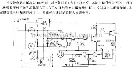
When voltage ofringing circuit is more than 100 V , the two neon light H1 and H2 will be lighted.The output signal will add to VT1、VT2 after rectifiering by VD1~VD4.Then it will add to Optoelectronic coupler IC1,control theconduction of TRIAC.Thus the ac voltage can be added to the socket J, the load will access ac voltagethrough the plug. (View)
View full Circuit Diagram | Comments | Reading(681)
LCl82 audio voltage control neon light pattern control circuit
Published:2011/5/10 7:41:00 Author:Nicole | Keyword: audio voltage control, neon light pattern
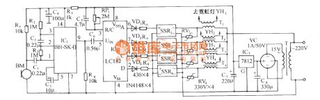
The control circuit is as shown. It consists of pickup sensor, sound control integrated circuit IC1, LC182 light control circuit, AC solid state relay and neon light drive circuit, AC depressurization rectifier circuit. Sensor BM is CRZ2 electret condenser microphone, it will transform the piched up sound singal into electrical signal. IC2 adopts special sound control integrated circuit BH-SK-II. Its chip contains three-level amplifier, shaper, frequency selection network, bistable trigger and drive circuit. The singal from sensor BM is added to input terminal 1 foot of SK-Ⅱsecond level amplifier through C1, after enlarged, it is outputed by 2 foot, and coupled to the input terminal 3 foot of SK-Ⅱthird level amplifier, it is enlarged and shaped again, it is fliped by triggering bistable state. SK-Ⅱhas two drive output terminals of 6 foot, 9 foot, it only uses output current terminal 9 foot as output. Outputed by SK-Ⅱ, The pulse singal is added to LC182 audio frequency singal input terminal UIN through C6. The sound(such as hand-clapping, beating) singal and the flipping of SK-Ⅱbistable state circuit is controlled by sensor BM, then to control the voltage control oscillator frequency inside SK-Ⅱ, it can realize voltage control to the cycle flashing frequency of color lamp. (View)
View full Circuit Diagram | Comments | Reading(821)
Thermal furnace temperature regulating circuit
Published:2011/5/9 8:59:00 Author:Nicole | Keyword: furnace, temperature regulating
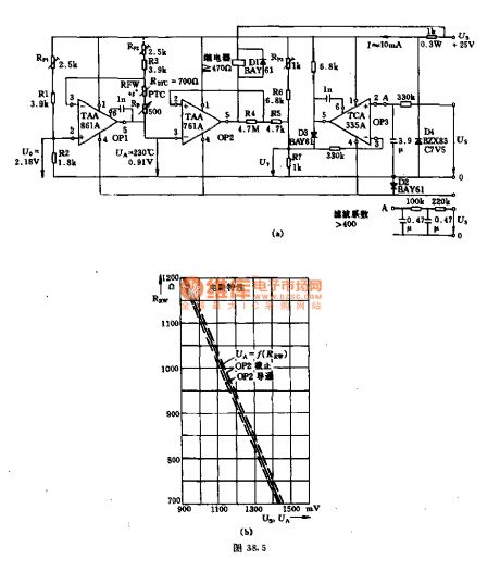
In general regulating circuit, the waste heat sensor is used as voltage divider, it is hard to obtain good linear relationship. The figure (a) may have linear relationship. A few waste heat devices can be controlled by a external control device, then it will produce a DC voltage which has relation with external condition, the value is between 0.91~1.43V. In figure (a), the input terminal 2 switch voltage U7 of operational amplifier OP2 is controlled by the attenuation ratio: RP3+R6/R7, it is about 0.91V, when the control voltage Us=0.
The figure (b) is a performance curve of circuit. When control voltage Us≦0.91V, hysteresis loop is about 20%, because the resistance R7 is in action in this region. (View)
View full Circuit Diagram | Comments | Reading(749)
High limit of temperature animal bleating alarm and automatic ventilation cooling control circuit
Published:2011/5/16 3:50:00 Author:Nicole | Keyword: temperature, bleating alarm, ventilation cooling
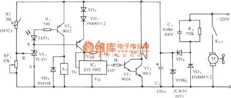
The circuit is as shown, it consists of upper temperature limit detection circuit, call alarm circuit, relay control fan lowering temperature circuit and AC depressurization power supply circuit. IC1 adopts CMOS large scale language integrated circuit KD-56021, it stores four kinds of animal sounds: sheep, cattle, chicken, dog. (View)
View full Circuit Diagram | Comments | Reading(599)
Dark room hand touch control circuit
Published:2011/5/17 2:36:00 Author:Nicole | Keyword: dark room, hand touch
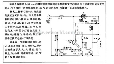
Two helical or mesh electrodes with 1.58mm spacing are fixed in the bulb table or any other convenient places in dark room, when the hand touches the electrode one time, the 180W bulb turns on, if the hand touches it again, the bulb will turn off.
The AC power is changed into DC power by rectifier diode GE504A, it is fed to Q1, Q2. When the hand touches mesh electrode, the Q1 base circuit is turned on, then Q1 is conduction, Q2 turns off, in the positive half cycle of AC power, SCR turns on, 180W bulb is lightened, L1 6W small bulb is lightened too, L1 illuminates Q1, it keeps Q1 conductive, Q2 is turned off, although the hand has been left the electrode, the bulb is still shining.
If your hand touches mesh electrode again, then Q1 base turns on, the carrier which is produced by L1 shining on Q1 will be released from R6, R7, then Q1 is cut off, Q2 is turned on, SCR is not turned on, 180W and 6W bulbs are all died out. (View)
View full Circuit Diagram | Comments | Reading(619)
Flashing alarm circuit
Published:2011/5/13 3:59:00 Author:Nicole | Keyword: Flashing alarm
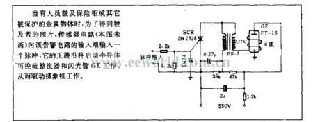
When somebody touches the safety cabinet or other protected metallic objects, in order to obtain the toucher's photo, sensor circuit will input a pulse to the input terminal of this alarm circuit, its positive edge will start the semiconductor SCR rectifier and flashtube GE to work, then to drive the video camera to work. (View)
View full Circuit Diagram | Comments | Reading(614)
Municipal electric power over-voltage, under-voltage automatic indication protection circuit
Published:2011/5/13 3:56:00 Author:Nicole | Keyword: municipal electric power, over-voltage, under-voltage
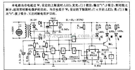
When the municipal electric power is higher than the upper limit which is set by W1, LED2 is lightening, gate 2 is latched, outputing 1 , J pulls in, NC contact cuts off, to fulfill the purposes of power-off protection. When mains supply is lower than the lower limit value set by W2, gate 4 opens, LED1 is on, gate 3 outputs 0 , then J pulls in, it also can protect current failure. (View)
View full Circuit Diagram | Comments | Reading(604)
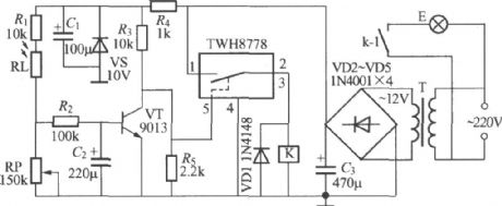
Light control street lamp circuit using TWH8778 (1)
Published:2011/7/13 20:35:00 Author:zj | Keyword: Light control, street lamp circuit
View full Circuit Diagram | Comments | Reading(613)
CS4340 audio D/A transformation integrated circuit diagram
Published:2011/5/16 3:22:00 Author:Nicole | Keyword: audio, D/A transformation

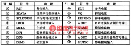
CS4340 is a two-channel D/A transformation integrated circuit with 24 bit resolution which are produced by crystal company, it is widely used in DVD player.
CS4340 integrated circuit internally installs serial output interface circuit, interpolation filter, △∑D/A and analogue filter, deemphasis circuit and squelch circuit. It is used to change the audio data singal into analogue singal, it supports 32/44.1/44/96KHz and many kinds of sampling frequency. The internal circuit block diagram of integrated package is shown as figure1, it adopts 16-foot packaging, the pin function of integrated circuit is shown in chart1.
Figure1,the internal circuit block diagram of C54340 integrated package is shown
Chart1,the pin function of C54340 integrated circuit is shown (View)
View full Circuit Diagram | Comments | Reading(773)
KA9256-two-way power drive integrated circuit diagram
Published:2011/5/6 1:17:00 Author:Nicole | Keyword: two-way power drive
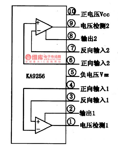
KA9256 is a two-way power drive integrated circuit diagram which is produced by South Korea's Samung, it is widely used in CD player(especially in car CD player) and videodisc player, it is as drive spindle motor, it feeds to motor or load motor.
1, KA9256 internal circuit block diagram and pin function
The internal of manifold block KA9256 is composed of two-way same function power drive circuit, when the power voltage VCC=±15V, the maximum output current is about 1A. It adopts 12-foot in-line package, the internal circuit and pin function of the integrated block is shown as figure1-1.
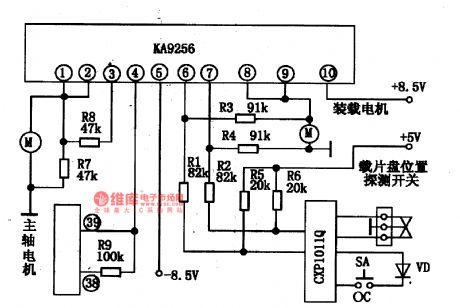
2, KA9256 typcial application circuit
The typcial application circuit of KA9256 integrated block is shown as figure1-2.
Figure1-2, the internal circuit and pin function of KA9256 integrated block is shown.
Figure 1-2, the typcial application circuit of KA9256 integrated block is shown
(View)
View full Circuit Diagram | Comments | Reading(1943)
The motorcycle anti-theft alarm (2)
Published:2011/7/19 19:21:00 Author:TaoXi | Keyword: motorcycle, anti-theft, alarm
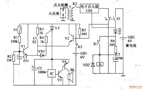
The multi-function motorcycle anti-theft alarm is introduced in this article, and it can be used in the anti-theft applications of all the two-wheel motorcycles.
The principle of the circuit
The motorcycle anti-theft alarm circuit is composed of the mobile delay alarm circuit, the ignition switch ground wire break alarm circuit, the right cover vandal resistant alarm circuit, the control circuit, the alarm signal generating circuit and the power-saving circuit, as the figure 7-85 shows.
The mobile delay alarm circuit is composed of the mercury switch Sl, the resistors Rl and R2, the delay capacitor Cl and the transistor Vl.etc.
(View)
View full Circuit Diagram | Comments | Reading(2392)
Short Circuit or Input Back Protected Circuit Operating Only When Input Voltaged is Provided
Published:2011/7/19 2:04:00 Author:Joyce | Keyword: Short Circuit , Input Back , Protected, Input Voltaged , Provided
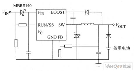
The circuit is protected from short circuit and input back. If the inductance value chosen will not be supersaturated, reducing voltage stabilizer LT3481 is able to withstand short cut of the output. But here’s another condition in the system to consider, that is when LT3481 has no input, the output will still maintain a high level. When the battery is charging or in battery backup systems, it may happen if the battery or any other power supply is connected with LT3481 by diode or (OR). If the end FIN is allowed to float, and end RUN / SS is connected with end VIN by a logic signal while keeping high level, the static current in internal circuit of LT3481 will be drawn through the end SW.
(View)
View full Circuit Diagram | Comments | Reading(539)
Brightness automatic control circuit
Published:2011/7/19 8:15:00 Author:Fiona | Keyword: automatic control
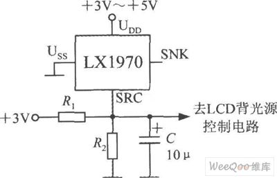
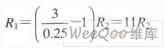
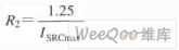
When the ambient brightness turns dark obviously,LX1970 can automatically turn the LCD backlight to make white LED light.Brightness automatic control circuit is shown as above.Using resistors R1 and R2 can set to control the brightness's minimum and maximum.Changing the capacity of capacitor C the capacity can adjust the response time and filter out 50 Hz power grid interference.LX1970 uses +3.3 ~ +5 V power supply.When only using SRC end,SNK end should be hung in the air.Assumed that the circuit requires 0.25 ~ 1.25V output voltage to drive the white LED,0.25V represents the minimum of LED brightness,1.25V represents the brightness's maximum.
(View)
View full Circuit Diagram | Comments | Reading(722)
A Capacitive Load Emitter Follower Circuit
Published:2011/7/18 10:27:00 Author:Robert | Keyword: Capacitive Load, Emitter, Follower
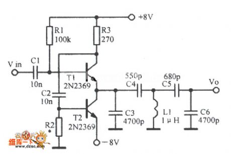
The picture shows thea capacitive load emitter follower circuit. (View)
View full Circuit Diagram | Comments | Reading(727)
Over-Voltage And Over-Current Protection Circuit Which Meets Any Stabilized Voltage Supply
Published:2011/7/18 9:32:00 Author:Robert | Keyword: Over-Voltage, Over-Current, Protection, Stabilized Voltage Supply
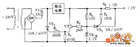
The picture shows the over-voltage and over-current protection circuit which meets any stabilized voltage supply. (View)
View full Circuit Diagram | Comments | Reading(695)
Multi-Channel Corded Remote-Control Switch Circuit
Published:2011/7/18 9:34:00 Author:Robert | Keyword: Multi-Channel, Corded, Remote-Control, Switch
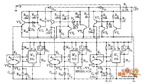
The picture shows the multi-channel corded remote-control switch circuit. (View)
View full Circuit Diagram | Comments | Reading(811)
| Pages:198/312 At 20181182183184185186187188189190191192193194195196197198199200Under 20 |
Circuit Categories
power supply circuit
Amplifier Circuit
Basic Circuit
LED and Light Circuit
Sensor Circuit
Signal Processing
Electrical Equipment Circuit
Control Circuit
Remote Control Circuit
A/D-D/A Converter Circuit
Audio Circuit
Measuring and Test Circuit
Communication Circuit
Computer-Related Circuit
555 Circuit
Automotive Circuit
Repairing Circuit