
Index 187
CLOSED_LOOP_ALARM
Published:2009/6/14 21:40:00 Author:May
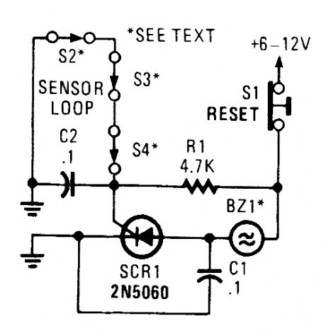
A string of three series-connected, normally closed switches are connected across the gate of an SCR. When one opens, the SCR triggers via R1, sounding an alarm. The alarm should be of the noninterrupting type. (View)
View full Circuit Diagram | Comments | Reading(1024)
WARBLE_ALARM
Published:2009/6/14 21:50:00 Author:May
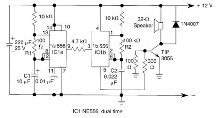
This circuit uses a 556 to first generate a low frequency square wave, that is modulated to pro-duce two alternate tones of about 400 and 500 Hz. Circuit generates warble alarm of European emer-gency vehicles. The frequencies of the oscillators are determined by the values of R1, C1 and R2, C2. (View)
View full Circuit Diagram | Comments | Reading(962)
DELAYED_ALARM
Published:2009/6/14 21:42:00 Author:Celina
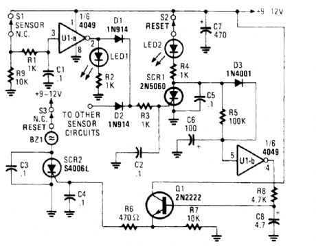
The alarm/sensor circuit shown is built around two SCRs, a transistor, a 4049 hex inverter, and a few support components, all of which combine to form a closed-loop detection circuit with a delay feature. The delay feature allows you to enter a protected area and deactivate the circuit before the sounder goes off.Assuming that the protected area has not been breached (i.e., S1 is in its normally-closed posi-tion), when power is first applied to the circuit, a positive voltage is applied to the input of UI-a through 51 and RI, causing its output to go low. That low is applied to the gate of SCR1, causing it to remain off. At the same time, C6 rapidly charges toward the +Tsupply rail through S2, LED2, R4, and D3. The charge on C6 pulls pin 5 of UI-b high, causing its output at pin 4 to be low. That low is ap-plied to the base of Q1, keeping it off. Because no trigger voltage is applied to the gate of SCR2 (via Q1), the SCR remains off and BZ1 does not sound.But should S1 open, the input of UI-a is pulled low via R9, forcing the output of UI-a high, light-tng LED1. That high is also applied to the gate of SCR1 through Dl and R3, causing SCR1 to turn on.With SCR1 conducting, the charge on CG decays, the input of UI-b at pin 5 is pulled low, forcing its output high, slowing charging C8 through R8 to a voltage slightly less than the positive supply rail.Transistor Q1 remains off until C8 has charged to a level sufficient to bias Q1 on, allowing suffi-cient time to enter the protected area and disable the alarm before it sounds. Once C8 has developed a sufficient charge, Ql turns on and supplies gate current to SCR2 through R6, causing the SCR to turn on and activate BZ1. If the circuit is reset before the delay has timed out, no alarm will sound.The delay time can be lengthened by increasing the value of either or both C6 and R5; decreas-tng the value of either or both of those components will shorten the delay time.All of the switches used in the circuit are of the normally-closed (NC) variety. Switch 51 can be any type of NC security switch. Switch 52 can be either a pushbutton or toggle switch. Because 53 is used to disable the sounder (BZl) only, anything from a key-operated security switch to a hidden toggle switch can be used. (View)
View full Circuit Diagram | Comments | Reading(1325)
NUCLEAR_REACTOR_STARTUP_CONTROL
Published:2009/7/13 1:05:00 Author:jailer


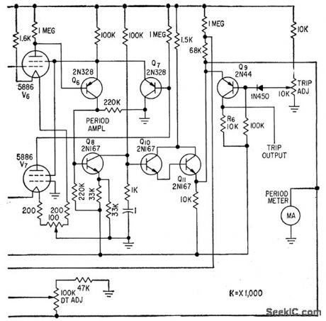


Logarithmic and period amplifers provide required wide indicating range without switching. Use of log diode V1 in series bock to back with V2 provides nonlinear element in which effects of changes in cathode temper ature and supply voltage are balanced out.V1 drives log amplifier consisting of balanced electrometer tubes V3 and V4, differential stage Q1-Q2, and cascaded emitter-followers Q3 and Q4. Period ampliler is a feedback-type differentiating circuit.-E. J. Wade and D.S. Davidson, Transistor Amplifers for Reactor Controls, Electronics, 32:21,p52-53. (View)
View full Circuit Diagram | Comments | Reading(942)
Hatch temperature controller circuit diagram
Published:2011/6/28 2:13:00 Author:Rebekka | Keyword: Hatch temperature controller
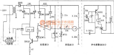
The figure shows the hatch temperature control circuit. This circuit is composed of the temperature detection circuit, temperature control circuit and power outages alarm circuit etc. The temperature measurement circuit is an unbalanced bridge, and it uses gauge head A for instructions. The electric bridge is a negative temperature coefficient and has high sensitivity MF51 thermal resistor. Along with the hatch of the temperature in the cabinet constant temperature is different, the resistance of the MF51 changes. The potential of corresponding bridge two points A and B changes. It passes the 50 ttA magnetoelectric meter pointer to reflect the change of the temperature changes. (View)
View full Circuit Diagram | Comments | Reading(682)
Variable threshold over-current and over voltage protection circuit diagram
Published:2011/5/12 21:47:00 Author:Rebekka | Keyword: Over-current protection, over voltage protection
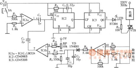
The circuit will set the corresponding reference threshold for effective protection of the load depending on the actual voltage and current of the load. The whole circuit is composed of over current, over voltage detection, signal amplifier and control signal output circuit, manual start, stop control circuit and thyristor trigger circuit. (View)
View full Circuit Diagram | Comments | Reading(1541)
Monolithic over and under voltage protection circuit diagram
Published:2011/5/12 21:34:00 Author:Rebekka | Keyword: Monolithic over and under voltage protection
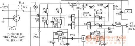
The over and under voltage protection circuit is composed of the six Schmitt trigger CD4584 . When it is over-voltage or under voltage. The circuit will sound siren and cut off the working power supply of the controlled circuit by relay. (View)
View full Circuit Diagram | Comments | Reading(2858)
Cable radio and amplifier protector circuit diagram
Published:2011/5/16 4:07:00 Author:Rebekka | Keyword: Cable radio , amplifier protector
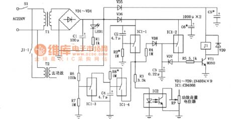
The high-power amplifiers radio used in the broadcast room of cable radio towns in rural areas is easily damaged. The reasons are: The frequent use, non-service management, the radio is often shut down when it works in the maximum volume state or the radio is started in the whole input power. This kind of amplifiers radio is arge output transformer output. There are are many transformers in the circuit. The peak inverse voltage maybe breakdown amplifier tube when you turn on or turn off the machine. The peak inverse voltage is caused by improper operation. The circuit can turn off the signal before the amplifier start to work. And it can also turn down the volume before the machine is turned off. So that the amplifier can be protected from damage. (View)
View full Circuit Diagram | Comments | Reading(718)
LCD projector multi-function controller circuit diagram
Published:2011/6/23 22:59:00 Author:Rebekka | Keyword: LCD projector multi-function controller
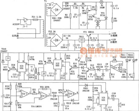
In the production of LCD projector, the main factors of the threatening life of LCD screen is the temperature of halogen. The multi-function controller made by this circuit is very effective for the protection of liquid crystal projector. The LCD projector multi-function controller circuit is shown as below. The circuit composed of VD1 ~ VD4, ICl, C1, VTl and other components provides a guarantee for the whole machine. The integral soft-start bulb circuit is composed of the VD5 VD8, C5, VT2, VT3 and other components. (View)
View full Circuit Diagram | Comments | Reading(5314)
The fermentation cylinder temperature alarm and controll circuit composed of the NE555
Published:2011/6/28 3:54:00 Author:Rebekka | Keyword: fermentation cylinder
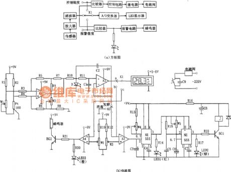
The alarming circuit is composed of comparator A4 and buzz circuit. When the temperature is more than 29 ℃, the A4 inverse end set potential compare with the A2 output. A4 outputs high level. The BG2 is conducted. It sounds bees alarm and at the same time the LED3 bright alarm lights (orange light) to remind the officer on duty to note out fault. It makes temperature control in the most suitable range. This circuit can make the temperature in 28 + 1 ℃, when the temperature is more than 29 ℃, the circuit will sound and light alarm signal to remind people. (View)
View full Circuit Diagram | Comments | Reading(717)
The ultrasonic back-up crashproof alarm (2)
Published:2011/7/22 22:45:00 Author:qqtang | Keyword: ultrasonic, crashproof alarm
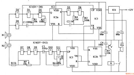
The working principle of the circuit The ultrasonic back-up crashproof alarm consists of the power supply circuit, ultrasonic emitting circuit, trigger circuit, low frequency oscillator, counter, ultrasonic reception process circuit and alarm circuit, see as figure 7-108.
The power supply circuit consist of the 3-terminal regulator integrated circuit IC6 and filter capacitors of C4 and C5.The ultrasonic emitting circuit consists of the emitter BI, the NOR gates D1-D4 inside the integrated circuit lC1(DI-D6), resistors of R1 and R2, resistor C1 and so on. (View)
View full Circuit Diagram | Comments | Reading(648)
The pulse delay circuit composed of gate circuit
Published:2011/6/29 2:58:00 Author:Rebekka | Keyword: pulse delay circuit , gate circuit
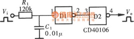
Pulse delay circuit will delay the output pulse that is relative to the input pulse for some time, but it will not change the width of the pulse. The main work principle of the circuit is to use the time delay function of the circuit. It delays the input pulse for a RC time. The figure shows the pulse delay circuit composed of gate circuit. (View)
View full Circuit Diagram | Comments | Reading(971)
The bicycle burglarproof alarm (1)
Published:2011/7/22 21:56:00 Author:qqtang | Keyword: burglarproof alarm
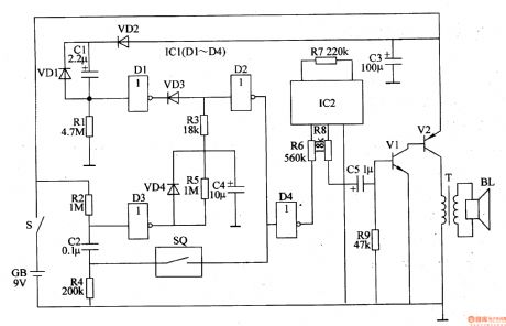
The working principle of the circuit The bicycle burglarproof alarm consists of the trigger control circuit and voice alarm circuit, see as figure 7-109.
The trigger control circuit consists of the sensor SQ, diodes VDl-VD4, resistors Rl-R6, capacitors of C1, C2, C4, NAND integrated circuit ICl(Dl-D4) and so on. The sound alarm circuit consists of the sound integrated circuit IC2, transistors V1 and V2, resistors R7-R8, capacitor C5, output transformer T and loudspeaker BL. (View)
View full Circuit Diagram | Comments | Reading(574)
The bicycle burglarproof alarm (2)
Published:2011/7/22 22:05:00 Author:qqtang | Keyword: burglarproof alarm
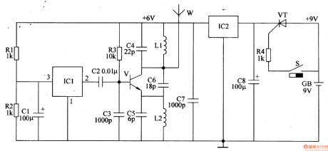
The working principle of the circuit The bicycle burglarproof alarm consists of the trigger control circuit, regulator filter circuit, music generator circuit and wireless emitting circuit, see as figure 7-110.
The trigger control circuit consists of the trigger switch S, resistor R4 and thyristor VT. The regulator filter circuit consists of the 3-terminal voltage regulator integrated circuit IC2 and resistors of C7 and C8. The music generator circuit consists of the resistors R1 and R2, capacitor C1 and 3-terminal music integrated circuit IC1. (View)
View full Circuit Diagram | Comments | Reading(616)
The electric air pressure switch
Published:2011/7/22 9:24:00 Author:qqtang | Keyword: air pressure switch
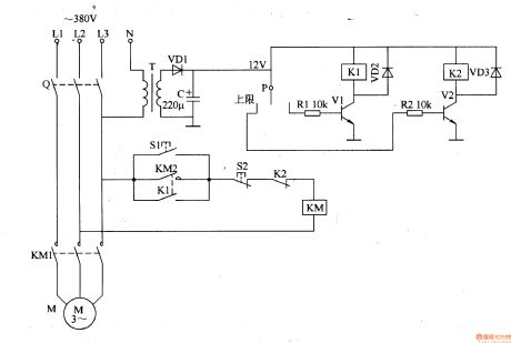
The working principle of the circuitThe electric air pressure switch circuit consists of the power supply circuit and pressure detecting control circuit, see as figure 8-129.
 The power supply circuit consists of the transformer T, rectifier diode VD1 and filter capacitor C.The pressure detection control circuit consists of the pressure meter P, resistors of R1 and R2, transistors of V1 and V2, relays of K1 and K2, diodes of VD2 and VD3. (View)
View full Circuit Diagram | Comments | Reading(2512)
The car engine over-temperature alarm
Published:2011/7/22 21:12:00 Author:qqtang | Keyword: over-temperature alarm
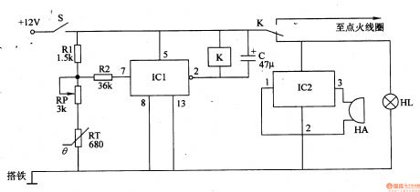
Here is to introduce the car engine over-temperature alarm which has the protection function, it can emitter alarm signal when the working temperature of the engine is too high and the temperature of the water tank is over 9O℃, at the same time, it will cut off the igniting power supply automatically to put out the engine.The working principle of the circuitThe car engine over-temperature alarm consists of the temperature detection control circuit and acousto-optic alarm circuit, see as figure 7-111.
(View)
View full Circuit Diagram | Comments | Reading(1639)
The 8-line inter-lock e-switch
Published:2011/7/22 9:13:00 Author:qqtang | Keyword: 8-line, inter-lock, e-switch
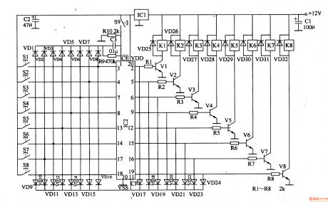
The working principle of the circuit This 8-line inter-lock e-switch circuit consists of the regulated filter circuit, input control circuit, lock storage circuit and the control executing circuit, see as figure 8-126.
The regulated filter circuit consists of the 3-terminal regulated integrated circuit IC1 and filter capacitors of C1 and C2。 The input control circuit consists control key Sl-S8 and diode VDl-VDl6. The lock storage circuit consists of 8 D trigger integrated circuits of IC2, reset key S9, resistors of R9 and R10, capacitor C3 and so on. (View)
View full Circuit Diagram | Comments | Reading(1381)
The light control safety switch
Published:2011/7/22 7:11:00 Author:qqtang | Keyword: light control, safety switch
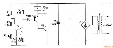
The working principle of the circuitThe light control safety switch circuit consists of the power supply circuit, light control circuit and control executing circuit(switch circuit), see as figure 8-128.
The power supply circuit consists of the power supply circuit T, rectifier bridge pile UR and filter capacitor C2.The light control circuit consists of the LDR RL, resistor Rl-R3, potentiometer RP, transistor V1 and capacitor C1.The control executing circuit consists of the diodes of VD1 and VD2, transistors V2 and V3, relay K and so on. (View)
View full Circuit Diagram | Comments | Reading(703)
The light control approaching switch circuit
Published:2011/7/22 9:33:00 Author:qqtang | Keyword: light control, approaching switch

The working principle of the circuitThe light control approaching switch circuit consists of the LDR RG, pressure sensitive resistor RV, transistors of V1 and V2, resistor Rl-R5, capacitors of C1 and C2, regulated diode VS, thyristor VT and diodes VDl-VD5, etc, see as figure 8-130.
Usually, RG is in a low LEV due to the light, V1 and V2 are both conducting, VT is blocked, the middle relay KA is in the releasing state, its normally closed contactor is conducting, the load is getting power and working. (View)
View full Circuit Diagram | Comments | Reading(627)
Numbers Padlock Integrated Circuit
Published:2011/7/14 7:06:00 Author:Sue | Keyword: Numbers, Padlock, Integrated
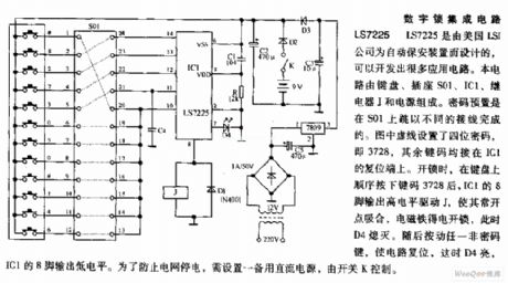
LS7225 is designed by American LSI company for automatic protective device, which can develop many application circuit. The circuit consists of keyboard, socket S01,IC1, relay J and power supply. The code preset is finished by connecting different wirings to S01. As seen in the figure, a four figures code is set, that is 3728, while other key codes are all on IC1's reset terminal. When to open the padlock, after pushing the key codes 3728 inproper order on the keyboard, IC1's pin 8 will output high level which will drive J to work which will make its normally open point connected. The electromagnet will get power to open the padlock, and D4 will go out. Then if any non-code key is pushed, the circuit will be reset and D4 is illuminated. IC1's pin 8 will output low level. In order to prevent the electrified wire netting from losing electricity, a spare current power is needed which is controlled by switch K. (View)
View full Circuit Diagram | Comments | Reading(911)
| Pages:187/312 At 20181182183184185186187188189190191192193194195196197198199200Under 20 |
Circuit Categories
power supply circuit
Amplifier Circuit
Basic Circuit
LED and Light Circuit
Sensor Circuit
Signal Processing
Electrical Equipment Circuit
Control Circuit
Remote Control Circuit
A/D-D/A Converter Circuit
Audio Circuit
Measuring and Test Circuit
Communication Circuit
Computer-Related Circuit
555 Circuit
Automotive Circuit
Repairing Circuit