
Index 197
High power factor, high efficiency electronic ballast controller ML4831
Published:2011/7/13 23:14:00 Author:TaoXi | Keyword: High power factor, high efficiency, electronic ballast, controller
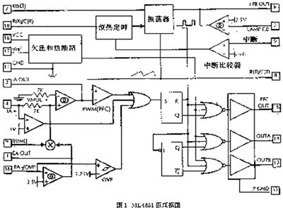
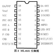
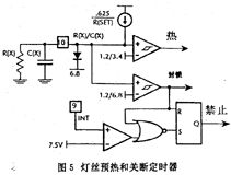
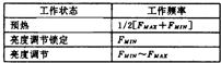
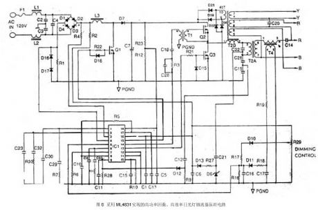
The ML4831 is designed as one kind of brightness adjustable high power factor, high efficiency electronic ballast controller. It is composed of the power factor controller, the oscillator, the preheat turn-off timing sequence, the control selective passing logic, the output driver and the over-voltage, over-temperature protection devices. The restarting and the lamp re-exporting are controlled by the external timing sequence, and considering the comprehensive control of the different tube characteristics, the ballast control device can adjust the lamp power through the frequency modulation (FM), it adjusts the lamp power and the operating frequency of the voltage-controlled oscillator (VCO) by compensating the programming. These functions are integrated on one chip, so this chip can be used in different occasions.
(View)
View full Circuit Diagram | Comments | Reading(1066)
Selection guides of the energy-saving lamps and electronic ballast transistor parameters
Published:2011/7/13 23:15:00 Author:TaoXi | Keyword: Selection guides, energy-saving lamps, electronic ballast, transistor, parameters
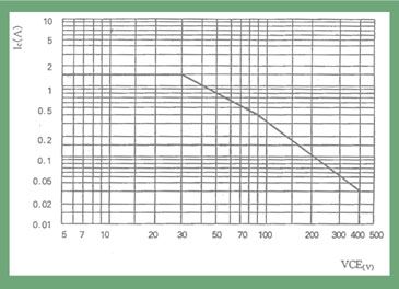
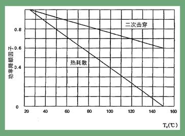
The power tolerance is a area which is surrounded by the curve (figure 1), when the voltage and current coordinate values of the transistor are over the range of the curve, the transistor will occur the power breakdown and it will be damaged. In practical applications, some switching power supply line loads are sensitivity, after the transistor is cut off, the self-inductance potential anti-peak voltage which is produced by the inductive load adds between the C pole and E pole of the transistor, so the transistor need to have enough SOA, BVceo and BVcbo values to bear the back voltage.
(View)
View full Circuit Diagram | Comments | Reading(586)
Three-phase and Six-step Motor Control Circuit of MC33035
Published:2011/7/13 7:06:00 Author:Michel | Keyword: Three-phase, Six-step, Motor Control Circuit
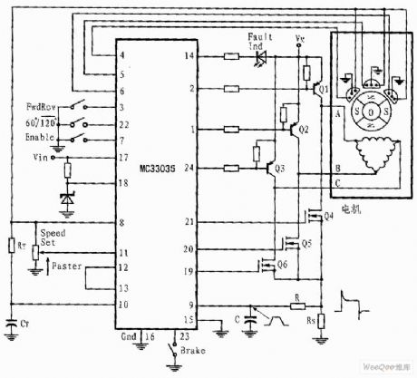
The shown three-phase application circuit owns motor controller circuit connection diagram which is driven by full wave six-step.The power switch triode is Darlington PNP type and the lower power switch triode is N groove power MOSFET. Each device contains a parasitic catching diode thus it can make stator inductance energy return power supply.The output can drive triangle or star connecting stators.The neutral grounded Y connection can be driven if the split power is used.
In any given rotor position,the circuit shown in picture 3 only has an effective top and bottom power switch(They belong to different totem columns). (View)
View full Circuit Diagram | Comments | Reading(7191)
Industrial oil burner controller circuit diagram
Published:2011/7/21 2:39:00 Author:Ecco | Keyword: Industrial oil burner, controller
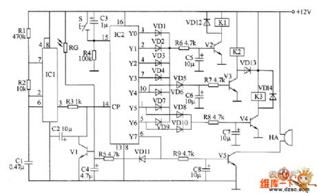
The industrial oil burner controller circuit is composed of the multivibrator, control circuit and fire detection / extinction alarm circuit, and the circuit is shown as the chart. Multivibrator circuit is composed of the time-base integrated circuit IC1, resistors R1, R2 and capacitor C1. Control circuit consists of counting / pulse distributor circuit IC2, reset button S, diodes VD1 ~ VD14, resistors R3 ~ R8, transistors V2 ~ V4, relays K1 ~ K3 and capacitors C3, C5 ~ C7. Fire detection / extinction alarm circuit is composed of the photosensitive resistor RC, transistors V1, V5, resistors R5, R9, capacitors C2, C4, C8 and buzzer HA.
(View)
View full Circuit Diagram | Comments | Reading(3611)
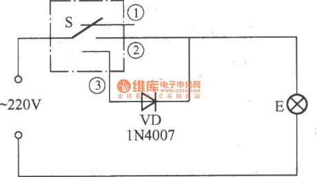
Spark timer circuit diagram
Published:2011/7/21 2:44:00 Author:Ecco | Keyword: Spark timer circuit
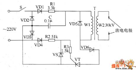
The spark timer circuit is composed of the power switch S, resistors R1 ~ R3, capacitor C, step-up transformer T and the discharge electrode, and the circuit is shown as the chart. When the power switch S is connected and in the positive half cycle of alternating current, the current forms the loop by the VD1, R1, C, VD3, then C starts to charge. In the negative half cycle of AC current, the current forms the loop by VD4, R2, R3, VT and VD2 to make VT be triggered and conduction. R1 selects the 1W metal film resistor, R2 and R3 select 1/4W metal film resistors.
(View)
View full Circuit Diagram | Comments | Reading(1409)
Four-way independent touch switch circuit
Published:2011/5/13 3:54:00 Author:Nicole | Keyword: touch switch
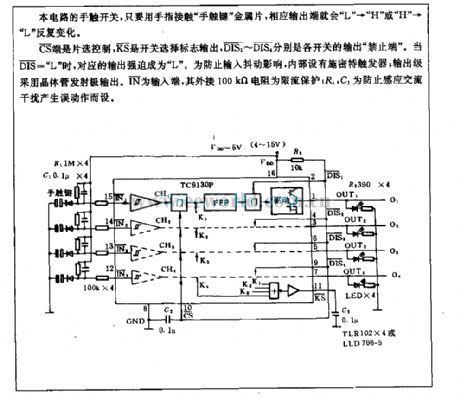
The touch switch of this circuit, if the finger touches the finger touch key metal plate, the output terminal will repeatedly change with L to H or H to L .
CS terminal is chip selection control, KS is switch selection sign output, DIS1~DIS4 are the output prohibition terminal of each switch. When DIS= L , the corresponding output is forced to be L . In order to prevent the input jitter influence, it contains inside Schmidt trigger; the output level adopts transistor emitter to output. IN is input terminal; the external 100kΩ resistance is limit current protection; R1, C1 is used to prevent the induction AC interference. (View)
View full Circuit Diagram | Comments | Reading(1035)
Water tank water level alarm circuit
Published:2011/5/13 3:50:00 Author:Nicole | Keyword: water level, water tank
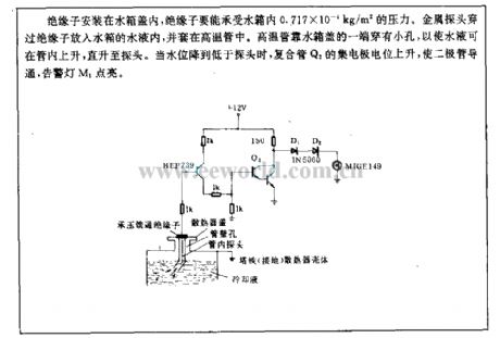
The insulator is fixed in water tank cap, the insulator should bear 0.717*0.001 kg/m2 pressure. The metal detectorpasses the insulator then it is put into water, and it is covered with high temperature tube. One terminal of the high temperature tube which is close to water tank cap has a little hole, it can make the water rise in the tube, even rise to the probe. When the level is lowed than probe, the collector potential of composite pipe Q2 will rise, then the diode turns on, alarm light M1 is lighting. (View)
View full Circuit Diagram | Comments | Reading(797)
Opto-electrical control circuit applied to four-work unite machine
Published:2011/5/13 3:49:00 Author:Nicole | Keyword: opto-electrical control, four-work unite machine
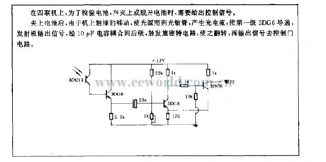
After the battery is clipped, because the movement of touch stick will make the light source shine to photosensitive tube, and produce light current, the first level 3DG6 turns on, the emitter outputs signal, the singal is coupled to back level by 10μF capacitance, Schmitt circuit is triggered and flipped, it outputs singal to control the gate circuit. (View)
View full Circuit Diagram | Comments | Reading(559)
Double relay 100~200W automatical regulator analysis
Published:2011/5/2 7:23:00 Author:Nicole | Keyword: relay, 100~200W automatical regulator
The principles of circuit: the power grid is connected to 3 foot of transformerB by switch, J1's normally closed contact. R1 is sample transistance, the control circuit is composed of BG1, BG2, it can change the control point by adjusting W. When the power grid is lower than 220V, J1 normally closed contact changes the transformer B into boost type. If the output voltage does not exceed 220V, J2 normally closed contact connects to transformer 5 foot. If it is higher than 220V, J2 pulls in and connects to transformer 4 foot. If the power grid is higher than 220V, it controls J1 to pull in by R1 sample, it is connected to transformer 5 foot, then it willform buck type. If output terminal voltage exceeds the set value, then to control J2 pull in by R4 sample, the normally open contact is connected to 4 foot. The selection of components: regulator power depends on the transformer iron core section and enameled wire diameter. The iron chip can use 19×(24~25), the coil adopts 0.27~0.35 high strength enamelled wire to close winding, it should not use packing paper between layers. 1~2 should go around 48 turns, 2~3 should go around 822 turns, from the third foot it uses 0.41~0.51 enamelled wire, 3~4, 4~5 all go around 85 turns. BG1, BG3 chooses 3DG small power tube, BG2, BG4 use PNP silicon middle power tube. There is no special requirements for resistance capacitance. (View)
View full Circuit Diagram | Comments | Reading(541)
Digital display multifunction thermometer circuit
Published:2011/5/13 3:11:00 Author:Nicole | Keyword: Digital display, multifunction thermometer
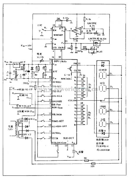
The functions of this circuit are: alarm, display, timing, digital display and temperature display. MM5406 is the part of clock, it is PMOS IC, 40-foot packaging, its functions include: alarm, stop alarming, sleep, 12/24h time selection, second display, fast set h, slow set min, 50/60Hz clock selection.
MM5407 is thermometer used IC, the temperature range is -40~+88℃, the temperature sensor uses LM334 or SL334, the temperature factor is 10mV/℃, it can be adjusted by W4.
This circuit has 9V spare battery. When the AC power is cut off, this battery is used as power supply, then the time clock works normally, but LED will be turned off due to the power failure. (View)
View full Circuit Diagram | Comments | Reading(1034)
Infrared reflecting automatic lamp circuit(TX05D)
Published:2011/7/4 2:48:00 Author:zj | Keyword: Infrared reflecting, automatic lamp
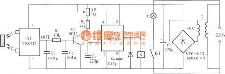
As the diagram shows it is a practical infrared reflecting automatic lamp circuit. When you go closely to it,the lamp lights up.When you leave, the lamp goes out. It can be used for home storage room, bathroom lighting or dresser mirror front lamps and other occasions. (View)
View full Circuit Diagram | Comments | Reading(562)
Infrared remote control lamp switch circuit (2)
Published:2011/7/4 2:52:00 Author:zj | Keyword: Infrared remote control, lamp switch circuit (2)
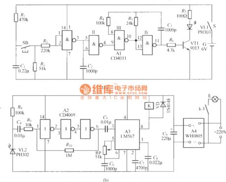
As shown in the figure, circuit (a ) is an infrared light emitter circuit, the oscillation frequency is 20kHz; ( b) is an infrared light receiver circuit and K uses static power consumption memory self-locking relay ( DC5V ZS-01 ). (View)
View full Circuit Diagram | Comments | Reading(1093)
Infrared remote control dimmer lamp circuit
Published:2011/7/4 2:54:00 Author:zj | Keyword: Infrared remote control dimmer lamp circuit
Infrared ray emitter circuit:
Infrared ray receiving controller circuit:
(View)
View full Circuit Diagram | Comments | Reading(748)
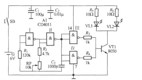
Automatic toilet lamp circuit
Published:2011/7/13 20:36:00 Author:zj | Keyword: Automatic, toilet lamp circuit
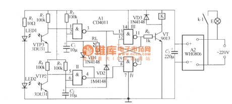
As shown in the figure for the automatic toilet lamp circuit, the lamp lights up when people come in and goes out when people go out. At the same time the circuit also has a light control function. The circuit automatically block at daytime, the lamp doesn't light. LED1, LED2 use PH303 type infrared emitting diode. (View)
View full Circuit Diagram | Comments | Reading(927)
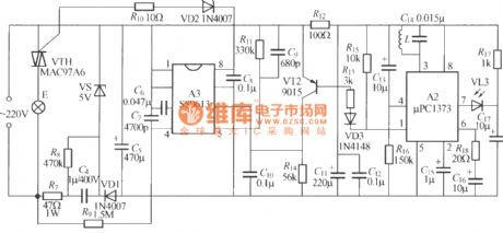
Microwave radar automatic lamp circuit (5)(TX982)
Published:2011/7/4 22:08:00 Author:zj | Keyword: Microwave radar, automatic lamp

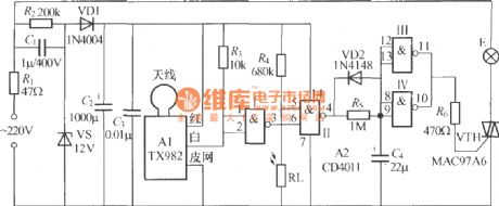
As the diagrams shows it is a automatic lamp with microwave radar TX982. Its feature is that the circuit will not be interfered by its own light and it is vey easy to be installed. It is suitable for washing room,storage room, dresser mirror light etc. It can realize the function that the lamp lights up when people come and it goes out when people leave. (View)
View full Circuit Diagram | Comments | Reading(769)
Microwave radar automatic lamp circuit(3)(TWH9248/9249)
Published:2011/7/4 22:12:00 Author:zj | Keyword: Microwave radar, automatic lamp
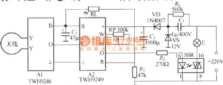
As the diagram shows,it is a automatic lamp which uses TWH9248/TWH9249 microwave emission and receiving sensor made in Guangdong Zhongshan Dahua electronics factory. It has the follow function: When the light at daytime or in room is strong, the lamp will not light up and when it is evening,the lamp will automatically light up.The annular antenna can use Φ3mm enameled wire to bend to Φ150mm circle and to connect to X,Y ports of A1. The circuit needs no debugging, and it can work well. (View)
View full Circuit Diagram | Comments | Reading(907)
Delay light pull switch circuit (2)
Published:2011/7/10 19:58:00 Author:zj | Keyword: Delay light, pull switch circuit
Asthediagramshows it is an improved pull switch delay switch, but the workstability is higher. It has good reliability. (View)
View full Circuit Diagram | Comments | Reading(679)
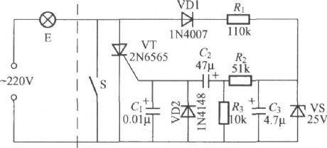
Simple dimmer pull switch circuit
Published:2011/6/30 21:46:00 Author:zj | Keyword: dimmer, pull switch
As the diagram shows itis a simple and practical dimmer pull switch. Just pull the switch when use anditlights.Pull theswitch again andlights darken.Pull again and lights extinguish. It is very convenient. (View)
View full Circuit Diagram | Comments | Reading(664)
Full wave optical control circuit
Published:2011/5/13 2:37:00 Author:Nicole | Keyword: full wave, optical control
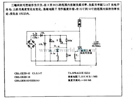
Three terminal TRIAC is used as switch, it controls the load power in the range of 0~90%, the load power changes with the brightness of L14T photoelectric switch Q1. Thermal resistor T is used as temperature compensation, it keeps power constant in the range of 25℃~50℃, the change is within 3%. (View)
View full Circuit Diagram | Comments | Reading(630)
Body induction alarm circuit
Published:2011/5/12 22:31:00 Author:Nicole | Keyword: body induction, alram
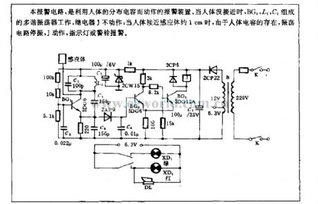
This alarm circuit uses the body distributed capacitance to make a alarm device. When there is nobody closing, BG1, L1, C1 form a multivibrator, relay J is not working; when people are closing the inductor about 1cm, because of the body capacitance, the oscillation circuit will stop vibrating, J starts to work, then the indicator light or warning bellwill alarm. (View)
View full Circuit Diagram | Comments | Reading(1018)
| Pages:197/312 At 20181182183184185186187188189190191192193194195196197198199200Under 20 |
Circuit Categories
power supply circuit
Amplifier Circuit
Basic Circuit
LED and Light Circuit
Sensor Circuit
Signal Processing
Electrical Equipment Circuit
Control Circuit
Remote Control Circuit
A/D-D/A Converter Circuit
Audio Circuit
Measuring and Test Circuit
Communication Circuit
Computer-Related Circuit
555 Circuit
Automotive Circuit
Repairing Circuit