
Index 184
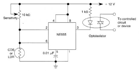
PORCH_LIGHT_CONTROL
Published:2009/6/17 2:33:00 Author:May

This circuit can control the on/off cycle of a light via a CDS photocell, and turn it off after a pre-set period. The light can only be turned on when CDS cell is in darkness, and it stays on for a time determined by the 555 circuit. On time depends on RI and C1 and is about 80 seconds with the values shown. (View)
View full Circuit Diagram | Comments | Reading(1128)
DARK_ACTIVATED_RELAY_WITH_HYSTERESIS
Published:2009/6/17 2:32:00 Author:May
The hysteresis of a 555lC can be used to advantage for sensing a drop in light. An LDR or CDS cell with about 2 to 8 k resistance at desired light level should be used. (View)
View full Circuit Diagram | Comments | Reading(1346)
OUTDOOR_LIGHT_CONTROLLER
Published:2009/6/17 2:31:00 Author:May
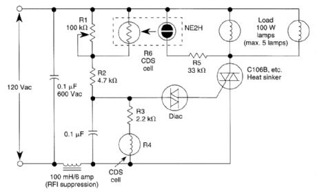
A neon bulb and a CdS photocell enclosed in a light-tight enclosure forrn an optocoupler. A diac/triac combination is used to provide the snap-switch effect. A second CdS photocell acts as the main sensor.
As darkness approaches, the resistance of R4 begins to increase. At a threshold level, the diac triggers the triac and causes the neon bulb to light. This reduces the resistance of R6, causing the diac to trigger the triac, which lights the neon bulb and provides power to the load.As moming light comes up, the process is reversed. The neon bulb goes out and the SCR turns off. (View)
View full Circuit Diagram | Comments | Reading(1600)
COMBINED_LIGHT__DARK_ACTIVATED_SWITCH
Published:2009/6/17 2:30:00 Author:May
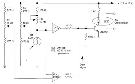
Two op arnps used in a bridge circuit configuration detect high and low light levels. Potentiometer R2 sets the dark level and R1 controls the light level. R3 is set so that about 1/2 the supply voltage appears across R4 at the desired light level. R1 and R2 set the trip point of the optoisolator IC2 at darker or lighter ambient levels, as required. (View)
View full Circuit Diagram | Comments | Reading(1102)
PRECISION_DARK_ACTIVATED_SWITCH_WITH_HYSTERESIS
Published:2009/6/17 2:29:00 Author:May
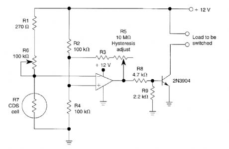
A CdS cellis one leg of a bridge circuit Potentiometer R6 In another leg sets the trip point Potentiometer R5 provides hysteresis adjustment to prevent “chattering” or hunting of the relay Thelight level has to increase noticeably before the 2N3904 turns off and the circuit deactivates. (View)
View full Circuit Diagram | Comments | Reading(731)
CARRIER_CURRENT_BABY_ALERT_TRANSMITTER
Published:2009/6/17 2:24:00 Author:May
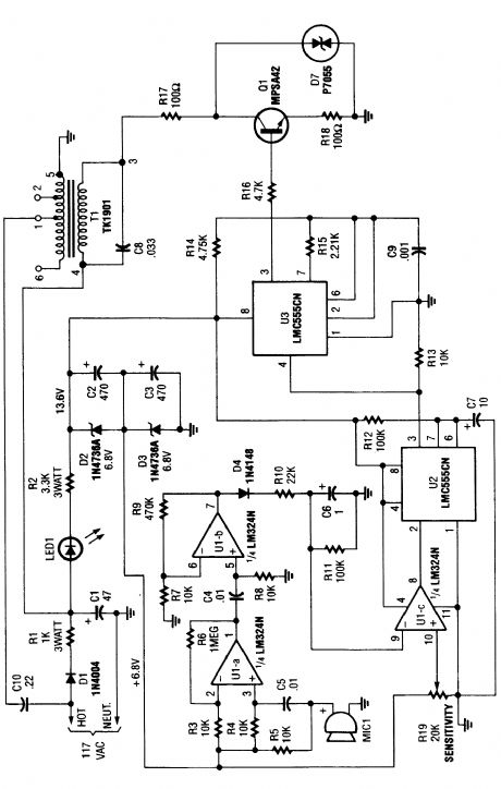
The baby-alert transmitter is built around an LM334 quad op amp(U1), two LMC555CM CMOS oscillator/timers(U2 and U3), and a few support components. The transmitter sends a signal on receipt of a sound at MIC1. It has a frequency of around 125 kHz and can be used to trigger an alarm receiver. (View)
View full Circuit Diagram | Comments | Reading(3016)
SIMPLE_LIGHT_ACTIVATED_ALARM
Published:2009/6/17 2:23:00 Author:May
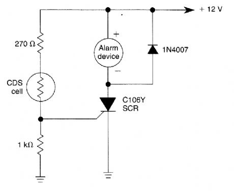
A cadmium-sulfide photocell conducts when a light beam strikes it. This triggers the SCR and activates the alarm device. (View)
View full Circuit Diagram | Comments | Reading(881)
HALOGEN_LAMP_PROTECTOR
Published:2009/6/17 2:17:00 Author:May
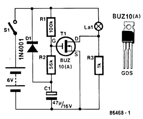
This circuit produces a soft turn-on for halogen lamp filaments upon powerlng up,MOSFETRI used is a BUZ10, which has 0.2Ω RDS on.R1,R2,and C1 set the turn-on rate and D1 discharges C1 at turn-off. (View)
View full Circuit Diagram | Comments | Reading(1072)
SENSITIVE_TRIAC_CONTROLLER
Published:2009/6/17 2:17:00 Author:May
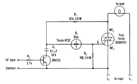
The single transistor connected between the capacitor and the common side of the ac line allows a Iogic-level signal to control this triac power circuit. Resistor R2 prevents false triggering of the triac by the trickle current through the diac. (View)
View full Circuit Diagram | Comments | Reading(2771)
CMOS_TOUCH_DIMMER
Published:2009/6/17 2:13:00 Author:May
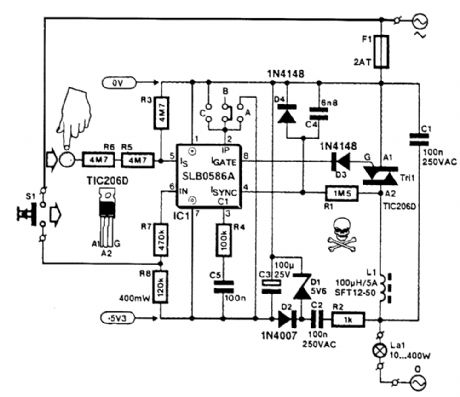
A Seimens SLB0586A IC allows the construction of a simple touch-controlled dimmer circuit.The circuit controls a triac ac switch,which allows control of loads from 10 to 400 W. (View)
View full Circuit Diagram | Comments | Reading(3306)
SIMPLE_TRIAC_CIRCUIT
Published:2009/6/17 2:08:00 Author:May
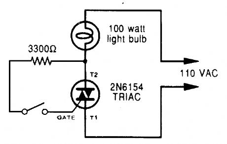
A triac can be used as a lirte-operated ac power switch that can directly control lamps, heaters, or motors. A brief and small current pulse into the gate turns the triac on; it remains on until the main current reverses. (View)
View full Circuit Diagram | Comments | Reading(1333)
PHASE_CONTROLLED_DIMMER
Published:2009/6/17 2:05:00 Author:May
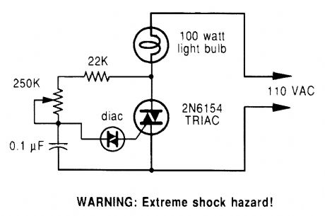
A phase-controlled dimmer delays the triac VAC tum-on to a selected point in each successive ac half cycle. Use this circuit only for incandescent lamps, heaters, soldering irons, or “universal” motors that have brushes. (View)
View full Circuit Diagram | Comments | Reading(3)
THREE_POWER_LEVEL_TRIAC_CONTROLLER
Published:2009/6/17 2:04:00 Author:May
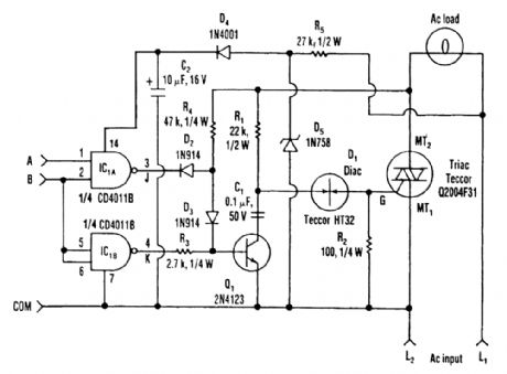
Three power levels are supplied by the two logic inputs of this enhanced circuit. R5, D4, D5, and C2 form a power supply for the logic IC. They can be omitted if another source of low voltage is available. (View)
View full Circuit Diagram | Comments | Reading(767)
AUTOMATIC_PORCH_LIGHT_CONTROL
Published:2009/6/17 2:01:00 Author:May
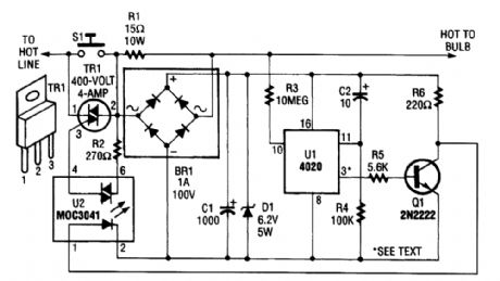
The automatic porch-light control circuit holds a triac on until a 4020 divider counts a number of 60-Hz powerline pulses. The circuit turns off a light after a predetermined time by using pins other than pin 3 of UI. Various times can be set. Consult the 4020 data sheet for information. (View)
View full Circuit Diagram | Comments | Reading(3541)
HOLIDAY_LIGHT_SEQUENCER
Published:2009/6/17 1:59:00 Author:May
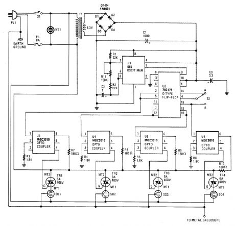
Integrated circuit UI (a 555 oscillator/timer) is wired as a conventional pulse generator. The fre-quency of the pulse generator is controlled by potentiometer R11. Resistor R2 puts a reasonable limit on the highest speed attainable.The output of the pulse generator is fed to the common clock input of U2, a 74C175 quad D-type flip-flop. Each flip-flop is configured so that its Q output is coupled to the D input of the subsequent flip-flop.Information on the D input of each flip-flop is transferred to the Q (and Q) outputs on the lead-ing edge of each clock pulse. Switch 52 allows you to invert the information on the D input of the first flip-flop at any time during the cycle. This allows you to create a number of different sequences, which are determined by the state of the CQ output at the time of the switching.Some of the possible sequences are:· 1 through 4 on, 1 through 4 off;· 1 of 4 on sequence;· 1 of 4 off sequence;· 2 of 4 on sequence;· 1 and 3 on to 2 and 4 off;· and other instances when the sequence of events is difficult to determine.However, if 52 is switched to position B while all outputs are high or all are low (which seldom occurs), the sequence stops and the outputs remain either all on or all off. If that happens, you only need to switch back to position A for at least one pulse duration, then back to position B again.Likewise, S2 should be in position A (pin 4 connected to pin 14) each time the power is turned on. This is because the data on pin 4 must be a logic 1 in order to start a sequence; otherwise all out-puts remain at logic 0, regardless of the clock pulses.Each output of the sequencing circuit is connected to an MOC3010 optoisolator/coupler (U3 through U6), which contains an infrared-emitting diode with an infrared-sensitive diac (triac driver or trigger) in close proximity. The diac triggers the triac, which carries the 117-volts ac.Each time that the infrared-emitting diode receives a logic 1, it turns on and causes the diac to conduct. With the o(Itoisolator/coup ler's internal diac conducting, the triac turns on, and power is supplied to whatever load is plugged into the corresponding ac socket. So, the sequencing circuit and the 117-V ac outputs are optically coupled and are effectively isolated from each other.Power for the sequencing circuit is provided by a 6.3-V miniature transformer. The output of the transformer is rectified by a four-diode bridge circuit, the output of which is filtered by C1 (1000-pF electrolytic capacitor). Capacitor C3 is added at the supply pin of U2 to suppress transients. (View)
View full Circuit Diagram | Comments | Reading(1827)
RELAY_FUSE_FOR_BATTERY_CHARGES
Published:2009/6/17 1:53:00 Author:May
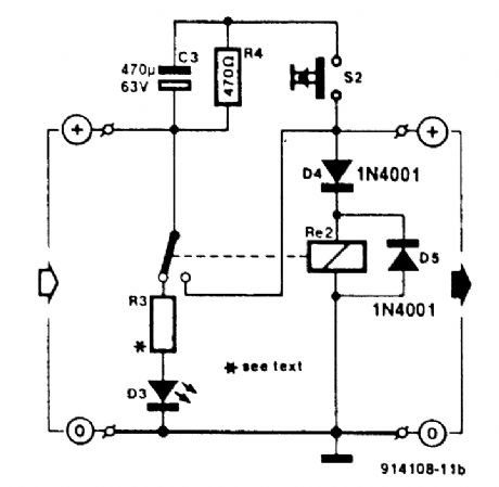
Charged capacitor C3 and momentary push-button switch S2 are used to momentarily energize relay RE2. The batte:y under charge energizes the relay to hold it closed. S2 will energize the relay even if the battery is too far discharged initially to energize it. (View)
View full Circuit Diagram | Comments | Reading(917)
BATTERY_WATCHDOG
Published:2009/6/17 1:42:00 Author:May
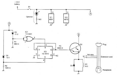
This circuit uses a pair of Zener diodes to monitor battery voltage of a 12-V battery. If below 11 V, D1 ceases to conduct, pin 3 of IC2 goes high, setting FF IC2 turning on Q1, K1, and the battery charger. At excess of 14-V battery voltage (full charge), D2 conducts, resetting FF IC2, and cutting off the battery charger. (View)
View full Circuit Diagram | Comments | Reading(786)
Flash_Signal_Alarm
Published:2009/6/17 0:32:00 Author:May
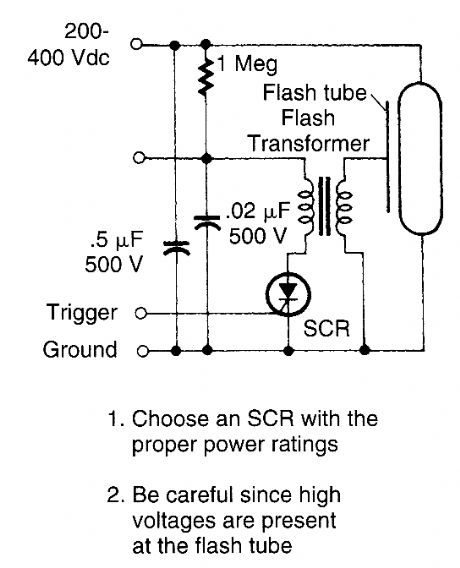
This circuit is useful if you need a low-energy flashing alarm. The 200 to 400-dc supply should have enough internal resistance to charge the 0.5 μF capacitor between flashes, about 2 or 3 time constants, which means about 500 kΩ to 1 MΩ for a 1-s rate. Use lower values for higher rates. (View)
View full Circuit Diagram | Comments | Reading(765)
PULSED_INFRARED_TRANSMITTER_FOR_ON_OFF_CONTROL
Published:2009/6/16 22:21:00 Author:May
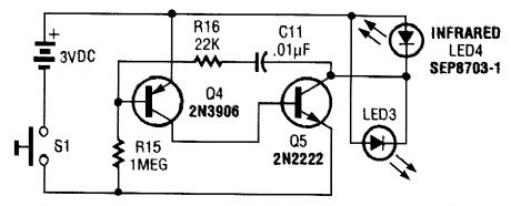
This transmitter consists of an oscillator and LEDs. It generates a pulsed tone of around 850 Hz. (View)
View full Circuit Diagram | Comments | Reading(673)
IR_CONTROLLED_REMOTE_A_B_SWITCH
Published:2009/6/16 22:11:00 Author:May
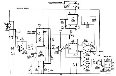
Useful for A/B control, the IR receiver shown controls a relay from an infrared beam that has a pulsed tone-modulated signal. Q1 is the photo receptor feeding op amp IC1, tone decoder IC2, and flip-flop IC3. IC5 turns off the indicator LEDs after about 15 seconds. (View)
View full Circuit Diagram | Comments | Reading(1178)
| Pages:184/312 At 20181182183184185186187188189190191192193194195196197198199200Under 20 |
Circuit Categories
power supply circuit
Amplifier Circuit
Basic Circuit
LED and Light Circuit
Sensor Circuit
Signal Processing
Electrical Equipment Circuit
Control Circuit
Remote Control Circuit
A/D-D/A Converter Circuit
Audio Circuit
Measuring and Test Circuit
Communication Circuit
Computer-Related Circuit
555 Circuit
Automotive Circuit
Repairing Circuit