
Index 201
Starting Circuit By Using FET
Published:2011/7/17 9:46:00 Author:Robert | Keyword: Starting, FET
The picture shows the starting circuit by using FET. (View)
View full Circuit Diagram | Comments | Reading(586)
Battery Protection Circuit
Published:2011/7/16 10:03:00 Author:Robert | Keyword: Battery, Protection
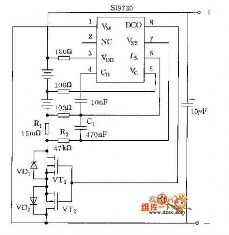
The picture shows the battery protection circuit. (View)
View full Circuit Diagram | Comments | Reading(824)
Practical Under-Voltage And Over-Voltage Protection Circuit
Published:2011/7/17 8:01:00 Author:Robert | Keyword: Practical, Under-Voltage, Over-Voltage, Protection
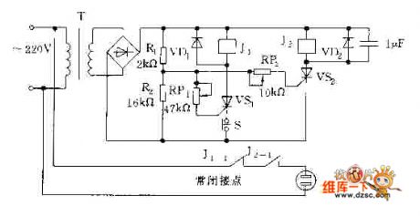
The picture shows the practical under-voltage and over-voltage protection circuit. (View)
View full Circuit Diagram | Comments | Reading(2490)
Power Over-Voltage Protection Circuit By Using μPC3423
Published:2011/7/17 8:18:00 Author:Robert | Keyword: Power, Over-Voltage, Protection
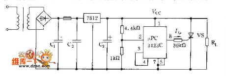
The picture shows the power over-voltage protection circuit by using μPC3423. (View)
View full Circuit Diagram | Comments | Reading(630)
Electronic Switch And Driving Circuit
Published:2011/7/17 8:14:00 Author:Robert | Keyword: Electronic, Switch, Driving
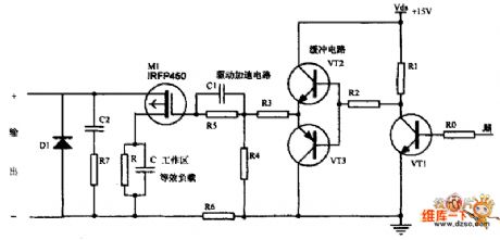
The picture shows the electronic switch and driving circuit. (View)
View full Circuit Diagram | Comments | Reading(650)
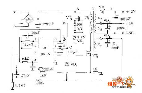
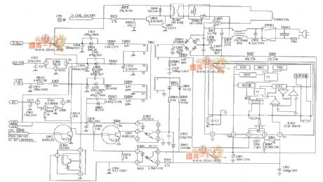
LG CF-25H84 color TV power supply circuit diagram
Published:2011/7/17 0:58:00 Author:nelly | Keyword: LG, color TV, power supply
View full Circuit Diagram | Comments | Reading(8529)
MCl45028 general Infrared, ultrasonic or RF remote control receiving decoder circuit
Published:2011/7/15 21:41:00 Author:Christina | Keyword: general, Infrared, ultrasonic, RF, remote control, receiving decoder
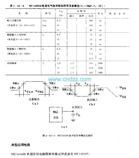
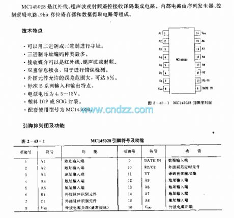
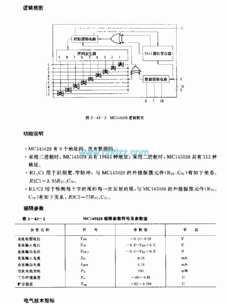
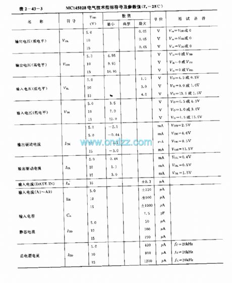
The MCl45028 is designed as one kind of general red-needle line, ultrasonic or RF remote control receiving decoder circuit. The internal circuit is composed of the sequence generator, the logic control circuit, the 9-bit shift register, the data extraction circuit.etc.
Features
It uses the binary or ternary to find the address;The ternary addressing coding has the maximum species;The receive media can be the infrared, ultrasonic in the error detection;The permissible error range of the external components can be 5%;Standard B series input and output characteristics;The power voltage is 4.5-18V;Plastic DIP or SOG package;The matching model is MCl145026.
(View)
View full Circuit Diagram | Comments | Reading(548)
MCl45436 general infrared remote control receiving circuit (dual-tone multi-frequency signal receiving circuit)
Published:2011/7/15 21:57:00 Author:Christina | Keyword: general, infrared, remote control, receiving circuit, dual-tone, multi-frequency, signal receiving
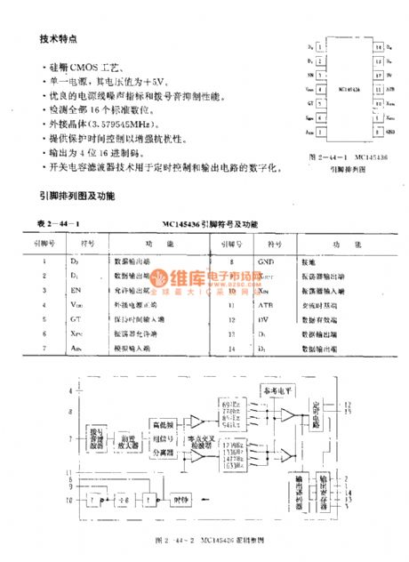
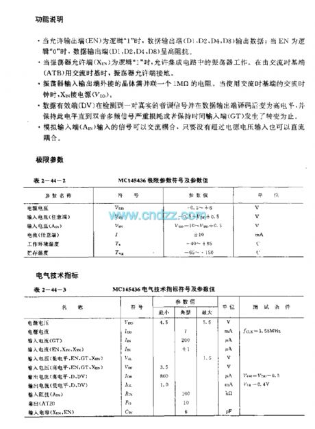
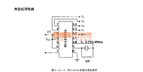
The MC14536 is designed as one kind of dual-tone multi-frequency signal receiving circuit that can be used in telephones, and it can be used in the multi-functional general infrared remote control signal receiver. The internal circuit is composed of the dial tone filter, the preamplifier, the high and low frequency group signal separator, the zero-crossing wave detector, the band-pass filter, the amplitude detector, the output decoder and the reference clock oscillator.etc.
Features
The Silicon gate CMOS process;The single power supply with the voltage of +5V;Good power supply line noise index and dial tone performance;It tests all the 16 standard digitals;External crystal (3.579545 MHz);It provides protection time to enhance the immunity performance;It outputs the 4-bit hexadecimal code;The switch capacitance filter technology can be used in the digitization of the timing control and output circuit.
(View)
View full Circuit Diagram | Comments | Reading(1179)
Medical treat ventilator controller
Published:2011/7/1 1:21:00 Author:Nicole | Keyword: ventilator, controller
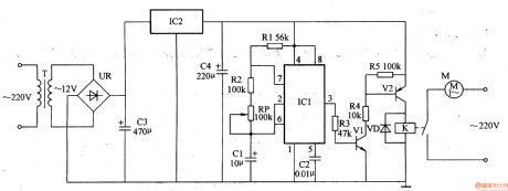
The medical treat ventilator controller circuit is composed of astable oscillator, control circuit and power supply circuit, it is shown in the figure 9-155.
The astable oscillator circuit is made of resistors R1, R2, potentiometer RP, capacitors C1, C2 and time base integrated circuit IC1.
The control circuit consists of resistors R3-R5, transistors V1, V2, diode VD and relay K.
The power supply circuit is composed of power transformer T, bridge rectifier UR rectifier, filter capacitors C3, C4 and there terminals steady voltage integrated circuit IC2.
(View)
View full Circuit Diagram | Comments | Reading(2840)
Motor protector 16
Published:2011/6/27 22:10:00 Author:Nicole | Keyword: Motor, protector
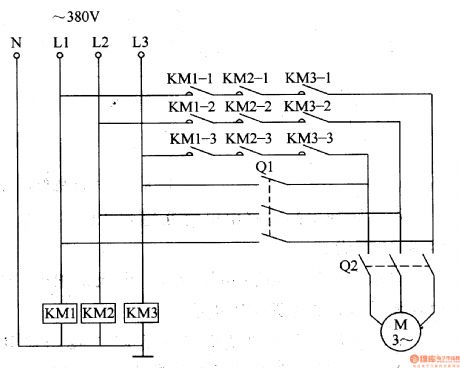
This motor protector circuit is made of AC contactor KM1, it is shown in the figure 8-52.
When 380V AC power voltage is normal, the AC contacts are all turned on, if knife switch Q2 is closed, then motor M runs.
Due to lightning or other reasons, the 380V AC voltage is lack-phase, one of KM1-KM3 AC contacts will not pull in or power failure and release, the motor M's power supply cirucit is cut off, then it protects the motor M. For example, when L2 phase line voltage disappears, AC contact KM2 releases, the normally open contact KM2-1-KM2-3 turns off.
(View)
View full Circuit Diagram | Comments | Reading(608)
Motor protector 15
Published:2011/6/27 21:53:00 Author:Nicole | Keyword: Motor, protector
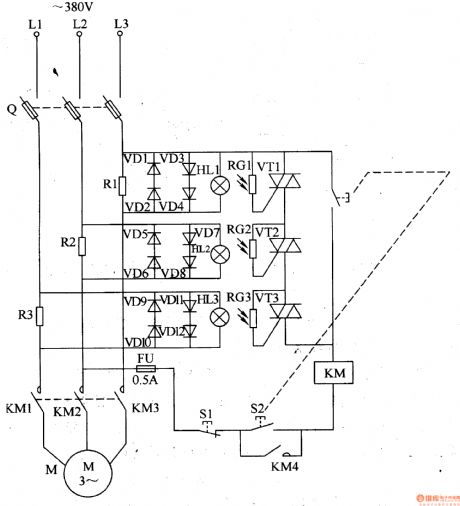
This motor protector circuit is current sampling detection circuit and optical control protection circuit, it is shown in the figure 8-51.
The current sampling detection circuit is made of sampling resistors R1-R3.
The optical control protection circuit consists of protection diodes VD1-VD12, small bulbs HL1-HL3, photosensitive resistors RG1-RG3 and thyristors VT1-VT3.
Q is fuse type knife switch, FU is fuse, S1 is stop button, S2 is starter button, KM is AC contactor.
When starter button S2 is pressed, KM pulls in, the normally open contact is turned on, motor M starts running, when the three-phase AC supply is normal, the both sides of sampling resistors R1-R3's voltage all drop to 1V.
(View)
View full Circuit Diagram | Comments | Reading(586)
The control circuit diagram of optical coupler electrical heating
Published:2011/5/9 21:25:00 Author:Ecco | Keyword: control circuit, optical coupler , electrical heating
The pulse output from pulse oscillator reachesthe positive electrode of the light-emitted diode in the solid by LED. The luminous intensity of LEDis changed with pulse duty factor. Then the breakover degree of photo-thyristor is changed to realize the purpose of constant temperature control.
The pulse oscillator is composed of trigger circuit and constant temperature control circuit of solid relay. The pulse oscillator in the circuitry is a type of oscillator with steady frequency and adjustable pulse duty factor. To regulate the charging and discharging time of convertibility capacitance C1 by changing RP, then the pulse duty factor is changed. While needing to raise heat temperature, the RP can be turned right in the chart to relay the charging time of C1; Or the RP can be turned left may decrease the discharging time of C1. The period of surge in the circuitry is 1255, and account for the range of O. 4%~99. 6% in adjustable pulse duty factor. (View)
View full Circuit Diagram | Comments | Reading(596)
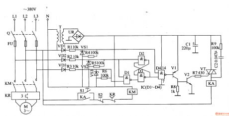
Zero-voltage motor open-phase protection circuit diagram
Published:2011/5/17 3:31:00 Author:Ecco | Keyword: Zero-voltage, motor, protection circuit, open-phase

Figure 141 shows the Zero-voltage motor open-phase protection circuit diagram. When running motor occurs single-phase outage, the protection device can automatically cut off power to avoid motor occuring open-phase running. Working principle: when normal operation, the potential of the three-phase power balance point E is zero.
(View)
View full Circuit Diagram | Comments | Reading(1702)
Infrared sensing automatic door control circuit diagram with KC778B
Published:2011/5/17 3:16:00 Author:Ecco | Keyword: Infrared sensing , automatic door , control circuit
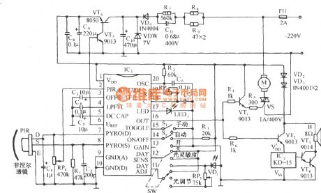
The circuit is shown as the chart. It is a control circuit which composed of infrared specific integrated circuit KC778B and KC778B is the center of the circuit. It’s surrounded by a pyroelectric infrared sensor head PIR, light control and light control adjustment circuit, a three-state select control, automatic restart function and manual control block status sensing functions and so on. (View)
View full Circuit Diagram | Comments | Reading(4172)
Motor protector 14
Published:2011/6/27 21:39:00 Author:Nicole | Keyword: Motor, protector
This motor protector circuit is composed of power supply circuit and phase failure detection protection circuit, it is shown in the figure 8-50.
The power supply circuit is made of power transformer T, rectifier diode VD3, fliter capacitor C2, current limiting resistor R4 and LED VL.
The phase failure detection protection circuit consists of resistors R1-R3, capacitor C1, diodes VD1, VD2, potentiometer RP, transistors V1, V2 and relay K.
The phase failure protection circuit's sensitivity can be changed by adjusting RP.
(View)
View full Circuit Diagram | Comments | Reading(801)
Motor protector 13
Published:2011/6/27 21:29:00 Author:Nicole | Keyword: Motor, protector

This motor protector circuit is composed of power supply circuit, phase sequence detection circuit, trigger and protection control circuit, it is shown in the figure 8-49.
The phase sequence detection circuit is made of diodes VDl-VD3, resistors R1-R6 and steady voltage diodes VS1-VS3.
The protection control circuit consists of transistors V1, V2, resistors R7-R9, capacitor C2, thyristor VT and middle relay KA.
The motor control circuit is composed of starter button S1, stop button S2, knife switch Q, fuse FU, heat relay KR and AC contactor KM.
(View)
View full Circuit Diagram | Comments | Reading(866)
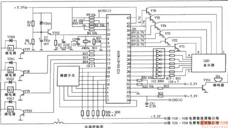
Amproluck MB-23 PC grill microwave computer control panel
Published:2011/5/12 2:18:00 Author:Ecco | Keyword: Amproluck , PC, grill , microwave , computer , control panel
View full Circuit Diagram | Comments | Reading(753)
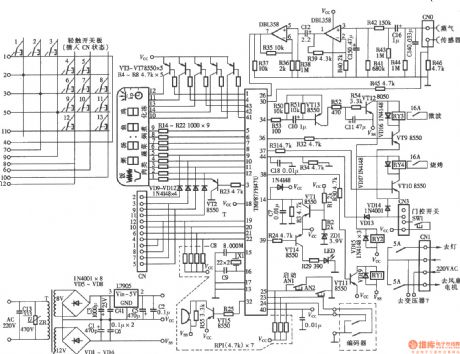
Amproluck WD850ES PC microwave computer control panel
Published:2011/5/12 2:17:00 Author:Ecco | Keyword: Amproluck, PC , microwave , computer , control panel
View full Circuit Diagram | Comments | Reading(761)
Simple light-operated street lamp circuit diagram(6)
Published:2011/6/28 2:35:00 Author:Ecco | Keyword: Simple , light-operated , street lamp

The chart shows the simple light-operated street lamp circuit with better performance , and it can be used in the automatic control of street lamps in residential district. The controlled street light can use incandescent bulbs or energy-saving fluorescent lamps.
(View)
View full Circuit Diagram | Comments | Reading(1594)
Switching circuit diagram with photocoupler
Published:2011/5/13 4:16:00 Author:Ecco | Keyword: Switching circuit, photocoupler
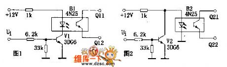
According to the figure 1, when the input signal ui is in low level, the transistor V1 is placed in a closed state, the current of LED in photocoupler B1 is nearly 0, the resistance between Q11 and Q12 is so high to result in the switch be off ; When the ui is in high level, the LED of Bi is lit, the resistance between Q11 and Q12 becomes low,the switchis switch on . As Ui is in low level, switch is impassable, the circuitry is in high level conducting state. In the same argument, in the figure 2, because of having no semaphore(Ui for low level), switch turns on, the circuitry is in low level conducting state.
(View)
View full Circuit Diagram | Comments | Reading(696)
| Pages:201/312 At 20201202203204205206207208209210211212213214215216217218219220Under 20 |
Circuit Categories
power supply circuit
Amplifier Circuit
Basic Circuit
LED and Light Circuit
Sensor Circuit
Signal Processing
Electrical Equipment Circuit
Control Circuit
Remote Control Circuit
A/D-D/A Converter Circuit
Audio Circuit
Measuring and Test Circuit
Communication Circuit
Computer-Related Circuit
555 Circuit
Automotive Circuit
Repairing Circuit