
Index 203
motor headlight auto-changing controller circuit(I)
Published:2011/7/12 0:40:00 Author:chopper | Keyword: motor, headlight, auto-changing controller,
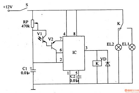
Principle of the circuit The motor headlight auto-changing controller circuit consists of light control circuit and control implementation circuit, which is shown in figure 7-1.
Light control circuit is formed by the photosensitive transistor Vl,transistor V2,potentiometer RP,capacitors Cl and C2 and the time-base integrated circuit IC. Control implementation circuit is formed by 3 feet inner circuit of IC, relay K and diode VD. (View)
View full Circuit Diagram | Comments | Reading(758)
agricultural non-tower pressure-charged water feeder(1)
Published:2011/7/13 21:29:00 Author:chopper | Keyword: agricultural, non-tower, pressure-charged, water feeder
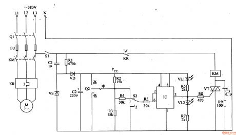
Rural water supply system adopts the non-tower pressure-charged water supply device, and drawback of this water control device is that the control contact of electric connecting pressure gauge is easy to ablate,thus thepressure will get out of control.This example describes the agricultural non-tower pressure-charged water feeder,and the control circuit adopts l2V DC voltage power supply, and the current through control contact of electric connecting pressure gauge is small,thus can avoid the control contact erosion.The circuit is stable and reliable,and production costs is low. The principle of circuit This agricultural non-tower pressure-charged water feeder circuit is formed by the power circuit and the detection control circuit,which is shown in figure 4-152.
(View)
View full Circuit Diagram | Comments | Reading(916)
Subtraction Circuit of Two Operational Amplifiers Input from Inphase End
Published:2011/7/11 2:18:00 Author:Joyce | Keyword: Subtraction, Operational Amplifiers, Inphase End
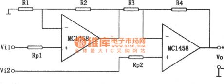
As shown in the figure is a subtraction circuit of two operational amplifiers input from inphase end. According to the circuit analysis, the relationship between input and output is as follows:
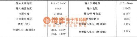
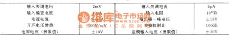
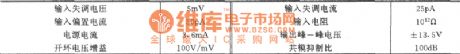
The typical values of main parameters of series 1458/1558: (View)
View full Circuit Diagram | Comments | Reading(632)
The FSK circuit composed of ME564
Published:2011/7/14 5:29:00 Author:Borg | Keyword: FSK circuit
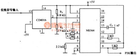
This is the FSK circuit which is composed of ME564. In the circuit, NE564 is a simulating PLL integrated circuit, the FSK modulation is done by CD4016 analog switch which is controlled by dual-state signals. CD4016 makes the 2-pin of NE564 in the voltage of 5V and 1.42V, i.e 5Vx[R2/(R1十R2)]=1.42V. The bias current of the power supply phase detector is controlled by the voltage on 2-pin. Therefore, when the phase is continuous, the output of the VCO can be changed. The capacitor C0 which determines the central frequency of VCO does not change, the drift between FSK frequencies can be adjusted by R1 and R2.
(View)
View full Circuit Diagram | Comments | Reading(2499)
The FSK modulation circuit composed of 74LS74
Published:2011/7/14 5:57:00 Author:Borg | Keyword: FSK modulation
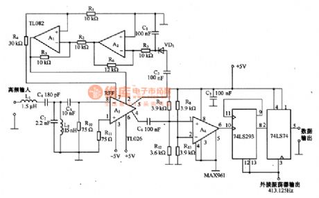
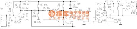
This is the FSK modulation circuit composed of 74LS74. The FSK modulation circuit has neither PLL nor bandpass filter with high Q value, so there is no need of any tune adjustment in the high-frequency modulation circuit. The 2 tune circuits composed of L1, L2, C4 and C7 is working as the input filter, which only allows the frequency band with central frequency of 10MHZ to pass, and the high frequency difference amplifier A3 can amplify the 10MHZ signal. The auto gain control (AGC) circuit is composed of A1 and A2. The HF signal, which is magnified by A3, can be switched into digital signal by comparator A4.
(View)
View full Circuit Diagram | Comments | Reading(3511)
instrument-panel lamp dimmer
Published:2011/7/12 22:29:00 Author:chopper | Keyword: instrument-panel lamp, dimmer
Drivers may feel very harsh at the moment the instrument-panel lamp is open at night.This example describes the instrument-panel lamp dimmer,which can reduce the visual impact of the drives,thereby it can enhance the safety of night driving. The principle of circuitThe instrument-panel lamp dimmer circuit is formed by the voltage regulator circuit,reset circuit,square-wave oscillator,protection circuit and electronic switching circuit,which is shown in figure 7-35. Regulator circuit consists of resistorsR1 and the voltage regulator diode VS. Reset circuit consists of capacitor C1, resistors R3, R4.
(View)
View full Circuit Diagram | Comments | Reading(728)
timing controller(2)
Published:2011/7/13 22:02:00 Author:chopper | Keyword: timing controller

The timing controller described in this example is of functions like time display,cycle timing, single timing,and manual function,and the regular timing time is 1-90min.It can be used to control a variety of electrical equipments which should work at regular time or work intermittently. The principle of circuit The timing controller circuit is formed by the power supply circuit, the clock signal generator,counting distributor,RS trigger and the switch output circuit, which is shown in figure 4-165.
(View)
View full Circuit Diagram | Comments | Reading(707)
Improved Inphase Parallel Subtraction Circuit
Published:2011/7/11 2:24:00 Author:Joyce | Keyword: Improved , Inphase, Parallel , Subtraction
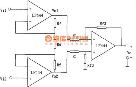
As shown in the figure is an improved inphase parallel subtraction circuit.
The circuit is not only characteristic of high input resistance, but also overcomes inconveniences caused by Vo which is floating output .Typical values of main parameters of LF444 :
(View)
View full Circuit Diagram | Comments | Reading(664)
Gain Linearity Adjustable Subtraction Circuit
Published:2011/7/11 2:12:00 Author:Joyce | Keyword: Gain, Linearity Adjustable , Subtraction
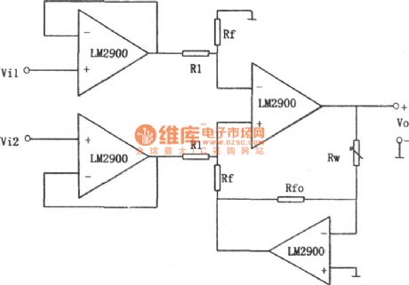
As shown in the figure is a gainlinearity adjustable subtraction circuit.
We can draw from circuit analysis :
Changing the value of Rw can adjust that of the gain, which presents a linear change.
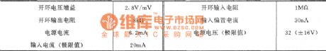
Because the input end of this circuit uses two op-amps as voltage follower, input resistance can be increased greatly. The circuit chooses LM2900 (similar products like CF2900 / CF3900, LM3900) as its component. This series of devices is monolithic integrated current differential four operational amplifier, which is usually referred to as “NORTON amplifier. Its characteristic is that it has a wide range of the power supply, both single and dual powers are feasible, and the output is protected by short circuit.The typical values of the main parameters of LM2900 is as follows:
(View)
View full Circuit Diagram | Comments | Reading(739)
Inphase Parallel Subtraction Circuit
Published:2011/7/11 1:56:00 Author:Joyce | Keyword: Inphase , Parallel , Subtraction
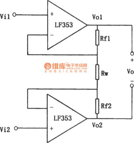
As shown in the figure is an inphase parallel subtraction circuit. The relationship between input and output is shown as follows:
The most obvious characteristic of the circuit is that it has a high input resistance. When the value of Rf1, Rf2 is not 0, changing the value of Rw can adjust the gain quite easily (but it is nonlinear). The external circuit does not need matched resistance. Its defect is that Vo is floating output, which would be inconvenient in some circumstances.
Typical values of the main parameters of LF353: (View)
View full Circuit Diagram | Comments | Reading(671)
Single Power Low Voltage Bandpass Filter Circuit
Published:2011/7/11 2:42:00 Author:Joyce | Keyword: Single Power, Low Voltage, Bandpass , Filter
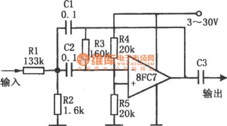

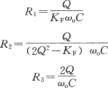
As shown in the figure is a single power low voltage bandpass filter circuit. The circuit uses a single power amplifier 8FC7 to constitute a second-order band-pass filter. Its power supply voltage ranges from 3 V to 30 V. When deciding the value of its component, one needs to identify the center frequency f0 of the band-pass filter, then chooses a suitable capacitance C (C = C1 = C2) according to the following table. After that one should determine the value of Q. which represents a parameter of characteristics of frequency selection. If the value of Q is high, bandpass will be narrow. When Q is 10, one will get a response frequency of - 40 dB every octave. But if the value of Q is too large, the circuit will not be stable. The values of R1, R2, and R3 can be calculated based on the following 3 formulas.
(View)
View full Circuit Diagram | Comments | Reading(695)
Subtraction Circuit
Published:2011/7/11 2:44:00 Author:Joyce | Keyword: Subtraction
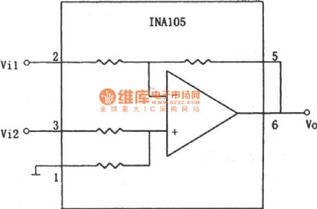
As shown in the figure is a subtraction circuit (1)composed of other components.The relationship of input and output of the circuit is :Vo=10(Vi2-Vi1) (View)
View full Circuit Diagram | Comments | Reading(725)
Active Narrowband Filter Circuit
Published:2011/7/11 3:01:00 Author:Joyce | Keyword: Active , Narrowband , Filter
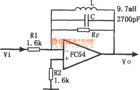

The filter uses LC as feedback impedance of the operational amplifier. The circuit is simple and convenient to debug, and it has the good frequency-selecting performance. Signal gain of the circuit is ZF/R1,and the frequency of the maximum gain point is decided by LC , the amount of which being :
The feedback impedance maximizes and is approximate to RF on the resonance point of LC, so at that time, the circuit has the largest gain. But, it will be influenced by the quality factor of no-load of inductance coil. (View)
View full Circuit Diagram | Comments | Reading(735)
Very Low Frequency Active Filter Circuit
Published:2011/7/11 3:18:00 Author:Joyce | Keyword: Very Low Frequency , Active , Filter
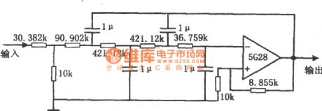
As shown in the figure is a vlf active filter circuit. This is a Butterworth four-order active low-pass filter, which can be used to filter the interference voltage caused by the noise of vlf random pulses on the dc level signal. Its cut-off frequency (-3 dB) is about 8 Hz.When the frequency is 18 Hz, the gain will drop to 20 dB. Natural attenuation within the pass-band is 0.467. And the input resistance is about 40 k Ω. The resistance network of the filter is connected in parallel by several precision resistances with metal film. If the precision of 1μF capacitance reaches a certain amount , the cut-off frequency fc will be close to the theoretical value. (View)
View full Circuit Diagram | Comments | Reading(1094)
Automatic Sprinkling Irrigation Controller (8)
Published:2011/7/11 6:31:00 Author:Sue | Keyword: Automatic, Sprinkling Irrigation, Controller
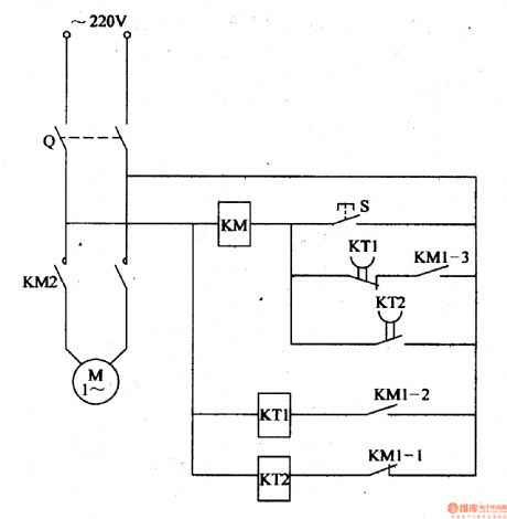
When the power switch Q is on, time relay K will form a circuit by ac contactor KM's normally closed contact KM1-1 and K begins to work. When it reaches Km's given delay time, KT2's time-delay closed normally closed contact will be connected which will make KM connected. KM's normally open main control contact KM2 and two groups of normally open assistant contact KM1-2,KM1-3 will be connected. The water pump electric motor M will begin to work and begin to sprinkle. At the same time, KM's normally closed contact KM1-1 is disconnected which will make Km disconnected. Its normally open contact is disconnected. But because KM's normally open contact KM1-3 has been connected, KM coil remains connected by KT1's time-delay disconnected normally closed contact and KM1-3. M will keep working. (View)
View full Circuit Diagram | Comments | Reading(580)
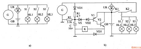
Automatic Sprinkling Irrigation Controller (6)
Published:2011/7/11 5:58:00 Author:Sue | Keyword: Automatic, Sprinkling Irrigation, Controller
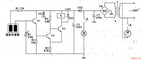
The 220v voltage will generate direct current 6v voltage on the filter capacitor C2 after it is reduced by T. One circuit of the voltage will provide the mini water pump's direct current electric motorwith working voltage(see the dotted line in the figure, the ac electric motor's large and medium water pumps use 220v ac voltage as working power); The other circuit will generate +5.6v voltage which will be provided to V1-V3 and the relay K after it is reduced by VD2, stablized by VS, filtrated by C1.
When the humidity sensor is sticked into the soil, it can detect the soil's humidity. When the soil humidity is high, the resistance value between the humidity sensor's two electrodes is small which will make V1,V2 connected. V3 is disconnected and the relay K is not connected. The water pump motor M doesn't work. When the soil humidity is becoming low, the resistance value between the humidity sensor's two electrode will become higher. When it reaches a certain value, V1 and V2 will be disconnected. V3 is connected and the relay K will be connected. Its normally open contact will be connected which will make the water pump motor M begins to work and the equipment of sprinkler irrigation will begin to work. (View)
View full Circuit Diagram | Comments | Reading(1337)
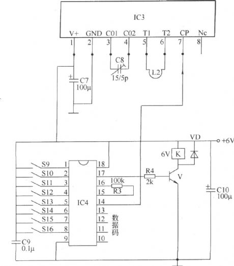
wireless remote control switch circuit(two)
Published:2011/7/12 7:14:00 Author:Lena | Keyword: wireless, remote control, switch
Here introduces a 4-way wireless remote control switch which adopts wireless remote control transmitting/receiving and wireless remote control coding/decoding integrated circuit, and the switch can control four kinds of different appliance or control different work states of the one applianceat one time.This wireless remote control switch circuit consists of wireless remote control transmitting circuit and wireless remote control receiving circuit, as shown in the figure.The wireless remote control transmitting circuit consists of wireless remote control transmitting head IC1, wireless remote control coder and switch control circuit.
(View)
View full Circuit Diagram | Comments | Reading(1318)
multipurpose wireless remote control switch circuit
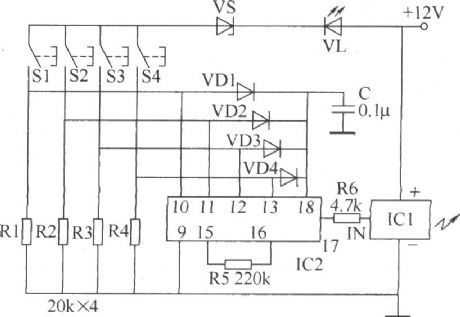
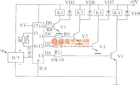
Published:2011/7/12 3:38:00 Author:Lena | Keyword: multipurpose, wireless, remote control, switch
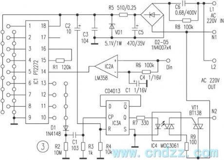
This remote control switch uses wireless code/encode mode, which is not limited by aeolotropy, the beeline control distant is ≤100m.The switch can control electric appliance cut/off whose power is at about 400W.It consists of remote controller and receiving circuit. The remote controller has a small bulk and beautiful shape, and can be hung on a bunch of keys that is convenient to carry-on. The switch has four keystokes which can transmit 4-way control signal respectively.
Figure 1 is a remote control emitter circuit.IC1 is a low power loss code transmitting chip using CMOS technology.
(View)
View full Circuit Diagram | Comments | Reading(1443)
Over-Voltage Protection Circuit Composed Of MC3X164 Series
Published:2011/7/13 8:01:00 Author:Robert | Keyword: Over-Voltage, Protection
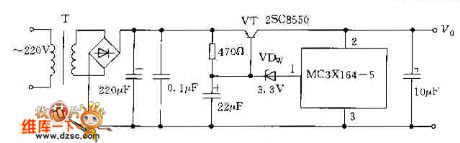
The picture shows the over-voltage protection circuit composed of MC3X164 series. (View)
View full Circuit Diagram | Comments | Reading(655)
wireless remote control switch circuit(six)
Published:2011/7/12 7:12:00 Author:Lena | Keyword: wireless, remote control, switch
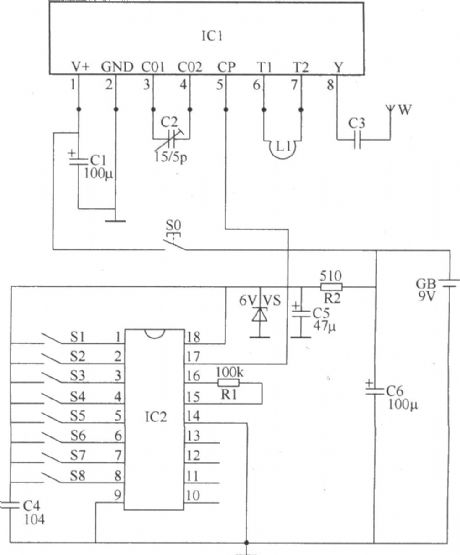
The wireless remote control switch introduced in the text has these features: great emitter power, high sensitivity, low manufacture cost, the max remote control distance can reach 500m. The switch can be used as control switch of lamps and household appliance, and the switch can also be used to control electric toys.
This wireless remote control switch circuit consists of wireless remote control transmitting circuit and wireless remote control receiving circuit two parts.
The wireless remote control transmitting circuit shown in the figure consists of data/encrypted code integrated circuit IC2, wireless remote control transmitting integrated circuit IC1, resistor R1,R2, capacitor C1-C6, steady pressure diode VS, control button S0, coding switch S1-S8, oscillator coil L and antenna W.
(View)
View full Circuit Diagram | Comments | Reading(1626)
| Pages:203/312 At 20201202203204205206207208209210211212213214215216217218219220Under 20 |
Circuit Categories
power supply circuit
Amplifier Circuit
Basic Circuit
LED and Light Circuit
Sensor Circuit
Signal Processing
Electrical Equipment Circuit
Control Circuit
Remote Control Circuit
A/D-D/A Converter Circuit
Audio Circuit
Measuring and Test Circuit
Communication Circuit
Computer-Related Circuit
555 Circuit
Automotive Circuit
Repairing Circuit