
Index 215
Illumination Controller (9)
Published:2011/7/6 0:37:00 Author:Sue | Keyword: Illumination, Controller
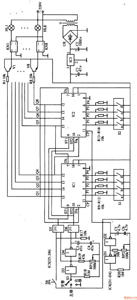
When the terminal outputs high level, the corresponding KN makes the illumination circuit connected. When the terminal outputs low level, KN makes the illumination circuit disconnected. For example, when Q1 terminal outputs high level, V1 is connected which will make KN1 connected. The first circuit of illuminations will be illuminated. When Q1 terminal becomes low level. V1 is disconnected and KN1 is disconnected. HL1 are off.Q1-Q8 keep changing the states under the control of the clock pulse. Then HL1-HL8 will be controlled to show various illumination effects.
S1 and S2 are used to set the initial state of the bidirectional shift register. Then push S4, write the set parameter to the shift register. If S1 is connected and P1 terminal outputs high level, IC's Q1 terminal will output high level.
S3 changes the shift register's shift directions by controlling the low-frequency multivibrator. Put 53 to ALTERNATION , the low-frequency multivibrator will begin to work. (View)
View full Circuit Diagram | Comments | Reading(642)
Illumination Controller (8)
Published:2011/7/6 5:41:00 Author:Sue | Keyword: Illumination, Controller
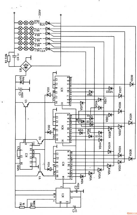
The 220v ac voltage will provide IC1,IC2 and V1-V3 with 9V working voltage after it is reduced by C4, rectificated by UR, stablized by VS, filtrated by C.
After IC2 is connected and reset, its Y0 terminal(pin 3) will output high level which will make V1 connected. IC3 will be connected and begins to work. At the same time, the oscillator also begins to work. Then IC1's pin 3 will output oscillate signals which will serve as the count pulse of IC3-IC5.
After IC3 begins to count, its Y1 terminal will output high level. VD4 is connected which will make VT1 connected. The first circuit of illuminations HL1 will be illuminated.
When IC3's Y2 terminal outputs high level, Y1 terminal returns to low level. VD8 is connected which will make VT2 connected. The second circuit of illuminations HL2 are illuminated while HL1 are off. (View)
View full Circuit Diagram | Comments | Reading(614)
Illumination Controller (7)
Published:2011/7/6 0:26:00 Author:Sue | Keyword: Illumination, Controller
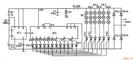
The 220v ac voltage will generate 9V voltage after it is rectificated by VD13-VD16, reduced by R3, stablized by VS, filtrated by C3. The voltage will provide IC1 and IC2 with working voltage.
After the multivibrator begins to work, IC1's pin 3 will output oscillate signals which will serve as IC2's count pulse. Then IC2 begins to count and Y0-Y9 will output high level in turn.
When IC2's Y0 terminal(pin 3) outputs high level, its high level will be put on VT1's gate electrode through VD1 which will make VT1 connected. The first circuit of illuminations HL1 are illuminated.
When Y1 terminal outputs high level, Y0 terminal has low level again. VD2 is connected which will make VT2 connected. The second circuit of illuminations HU are illuminatedwhile HL1 are off. (View)
View full Circuit Diagram | Comments | Reading(608)
Illumination Controller (6)
Published:2011/7/6 0:20:00 Author:Sue | Keyword: Illumination, Controller
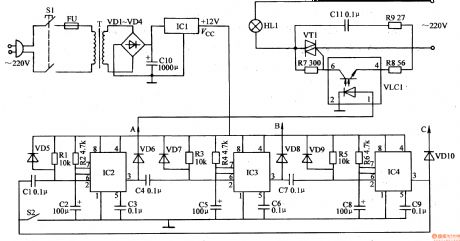
When the power switch S1 is connected, the 220v ac voltage will provide the univibrator circuit with working voltage afterit is reduced by T, rectificated by VD1-VD4, filtrated by C10, stablized by IC1.
S2 is the trigger switch. When S2 is pushed, IC2's pin 2 will output a negative pulse,which will make the univibrator composed of IC2 reverse. IC2's pin 3 will output high level, which will make the optical coupler VLC1's inner LED illuminated. The optical transistor is connected which will make bidirectional triode thyristor VT1 connected. The first group of illuminations HL1are illuminated. (View)
View full Circuit Diagram | Comments | Reading(657)
Illumination Controller (5)
Published:2011/7/6 0:10:00 Author:Sue | Keyword: Illumination, Controller
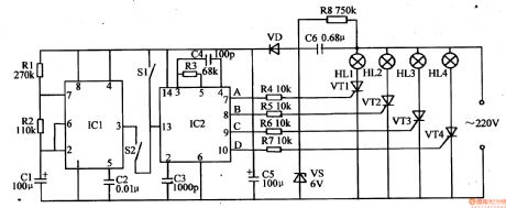
When the power is on, the 220v ac voltage will generate about 6V direct current voltage after it is reduced by C6,stablized by VS,rectificated by VD, filtrated by C5. The voltage will provide IC1 and IC2 with working voltage.
When S1 is pushed, IC2's pin 13 will input a high level pulse. IC2 will be altered to the other illumination mode automatically. When IC2's pin 7-10 output high level, the controlled thyristors VT1-VWwill beilluminated. When IC2's pin 7 outputs high level, VT1 is connected and the first circuit of illuminations HL1are illuminated. When IC2's pin 8 outputs high level, Vm is connected and the second circuit of illuminations HL2are illuminated. When IC2's pin 10 outputs high level, VT4 is connected and the 4th circuit of illuminations HL4are illuminated. (View)
View full Circuit Diagram | Comments | Reading(607)
Illumination Controller (10)
Published:2011/7/6 0:43:00 Author:Sue | Keyword: Illumination, Controller
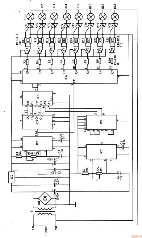
When the power is on, the 220v ac voltage will provide IC1-IC6 with +5v direct current working voltage after it is reduced by T, rectificated by UR, filtrated by C1 and C2, stablized by ICO.
After the multivibrator A begins to work, IC1's pin 3 will output low-frequency oscillate signals. One serves as IC3's count pulse. The other serves as IC6's shift clock pulse.
After IC3 begins to work, the count pulse signals will be counted and frequency-divided. Its pin 12, pin 9, pin 8, pin 11 will output count pulse's 2nd,4th,8th,16th frequency-divided signals respectively. (View)
View full Circuit Diagram | Comments | Reading(606)
Illumination Controller (4)
Published:2011/7/6 0:11:00 Author:Sue | Keyword: Illumination, Controller
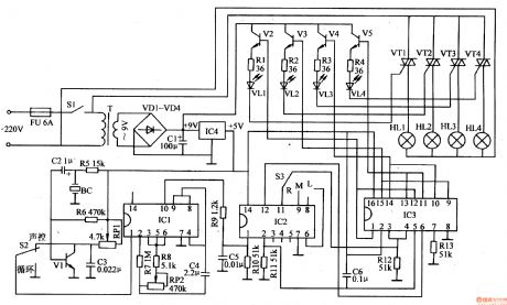
When the power switch S1 is connected, the ac 220v voltage will provide V2-V5 with 9V direct current working voltage after it is reduced by T,rectificated by VD1-VD4, filtrated by C1. The other circuit will provide the voice-operated circuit, oscillator and controller with +5v voltage after it is stablized by rC4. After the oscillator works, IC1's pin10 will outputoscillatepulse signals which will serve as IC2's control pulse. IC3 will output pulse control voltage under the control of IC2. Then the illuminations will be on and off as VT1-VW is connected and disconnected under the control of V2-V5. (View)
View full Circuit Diagram | Comments | Reading(910)
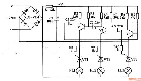
Illumination Controller (11)
Published:2011/7/5 6:29:00 Author:Sue | Keyword: Illumination, Controller
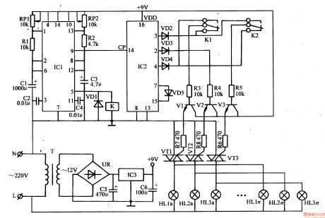
After the clock oscillator begins to work, IC1's pin 9 will output low-frequency oscillate signals as IC2's count pulse. Then IC2 begins to count and Y0-Y3 will output high level one by one which will make V1-V3 and VT1-VT3 connected in turn. Then the 3rd illuminations are illuminated in turn.
The circuit is a low-frequency oscillator. After it begins to work, IC1's pin 5 will output low-frequency pulse signals. When IC1's pin 5 outputs positive pulse, K is connected and K1's,K2's normally open contactors are connected while normally closed contactors are disconnected. When IC1's pin 5 outputs negative pulse, K is released. K1's and K2's nomally closed contactors are connected and nomally open contactors are disconnected. (View)
View full Circuit Diagram | Comments | Reading(562)
Illumination Controller (3)
Published:2011/7/5 23:45:00 Author:Sue | Keyword: Illumination, Controller
When the working power is on, the thyristor V3 is the first to be connected(because V3's base bias resistance value is lower than V1's and V2's), its collector becomes low level. Because capacitor C4's voltage can't realise abrupt change, and V2's base voltage is close to 0V, V2 is disconnected. V2's collector has high level. The thyristor VT2 is connected and the 2nd circuit of illuminations HL2 are illuminated. V2's collector's high level makes V1 connected through C3. V1's collector has low level and VT1,VT3 are disconnected. The 1st circuit of illuminations HL1 and the 3rd circuit of illuminations HL3 are not illuminated. (View)
View full Circuit Diagram | Comments | Reading(531)
Non-Volatile Memory Integrated Circuit Diagram
Published:2011/7/7 8:37:00 Author:Vicky | Keyword: Non-Volatile, Memory Integrated Circuit
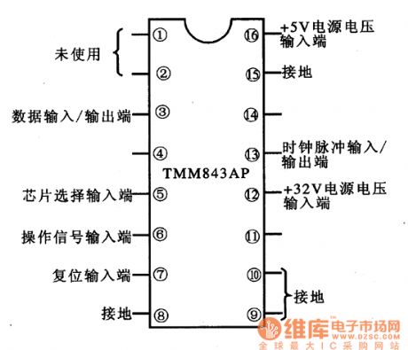
Picture 1: Ranking of IC TMM8432AP pin
TMM843AP is a non-volatile memory integrated circuit produced by Toshiba Corporation. It is widely used in control system of color television , DVD player, audio device, and air-conditioner, mainly for saving information and program.
1 functions and features
Internal part of IC TMM843AP is mainly composed of data storage UO interface circuit, chip selection circuit, reset control circuit, time base circuit, operating signal processing circuit and some other auxiliary functional circuits.
2 function and data of pins
IC TMM8431P uses 16 pins which are in dual-in-line package. The ranking of the pins are as shown in picture 1.
Note: If the memory function does not work, check whether the power supply voltage of + 32V in the pin 12 works regularly or not first. (View)
View full Circuit Diagram | Comments | Reading(948)
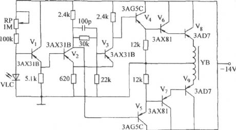
LCD Backlight Luminance Auto-control Circuit (Visible Light Luminance Sensor LX1970) Diagram
Published:2011/7/7 8:36:00 Author:Vicky | Keyword: LCD Backlight, Luminance Auto-control Circuit , Visible Light Luminance Sensor
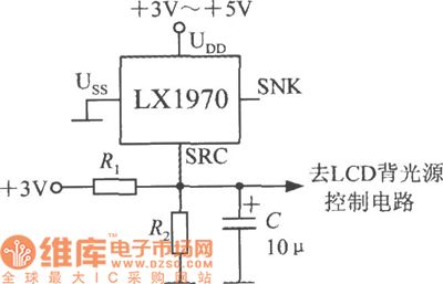
When it turns dark, LX1970 will automatically start up the LDC backlight to make white LED luminous. Luminance auto-control circuit is shown in the picture. The maximum and minimum value of the luminance can be controlled and set by resistances R1 and R2. The responding time and leaching of disturbance of 50Hz power grid can be adjusted by changing the capacity of capacitance C. LX1970 adopts +3.3 to +5V power supply. When only SRC end is used, the SNK end should hang in air. Suppose that the white LED is driven by 0.25~1.25V output voltage, then 0.25V is the minimum luminance value of LED while 1.25 is the maximum value. (View)
View full Circuit Diagram | Comments | Reading(978)
SPT1141/1151 multi-function switch controller typical application circuit
Published:2011/7/6 21:54:00 Author:Christina | Keyword: multi-function, switch controller, typical application
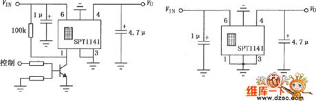
Figure: SPT1141/1151 multi-function switch controller typical application circuit
(View)
View full Circuit Diagram | Comments | Reading(577)
The timing alarm circuit composed of 5G26
Published:2011/7/7 21:04:00 Author:Seven | Keyword: timing alarm
In the figure is the timing alarm circuit composed of integrated computing amplifier 5G26 and the NAND. The left part of the circuit is a timing device, 5G26 composes the comparing amplifier circuit, VT1 and R1 compose a constant current source, which charges C1, and the LEV of Vc is rising gradually (non-inverting phase input of the integrated op-amp), the RP potentiometer adjusts the voltage on the inverting input terminal, by comparing the non-inverting or inverting input LEV, RP decides whether to output a high or low LEV. The right part and NAND are as the voltage control.
(View)
View full Circuit Diagram | Comments | Reading(584)
Single-chip microcomputer fryer control circuit
Published:2011/7/7 2:00:00 Author:Christina | Keyword: Single-chip microcomputer, fryer, control circuit
The Single-chip microcomputer fryer control circuit is as showni in the figure:
(View)
View full Circuit Diagram | Comments | Reading(693)
The simple fade out/in switch circuit
Published:2011/7/7 20:54:00 Author:Seven | Keyword: fade out/in
The simple fade out/in switch circuit is shown in the figure, usually, the switch S is open, triodes VT1 and VT2 are both blocked, the lamp E is not glowing. When we need the lamp to light, just close S, the 220V AC current is turned into an impulse DC current after rectification, the capacitor C is charged by switch S and resistor R, which makes the voltage on C rise. Therefore, VT1 can acquire rising basic bias current through R2, so VT1 and VT2 are both turn into the amplifying state from the blocked, finally, they are fully conducted.
(View)
View full Circuit Diagram | Comments | Reading(1825)
The light control electric switch circuit
Published:2011/7/7 20:32:00 Author:Seven | Keyword: light control, electric switch
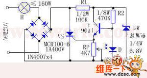
The ON and OFF of the light control electric switch is completed by the conduction or block of SCR, and SCR is under control of the brightness of the natural light (or man-made light). This device is fit for the street, the dorm corridor and other public places, which can make lamps light at daytime and put out at night, so the power is saved. Working principle: see as the figure, the 220V AC is past the bulb and rectified in full bridge, after that, it becomes a DC impulse voltage as the forward bias voltage.
(View)
View full Circuit Diagram | Comments | Reading(645)
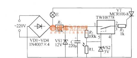
Light control street lamp circuit using TWH8778 (2)
Published:2011/7/7 22:23:00 Author:zj | Keyword: Light control, street lamp circuit, using TWH8778
View full Circuit Diagram | Comments | Reading(640)
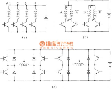
The step motor drive circuit and its drawing
Published:2011/7/7 7:50:00 Author:Seven | Keyword: step motor, drive circuit
View full Circuit Diagram | Comments | Reading(650)
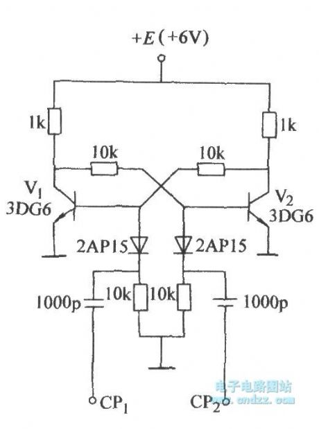
The transformative emitter coupling dual steady circuit
Published:2011/7/7 7:52:00 Author:Seven | Keyword: transformative emitter, dual steady circuit
View full Circuit Diagram | Comments | Reading(606)
The double steady circuit without reversed bias
Published:2011/7/7 7:54:00 Author:Seven | Keyword: double steady circuit, reversed bias
View full Circuit Diagram | Comments | Reading(649)
| Pages:215/312 At 20201202203204205206207208209210211212213214215216217218219220Under 20 |
Circuit Categories
power supply circuit
Amplifier Circuit
Basic Circuit
LED and Light Circuit
Sensor Circuit
Signal Processing
Electrical Equipment Circuit
Control Circuit
Remote Control Circuit
A/D-D/A Converter Circuit
Audio Circuit
Measuring and Test Circuit
Communication Circuit
Computer-Related Circuit
555 Circuit
Automotive Circuit
Repairing Circuit