
Index 218
Pendant Light Controller (3)
Published:2011/7/5 22:06:00 Author:Sue | Keyword: Pendant, Light Controller
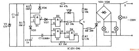
When S is connected, the 220v voltage will be put on the 3rd group of illuminations EL3 through S which will make EL3 illuminated. The other circuit will generate +12v voltage after it is rectificated by VD1-VD4, current-limited and voltage-reducted by M, filtrated by C1, stablized by VS. Apart from providing IC with working power, the +12v voltage will charge C2 through R2 and VD5.
When the +12v voltage is generated, because C2's voltage can't realise abrupt change, NOT gate D1's input terminals(IC's pin1 and pin2) have low level. Its output terminal(IC's pin 3)'s high level will charge C3 through VD7 which will make NOT gate D2's and D3's output terminal (IC's pin 4 and pin 10) have low level. V and VT are not connected. The first group of illuminations EL1 and the second group of illuminations EL2 are not illuminated. (View)
View full Circuit Diagram | Comments | Reading(745)
Pendant Light Controller (2)
Published:2011/7/5 23:17:00 Author:Sue | Keyword: Pendant Light, Controller
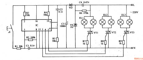
When S is pushed continuously, IC's pin 1 will input positive pulse signals continuously. Its output terminals(pin 6,pin 5,pin 4, pin 3) will output signals inbinary order of 0001-1000(0 is low level and 1 is high level). IC's pin3, pin 4 ,pin 5 are connected to VT3, Vm, VT1 respectively by R9, R8, R7. When one of IC's output terminals outputs high level, the controlled thyristor will be connected.That is when IC's pin 3 outputs high level, VT3 is connected and the 3rd circuit of illuminations EL3 are illuminated. When IC'spin 4 outputs high level, Vm is connected and the 2nd circuit of illuminations EU are illuminated. When IC's pin 5 outputs high level, VT1 is connected and the first circuit of illuminations EL1 are connected. (View)
View full Circuit Diagram | Comments | Reading(626)
MSP430F149 alarm circuit
Published:2011/7/4 0:35:00 Author:John
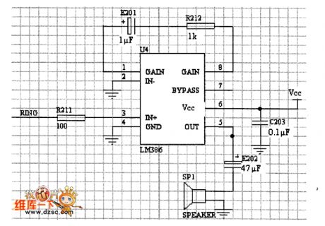
The main part of the circuit is to drive a buzzer. Once one end is grounded to the buzzer, the other end is connecting with the chip to take effects. Taking the drive capability of MSP430F149 into account, an amplifier is needed. The picture shows the implementation of the alarm circuit.
It can be seen through the figure that acquisition circuit is simple and practical.To reduce the effects from the power supply’s input ripple, a 0.1μF capacitor is added to the pin feet of the power supply for filtering.
(View)
View full Circuit Diagram | Comments | Reading(630)
Light-Operated Streetlight (14)
Published:2011/7/5 23:24:00 Author:Sue | Keyword: Light-Operated, Streetlight
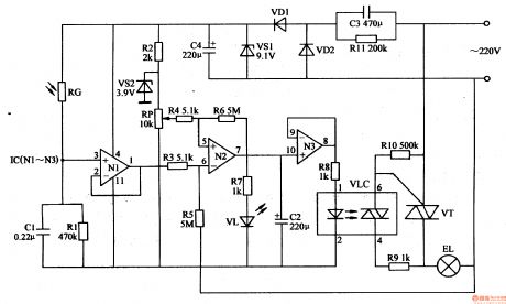
In the daytime, when there is strong light, RG has a low resistance value because of the light. N1 will output high level(about 8v) because its positive phase input terminal has a higher voltage than its negative phase input terminal. N2 and N3 both output low level. VLC's inside LED is not illuminated and the light-operated thyristors are not connected. VT is disconnected and EL is not illuminated.
In the evening, RG has a high resistance value because of lack of light, which will make N1 output low level(lower than 1v). N2 and N3 both output high level which will make VLC and VT begin to work. EL is illuminated.
When RP's resistance value is adjusted, EL can be illuminated when it is dark and can be off when daytime comes. (View)
View full Circuit Diagram | Comments | Reading(1511)
The precious domestic appliance burglarproof alarm
Published:2011/7/6 20:45:00 Author:qqtang | Keyword: domestic appliance, burglarproof alarm
This precious domestic appliance burglarproof alarm is different from other alarms, it is installed in the householde appliance shell. In the shell, on the one hand, there is the battery as the working power supply, on other other hand, the low voltage power supply in the shell is taken as the standby power supply. When the appliance is stolen, the power supply of the alarm is connected, and it is starting to work and make signals which are sent to the owner. As the alarm can self-lock after the emitter is power-on, so it will be in working state all the time, and it will send the alarm signal continuously.
(View)
View full Circuit Diagram | Comments | Reading(626)
The 40-line medical use wireless calling system circuit
Published:2011/7/6 21:33:00 Author:qqtang | Keyword: medical use, wireless calling system

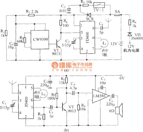
In figure 1 is one of the encoding emitter circuits, the system is equipped with 40 emitter circuit. In figure 2 is the reception display circuit. We divide the 40 codes into 4 teams, i.e 0, 1, 2 and 3 (only team 0 and 1 have drawn in figure 2). For the 10 codes 00~09 in team 0, all the address pins of the decoding circuit are suspended, when the receiver gets signals from an emitter of team 0, the signals are decoded by IC1 and encoded by IC5, and the corresponding indicator in LED00~LED09 are lit as memory.
(View)
View full Circuit Diagram | Comments | Reading(684)
The application circuit of 5-function remote control PT8A977/978
Published:2011/7/6 21:19:00 Author:qqtang | Keyword: application circuit, remote control
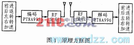
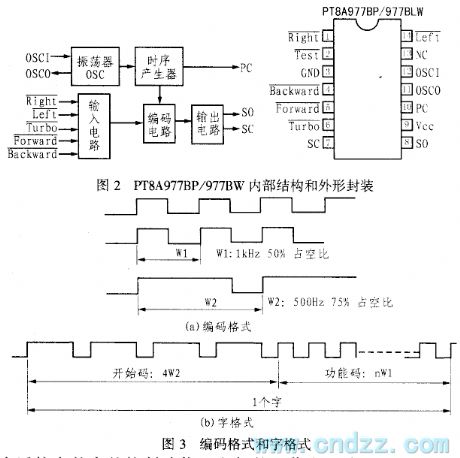
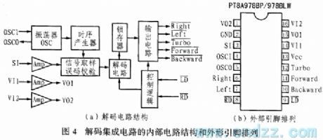
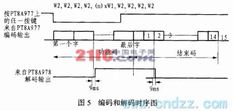
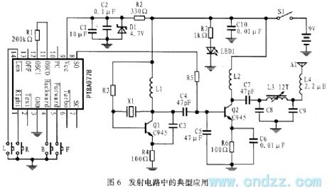
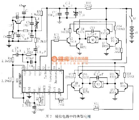
The remote toy car adopts the servo motor wireless remote control technology. The basic requirements of remote circuit design are good function, low cost, smooth operation, flexible control, simple wire, effective anti-disturbance, etc. Usually, the drive of the remote toy car needs 2 micro DC servo motors to complete the functions of heading forward, backing up, turning left, turning right and acceleration, etc. The toy car market is full of competition, so requirements on the electric function of them are higher and higher.
(View)
View full Circuit Diagram | Comments | Reading(3289)
The 6v,0.6w alarm flashing lamp circuit
Published:2011/7/6 21:01:00 Author:qqtang | Keyword: alarm flashing lamp
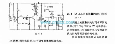
The 6v,0.6w alarm flashing lamp circuit(see as figure 26.4) The alarm lamps in traffic have different powers, whose working voltage can be provided by the 6V battery, such a lower voltage can be switched into the high voltage that the flash lamps need. The figured charge voltage can be regulated by the potentiometer R6, and the transistor peak value current can be regulated by potentiometer R3. (View)
View full Circuit Diagram | Comments | Reading(679)
The improved car steering alarm integrated application circuit of LZ1041
Published:2011/7/6 20:48:00 Author:qqtang | Keyword: steering alarm, application circuit
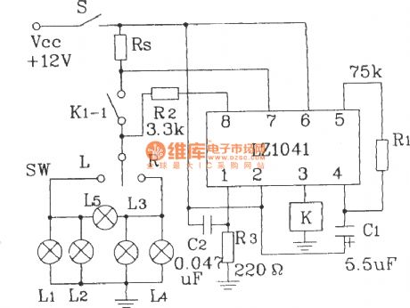
The improved car steering alarm integrated application circuit of LZ1041 (View)
View full Circuit Diagram | Comments | Reading(607)
The thyristor broken phase protection circuit
Published:2011/7/6 0:55:00 Author:Borg | Keyword: thyristor, broken phase, protection
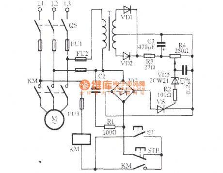
View full Circuit Diagram | Comments | Reading(745)
The modular burglar alarm system
Published:2011/7/6 0:55:00 Author:Borg | Keyword: modular burglar alarm
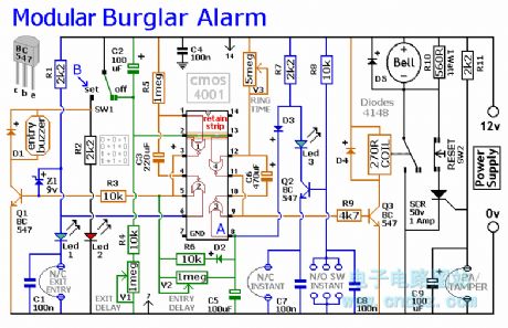
This circuit features automatic Exit and Entry delays and a timed Bell Cut-off. It has provision for both normally-closed and normally-open contacts, and a 24-hour Personal Attack/Tamper zone. It is connected permanently to the 12-volt supply and its operation is enabled by opening SW1. By using the expansion modules, you can add as many zones as you require; some or all of which may be the inertia (shock) sensor type. All the green LEDs should be lighting before you open SW1. You then have up to about a minute to leave the building. As you do so, the Buzzer will sound. It should stop sounding when you shut the door behind you. This indicates that the Exit/Entry loop has been successfully restored within the time allowed. When you re-enter the building you have up to about a minute to move SW1 to the off position. If SW1 is not switched off in time, the relay will energise and sound the main bell. It will ring for up to about 40 minutes. But it can be turned off at any time by SW1. The Instant zone has no Entry Delay. If you don't want to use N/O switches, leave out R8, C8 and Q2; and fit a link between Led 3 and C7. The 24 Hour PA/Tamper protection is provided by the SCR/Thyristor. If any of the switches in the N/C loop is opened, R11 will trigger the SCR and the bell will ring. In this case the bell has no time limit. Once the loop is closed again, the SCR may be reset by pressing SW2 and temporarily interrupting the current flow. The basic circuit will be satisfactory in many situations. However, it's much easier to find a fault when the alarm is divided into zones and the control panel can remember which zone has caused the activation. The expansion modules are designed to do this. Although they will work with the existing instant zone, they are intended to replace it. When a zone is activated, its red LED will light and remain lit until the reset button is pressed. All the modules can share a single reset button. The Stripboard layout of the prototype is available. (View)
View full Circuit Diagram | Comments | Reading(952)
The demon daming curse audio circuit of scan detection type
Published:2011/7/6 0:54:00 Author:Borg | Keyword: demon daming curse, audio circuit
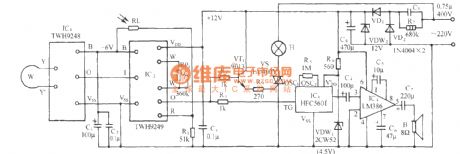
See as the circuit, it includes the TWH9248/9249 radar scanning detecting/processing control coupled module, SCR lighting circuit, curse sound generating and audio power amplifier circuit and AC step-down rectifier circuit, etc, which can be used in the Buddha hall and Canon House for auto security, the aim is to fulfill the unmanned intelligent burglarproof.
(View)
View full Circuit Diagram | Comments | Reading(733)
Computer Protection Circuit
Published:2011/7/6 8:55:00 Author:Robert | Keyword: Computer, Protection
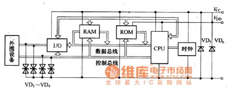
The computer protection circuit is shown in the picture. There are bipolar transient voltage suppression diodes VD1-VD4 connecting with the interface circuit between the computer and the peripherals. They could suppress the over-voltage pulses coming from the computer's peripheral devices. Also there are unipolar transient voltage suppression diodes VD5, VD6 separately being installed in the computer working power's input port. They could suppress the over-voltage pulses coming from the power.
The picture shows the computer protection circuit. (View)
View full Circuit Diagram | Comments | Reading(801)
RF power control circuit
Published:2011/7/6 2:42:00 Author:Christina | Keyword: RF, power control
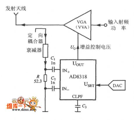
The working principle of the RF power control circuit is as shown in the figure. The controlled object can be the power amplifier (PA), the variable gain amplifier (VGA) and the variable voltage attenuator (VVA).etc. When you are selecting the control mode, you need to cut off the USET and UOUT pins. The measured RF power signal adds to the input port of the AD8318 through the directional coupler and the attenuator. The set voltage of AD8318 is got from the D/A converter (DAC). The gain control voltage which is output by the UOUT of AD8318 can be used to control the output power of VGA(or VVA).
(View)
View full Circuit Diagram | Comments | Reading(748)
High gear stepping dimmer controller circuit (2)
Published:2011/6/28 1:51:00 Author:Ecco | Keyword: High gear, stepping , dimmer , controller
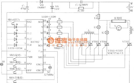
The chart shows the high gear stepping dimmer controller circuit, which has the following functions: It has four gears of stong, medium, weak, extinguish to control the timing of light E1 in 1h, 2h , 4h and 8h; On the other hand, it can control a way of wall lights being in on and off state and another way of fluorescent lights in working state. The device in the core of the circuit is a BA3102 fan control ASIC, and it has three wind-speed control of strong, medium and weak; it has 8h four-stage non-progressive electronic timing(1,2,4,8 h); it has two non-independent control outputs.
(View)
View full Circuit Diagram | Comments | Reading(604)
Simple mixing dimmer circuit
Published:2011/6/28 2:12:00 Author:Ecco | Keyword: Simple, mixing dimmer
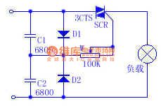
When the capacitor is connected in the sinusoidal AC circuit, the maximum voltage and current will have 90 ° phase difference. According to this theory, the C1 and C2 are connected in series to form the difference, and it is more stable than the connection of resistors and capacitors in series. In the circuit, D1 and D2 rectify respectively positive half-wave and negative half-wave of power, and then it is added to the A trigger and C1 or C2 begins charging. Further using W can change the trigger time for shift-phase, as long as the adjustment of W resistance, you can achieve the purpose of changing the output voltage.
(View)
View full Circuit Diagram | Comments | Reading(601)
The audio control circuit
Published:2011/7/6 4:39:00 Author:qqtang | Keyword: audio control

View full Circuit Diagram | Comments | Reading(966)
The 51 watchdog circuit
Published:2011/7/6 4:36:00 Author:qqtang | Keyword: watchdog circuit
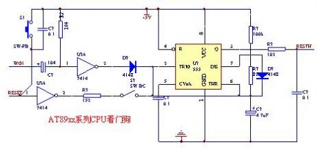
The feed interval of the circuit is less than 3S, the feeding pulse is higher than 5uS, usually, the intermittent pins or pins with period signal keys can be used, just don't affect the former functions.
(View)
View full Circuit Diagram | Comments | Reading(802)
The 4-word control keypad circuit
Published:2011/7/6 4:38:00 Author:qqtang | Keyword: control keypad
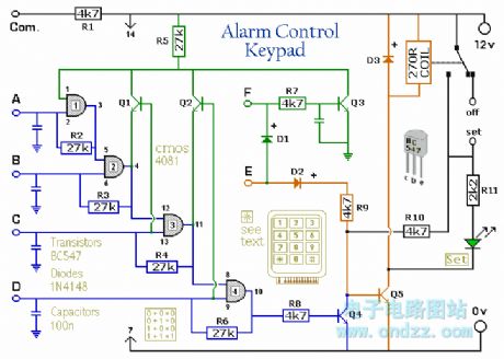
The Keypad must be the kind with a common terminal and a separate connection for each key. On a 12-key pad, look for 13 terminals. The matrix type with 7 terminals will NOT do. The Alarm is set by pressing a single key. Choose the key you want to use and wire it to 'E'. Choose the four keys you want to use to switch the alarm off, and connect them to 'A B C & D'. Your code can include the non-numeric symbols. With a 12-key pad, over 10 000 different codes are available. Wire the common to R1 and all the remaining keys to 'F'. When 'E' is pressed, current through D2 and R9 switches Q5 on. The relay energises, and then holds itself on by providing base current for Q5 through R10. The 12-volt output is switched from the off to the set terminal, and the LED lights. To switch the Alarm off again it is necessary to press A, B, C & D in the right order. The IC is a quad 2-input AND gate, a Cmos 4081. These gates only produce a high output when both inputs are high. Pin 1 is held high by R5. This 'enables' gate 1, so that when 'A' is pressed, the output at pin 3 will go high. This output does two jobs. It locks itself high using R2 and it enables gate 2 by taking pin 5 high. The remaining gates operate in the same way, each locking itself on through a resistor and enabling its successor. If the correct code is entered, pin 10 will switch Q4 on and so connect the base of Q5 to ground. This causes Q5 to switch off and the relay to drop out. Any keys not wired to 'A B C D or E' are connected to the base of Q3 by R7. Whenever one of these 'wrong' keys is pressed, Q3 takes pin 1 low. This removes the 'enable' from gate 1. (View)
View full Circuit Diagram | Comments | Reading(675)
The 6v,2W alarming flash lamp circuit
Published:2011/7/6 4:52:00 Author:qqtang | Keyword: alarming flash lamp
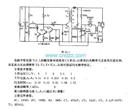
In the circuit, the trigger pulses on the transformer Tr2 are integrated by the capacitor C, so the flash frequency is in proportion to the DC voltage. The DC voltage is imported by the regulators of T2, T3 and T4, so the flash frequency is sure to be constant.Main technology data:Working voltage Us, V: 6 5 4 3.5 3Working current Is, A: 0.34 0.3 0.255 0.23 0.2 Flashing time t, s: 0.39 0.53 0.81 1.08 1.55The converter frequency f, KHz: 8The collecting electrode peak current Ic, A: 1 (regulated by R3) Main element parameters:R1: 560Ω, R2:100Ω R3: 1KΩ C1:470μF, C2: 10μF, C3:0.1μF/400V, T1: BD433. (View)
View full Circuit Diagram | Comments | Reading(827)
| Pages:218/312 At 20201202203204205206207208209210211212213214215216217218219220Under 20 |
Circuit Categories
power supply circuit
Amplifier Circuit
Basic Circuit
LED and Light Circuit
Sensor Circuit
Signal Processing
Electrical Equipment Circuit
Control Circuit
Remote Control Circuit
A/D-D/A Converter Circuit
Audio Circuit
Measuring and Test Circuit
Communication Circuit
Computer-Related Circuit
555 Circuit
Automotive Circuit
Repairing Circuit