
Index 212
Illumination Controller (21)
Published:2011/7/6 6:12:00 Author:Sue | Keyword: Illumination, Controller
When the power is on, the 220v ac voltage will generate +9v voltage on C3 after it is reduced by T, rectificated by UR, filtrated by C4, stablized by IC5. The voltage will be provided to IC1-IC4.
The moment the power is on, +9v voltage will generate a pulse on IC1's Cr terminal(pin 15, reset terminal) through capacitor C2. Then IC1 will be reset. IC1's Y1-Y8 terminals(output terminal) will have low level. Y0 terminal has high level which will turn into low level after it is phase reversed by IC2's inside NOT gate Schmitt trigger D2. The low level will be put on IC3's inside AND GATE circuits(D1-D4) and IC4's inside AND GATE circuits'(D7-D14) a input terminal. Then AND GATE circuits D7-D14 will output low level. The optical coupler VLC1-VLC8 are all disconnected and HL1-HL8 are not illuminated. (View)
View full Circuit Diagram | Comments | Reading(802)
Illumination Controller (20)
Published:2011/7/6 5:54:00 Author:Sue | Keyword: Illumination, Controller
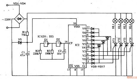
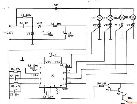
When the first count pulse is sent to IC2's pin 14, IC2's Y0-Y3 terminals output high pulse(when Y0 terminal outputs high level, Y1-Y3 terminals output low level; when Y1 terminal outputs high level, Y0,Y2,Y3 terminals output low level...and the like), VT1-VT4's inside corresponding thyristors are connected in short time. Four circuits of illuminations are illuminated in turn(when IC2's Y0 terminal outputs high level, VT1 is connected, Vm-V are disconnected. HL1 are illuminated. HL2-HLm are not illuminated. When Y2 terminal outputs high level, VT3 is connected and HL3 will be illuminated. HL2 will be off and HL1-HL4 will be off.When Y3 terminal outputs high level, VT4 are connected and HL4 will be illuminated. HL3 will be off. HL1-HL2 will be off.) (View)
View full Circuit Diagram | Comments | Reading(4291)
Illumination Controller (19)
Published:2011/7/6 3:30:00 Author:Sue | Keyword: Illumination, Controller
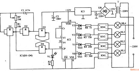
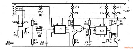
The 220v ac voltage will provide IC1,IC2 with +12v working voltage after it is reduced by T, rectification by UR, filtrated by C3, stablized by IC3.
After the multivibrator begins to work, the oscillate pulse signal generated by it will be put on IC2's pin 14(CP terminal) after it is transformed by trigger RS. The signal will serve as IC2's count pulse. IC2's Y0-Y5 terminals will output high level in turn under the control of count pulse. Then KN1-KN4 will begin to work in turn, which will make HL1-HL4 illuminated in turn.
When IC2's Y0 terminal outputs high level, KN1 begins to work and HL1 is illuminated. Y1-Y5 terminals have low level. KN2-KN4 don't work and HL2-HL4 are not illuminated. (View)
View full Circuit Diagram | Comments | Reading(621)
Illumination Controller (18)
Published:2011/7/6 1:18:00 Author:Sue | Keyword: Illumination, Controller
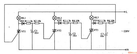
When the ac 220v power is on, VT1 is triggered to be connected. The first group of illuminations HL1 are the first to be illuminated. The ac voltage between VT1's 2 main electrodes will charge C1 after it is rectificated by VD1 and limited by R1.
When C1's voltage reaches a certain value, VT2 is triggered to be connected. The second group of illuminations HL2 are illuminated. The ac voltage between VT2's 2 main electrodes will charge C2 after it is rectificated by VD2 and limited by R3.
When C2's voltage reaches a certain value, VT3 is triggered to be connected. The 3rd group of illuminations HL3 are illuminated. The ac voltage between VT3's 2 main electrodes will charge C3 after it is rectificated by VD3 and limited by R5. (View)
View full Circuit Diagram | Comments | Reading(590)
Illumination Controller (17)
Published:2011/7/5 7:44:00 Author:Sue | Keyword: Illumination, Controller
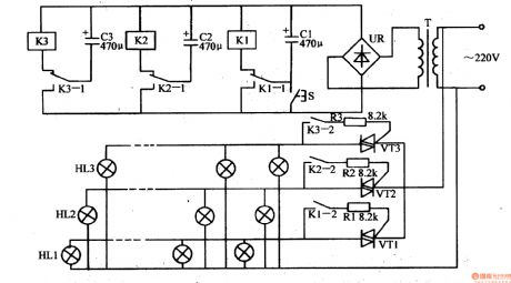
When S is pushed, C1 will be charged quickly. When S is released, C1 will be discharged through K1. K1's normally open trigger is connected and its normally closed trigger is disconnected. C2 is charged quickly.
After C1 is charged, K1 is released. Its normally open trigger is disconnected and its normally closed trigger is connected. C2 discharges K2 through K1 which will make K2 connected. K2's normally open trigger is connected and its normally closed trigger is disconnected.
After C2 is charged, K2 is released. Its normally open trigger is disconnected and its normally closed trigger is connected. C3 discharges K3 through K2's normally closed trigger which will make K3 connected. K2's normally open trigger is connected and its normally closed trigger is disconnected. (View)
View full Circuit Diagram | Comments | Reading(599)
Illumination Controller (16)
Published:2011/7/5 7:28:00 Author:Sue | Keyword: Illumination, Controller
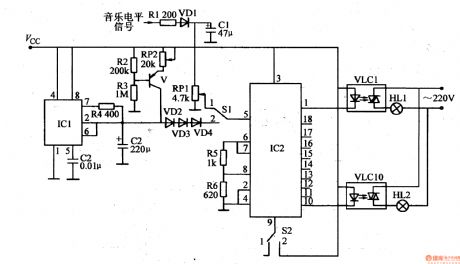
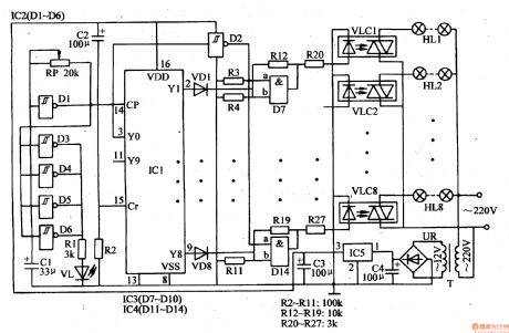
When S1 is put on 1 , IC2 will be controlled by musical level signals and the control circuit will serve as illuminations level indicator. When S1 is put on 2 , IC2 will be controlled by scan pulse signals output by linear scan voltage generator and the control circuit will serve as running illuminations circuit.
When S2 is put on 1 , the illuminations are in punctiform display mode. When S2 is put on 2 , the illuminations are in filiform display mode. IC2's output terminals output high level under the control of scan pulse signals which will make illuminations on by VLC1-VLC10. (View)
View full Circuit Diagram | Comments | Reading(586)
Illumination Controller (15)
Published:2011/7/5 7:18:00 Author:Sue | Keyword: Illumination, Controller
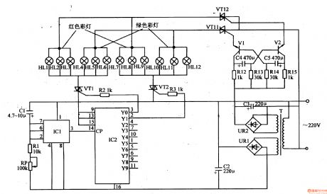
The 220v voltage will generate +9v voltage after reduction, rectification and filtration. One circuit will provide the multivibrator with working power, and the other circuit will provide IC1 and IC2 with working power.
After the pulse generator begins to work, IC2's Y0-Y9 will output high level in turn which will make VT1-VT10 connected.
After the multivibrator begins to work, VT11 and VT12 will be illuminated in turn which will make the red lights and green lights illuminated in turn. (View)
View full Circuit Diagram | Comments | Reading(598)
Illumination Controller (14)
Published:2011/7/5 7:10:00 Author:Sue | Keyword: Illumination, Controller
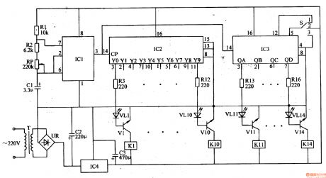
The 220v voltage will provide IC1-IC3 and K1-K14 with working voltage after reduction, rectification, filtration and stablization.
When IC2' and IC3's terminal outputs high level, its outside LED will be illuminated. The transistor will be connected and relay will be connected. Its normally open contractor will make the working power on. The illuminations will be illuminated. For example, when IC2's pin 3 outputs high level, VL1 is illuminated and V1 is connected. K1 is connected and the first circuit of illuminations are illuminated. When IC3's QA terminal outputs high level, VLII is illuminated and VII is connected. KII is connected and the II circuit of illuminations are illuminated. (View)
View full Circuit Diagram | Comments | Reading(639)
Illumination Controller (13)
Published:2011/7/5 6:58:00 Author:Sue | Keyword: Illumination, Controller
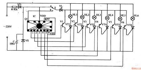
After IC is connected, RPT terminal and Vss are connected together. Its pin 1-6 will output low level in turn. Then HL1-HL6 will be illuminated in turns under the control of V1-V6 and VT1-VT6. When IC's 1 terminal outputs low level, its pin 2-6 will have high level. V1 is connected which will make VT1 connected, andHL1 will be illuminated. When IC's 2 terminal outputs low level, V2 is connected which will make VT2 connected, and the HL2 will be illuminated. When IC's pin 6 outputs low level, V6 is connected which will make VT6 connected, and HL6 will be illuminated. (View)
View full Circuit Diagram | Comments | Reading(609)
Illumination Controller (12)
Published:2011/7/5 6:48:00 Author:Sue | Keyword: Illumination, Controller
The monostable trigger is controller by the electronic switch circuit and the signals emitted by V2. V1 is disconnected when the network's voltage is 0 and is connected on other occasions. When V1 is connected, the +9v votage will charge C2 through V1 and R4 which will make IC1's pin 2's voltage become higher. When the voltage is higher than half of pin 5's control voltage, pin 7 will be disconnected. When V1 is disconnected, C2 will be discharged through VD5 and R2, which will make IC1's pin 2's voltage become lower. When the voltage is lower than half of pin 5's voltage, pin 7 will have a high resistance value. C2's voltage's change frequency is about 20ms and the waveform is similar to sawtooth wave form. (View)
View full Circuit Diagram | Comments | Reading(590)
Illumination Controller (36)
Published:2011/7/7 7:24:00 Author:Sue | Keyword: Illumination, Controller
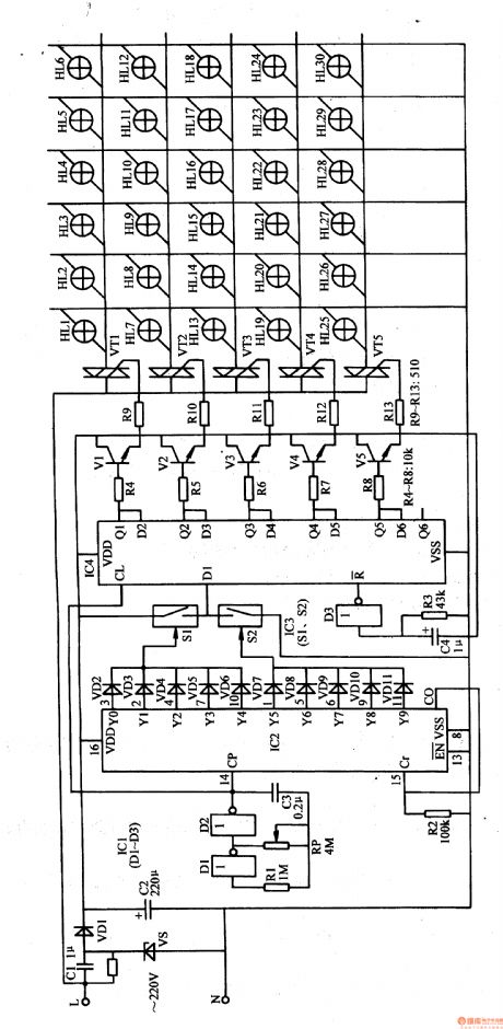
The 220v ac voltage will provide IC1-IC4 and V1-V5 with nearly 12v direct current working voltage after it is reduced by C1, stablized by VS, rectificated by VD1, filtrated by C2.
After the multivibrator begins to work, it will output oscillate pulse signals with a frequency of 2Hz which will provide IC2 with count pulse. Under the control of IC2's count pulse, Y0-Yg terminals will output high level in turn.
C4,R3,D3 will constitute IC4's reset circuit which will provide IC4 with reset pulse after it is connected. Then IC4 is reset, Q1-Q5 terminals will output low level. V1-V5 and VT1-VT5 will be disconnected. HL1-HL30 are all not illuminated. (View)
View full Circuit Diagram | Comments | Reading(592)
Illumination Controller (35)
Published:2011/7/7 7:14:00 Author:Sue | Keyword: Illumination, Controller
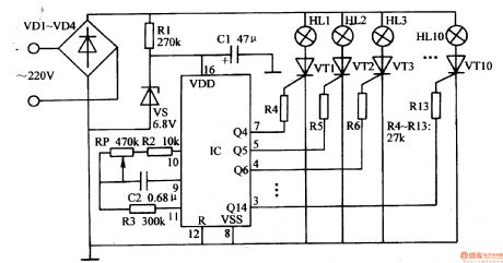
The 220v ac voltage will provide IC with 6.8v direct current working voltage after it is rectificated by VD1,VD4, limited and reduced by R1, stablized by VS, filtrated by C1.
RP,R2,R3,C2 and IC's pin 9-11's inside circuits will constitute multivibrator. After the power is on, the multivibrator will begin to work. After the oscillate signals generated by the multivibrator is frequency divided and counted by IC, IC's Q4-Q10 terminals and Q12-Q14 terminals will output changing control level which will make VT1-VT10 connected intermittently. Illuminations HL1-HL10 will twinkle with different frequency.(The twinkle frequency of HL1 is the highest while the frequency of HL10 is the lowest.)
By adjusting RP's resistance value, the illumination frequency can be changed. (View)
View full Circuit Diagram | Comments | Reading(620)
Illumination Controller (34)
Published:2011/7/7 6:52:00 Author:Sue | Keyword: Illumination, Controller
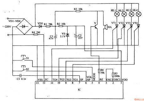
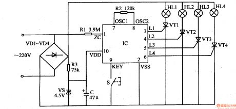
The 220v ac voltage will provide IC with 4.7v direct current voltage after it is limited and reduced by R1,C1, stablized by VS,rectificated by VD2, filtrated by C2,R3,C3.
After IC begins to work, its pin 13-16(L1-L4 terminals) will output changing trigger control signals. By controlling VT1-VT4's working states, HL1-HL4's illumination effects can be controlled. IC's pin 4 and pin 5 will output audio signals which will drive BL to make music after it is amplified by V1,V2.
S is illumination modesselector button. When S is pushed, the illumination modes will be changed. (View)
View full Circuit Diagram | Comments | Reading(635)
Illumination Controller (33)
Published:2011/7/7 6:55:00 Author:Sue | Keyword: Illumination, Controller
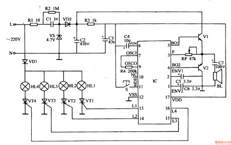
The 220v ac working voltage will provide IC and audio amplifier circuit with 4.5-4.7v direct current working voltage after it is limited and reduced by R1,C1, stablized by VS, rectificated by VD2, filtrated by C2.
After IC begins to work, its pin 7(audio signals output terminal) will output audio signals which will drive BL to make music after it is amplified by audio power amplifier circuit. IC's pin 10-13(L1-14 terminals) will output trigger control signals whichwill change with audio signals. By changing the working states of VT1-VT4, HL1-HL4's illumination effects can be changed.
S1 is illumination modesselector button. When S1 is pushed, illumination mode can be changed. When S1 is pushed continuously, the 7 illumination modes can be changed circularly.
S2 is volume control button. When S2 is pushed continuously, BL's volume can be changed as the order of HIGH-MEDIUM-LOW-NONE-HIGH . (View)
View full Circuit Diagram | Comments | Reading(512)
Illumination Controller (32)
Published:2011/7/7 6:55:00 Author:Sue | Keyword: Illumination, Controller
The 220v ac voltage will provide IC and audio amplier circuit with 5v direct current voltage after it is ruduced by C1, stablized by VS, rectificated by VD2, filtrated by C2,R2,C3.
After IC begins to work, it's pin 10-13(L1-L4 terminals) will output trigger control signals. By controlling the working states of VT1-VT4, illumination effects of illuminations HL1-HL4 will be controlled. At the same time, IC's pin 9 will output musical signals which will drive BL to make music after it is amplified by V1,V2.
S is the control button which controls illumination effects and volume. When S is pushed, the illumination effects and BL's volume will change. (View)
View full Circuit Diagram | Comments | Reading(633)
Illumination Controller (31)
Published:2011/7/7 6:14:00 Author:Sue | Keyword: Illumination, Controller
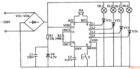
The 220v ac voltage will provide IC with 4.5v direct current working voltage after it is rectificated by VD1-VD4, limited and reduced by R1, stablized by VS, filtrated by C1.
After IC begins to work, its pin 1-4 will output trigger control signals. By controlling the working states of VT1-VW, illumination modes of the illuminations will be changed according to actual requirement. At the same time, IC's inside musical circuit will drive HA to make music directly.
S is the button which controls illumination modes choice and volume. When S is pushed, the illumination modes are changed and HA's volume is changed. (View)
View full Circuit Diagram | Comments | Reading(576)
Illumination Controller (30)
Published:2011/7/7 6:07:00 Author:Sue | Keyword: Illumination, Controller
The 220v ac voltage will be put on HL1-H after it is rectificated by VD1-VD4. The other circuit will provide IC with 5v direct current working voltage after it is isolated by VD5, limited by R1,R2, filtrated by C1,C2, stablized by VS. The ac voltage is also put on IC's pin 12 after it is limited and reduced by R4. It can serve as ac synchronizing signals.
IC's pin 8-11(TG1-TG4 terminals) will serve as trigger control signals output terminals. The trigger signals output by these terminals will control the working states of VT1-VW to control the illumination modes of illumination HL1-HL4.
IC's pin 4 (BZ terminals) serve as musical signals output terminal. The musical signals can promote HA to make sound after it is amplified by V.
S1 is illumination modes control button. When S1 is pushed, illumination modes can be changed. (View)
View full Circuit Diagram | Comments | Reading(582)
Illumination Controller (28)
Published:2011/7/7 5:53:00 Author:Sue | Keyword: Illumination, Controller
The 220v ac voltage will provide IC with 4.5v direct current working voltage after it is rectificated by VD1-VD4, limited and reduced by R3, stablized by VS, filtrated by C. The other circuit will provide IC's pin 1 with ac synchronizing signal through R1.
After IC begins to work, its pin 3-6(L1-M terminals) will output trigger control signals.By controlling the working states of VT1-VW, HL1-KH will change the illumination modes automatically.
S is manual control button. By pushing S, illumination modes can be choosed manually. (View)
View full Circuit Diagram | Comments | Reading(656)
Illumination Controller (27)
Published:2011/7/7 5:45:00 Author:Sue | Keyword: Illumination, Controller
The 220v ac voltage will provide IC with 5v working voltage after it is reduced by T, rectificated by VD1-VD4, stablized by VS, filtrated by C1.
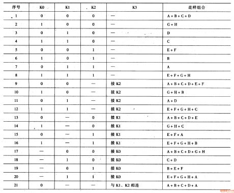
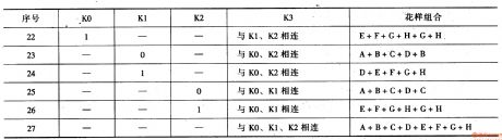
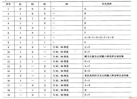
IC's K0-K3 terminals serve as illuminations varied programs set terminals. Q1-Q8 serve as control signals output terminals. When touse the circuit, K0-K3 terminals' connection modes can be changed according to actual requirement(see figure 1-5). The conducting states of V1-V8,VT1-VT8 can be controlled by changing Q1-Q8 terminals' output signals.Then illuminations can twinkle according to the given modes. (View)
View full Circuit Diagram | Comments | Reading(632)
Illumination Controller (26)
Published:2011/7/7 5:33:00 Author:Sue | Keyword: Illumination, Controller
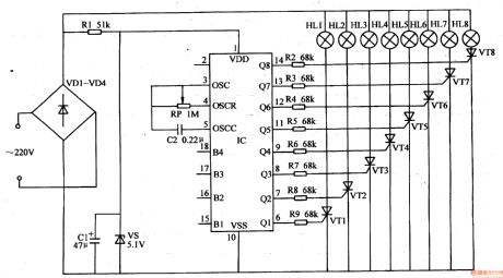
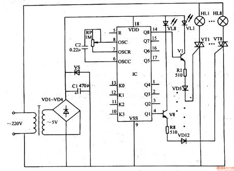
The 220v ac voltage will provide IC with 5v direct current working voltage after it is rectificated by VD1-VD4, limited and reduced by R1, stablized by VS, filtrated by C1.
IC's Q1-Q8 serve as control output terminals. B1-B4 terminals serve as various choices control terminals. By changing the connection settings of B1-B4 terminals, the control signals of Q1-Q8 terminals can be changed.
IC's pin 3-5's inside circuit, RP,C2 constitute oscillate circuit. By adjusting RP's resistance value, illumination cycle frequency of illuminations can be changed.
After IC begins to work, its Q1-Q8 terminals will output changing control signal according to the given program. By controlling the connection and disconnection states of VT1-VT8 by R2-R9, HL1-HL8 can twinkle according to the given illumination modes. (View)
View full Circuit Diagram | Comments | Reading(631)
| Pages:212/312 At 20201202203204205206207208209210211212213214215216217218219220Under 20 |
Circuit Categories
power supply circuit
Amplifier Circuit
Basic Circuit
LED and Light Circuit
Sensor Circuit
Signal Processing
Electrical Equipment Circuit
Control Circuit
Remote Control Circuit
A/D-D/A Converter Circuit
Audio Circuit
Measuring and Test Circuit
Communication Circuit
Computer-Related Circuit
555 Circuit
Automotive Circuit
Repairing Circuit