
Index 195
Motorcycle anti-thief alarm circuit (10)
Published:2011/7/19 21:23:00 Author:TaoXi | Keyword: Motorcycle, anti-thief, alarm
The principle of the circuit
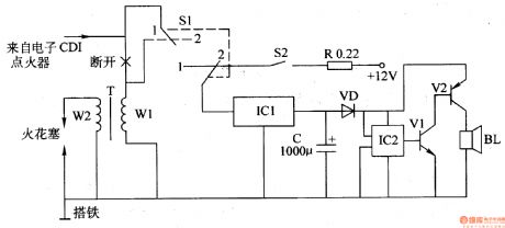
The motorcycle anti-thief alarm circuit is composed of the anti-theft control switch S1, the mercury switch S2, the current-limit resistor R, the three-port voltage stabilization circuit IC1, the filter capacitor C, the diode VD, the alarm sound integrated circuit lC2, the transistors V1 and V2, the speaker BL, the circuit is as shown in figure 7-93.
Components selection
R uses the 5W fusing resistor.C uses the 16V aluminum electrolytic capacitor.VD uses the 1N4001 or 1N4007 silicon rectifier diode.Vl uses the S9013 silicon NPN transistor; V2 uses the S8550 silicon PNP transistor.lCl uses the LM7805 three-port voltage integrated circuit; IC2 uses the KD9561 four tones sound IC.
(View)
View full Circuit Diagram | Comments | Reading(613)
Motorcycle anti-thief alarm circuit (9)
Published:2011/7/19 21:05:00 Author:TaoXi | Keyword: Motorcycle, anti-thief, alarm circuit
The principle of the circuit
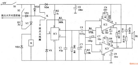
The motorcycle anti-thief alarm circuit is composed of the detection control circuit, the voice generator and the audio power amplifier output circuit, the circuit is as shown in figure 7-92.
The detection control circuit is composed of the power switch S1, the mercury switch S2, the diodes VDl-VD3, the resistor RI, the transistor VT and the relay K.
The voice generator circuit is composed of the diode VD4, the voltage stabilization diode VS, the resistors R2 and R3, the capacitor Cl and the analog voice integrated circuit ICl.
The udio power amplifier output circuit is composed of the audio power amplifier integrated circuits IC2 and IC3, the resistors R4-Rl0, the capacitors C2-C10 and the speaker BL.
(View)
View full Circuit Diagram | Comments | Reading(653)
Motorcycle anti-thief alarm circuit (8)
Published:2011/7/19 20:45:00 Author:TaoXi | Keyword: Motorcycle, anti-thief, alarm circuit

The principle of the circuit
The motorcycle anti-thief alarm circuit is composed of the anti-theft detection circuit, the control circuit, the sound generator, the audio oscillator and the power amplifier output circuit, the circuit is as shown in figure 7-91.
The anti-theft detection circuit is composed of the piezoelectric vibration sensor BC, the resistors R3-R7, R18, the capacitors Cl-C3, the diodes VDl-VD3 and the D3, D4 of the four NAND gate IC (Dl-D4).
The control circuit is composed of the transistors Vl and V3, the resistors Rl, R2, Rll-R13.
The sound generator is composed of the resistors R8 and R9, the capacitor C4 and the sound integrated circuit IC2.
(View)
View full Circuit Diagram | Comments | Reading(2595)
Mine charging indicator
Published:2011/7/20 2:53:00 Author:TaoXi | Keyword: Mine, charging, indicator
The principle of the circuit
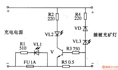
The mine charging indicator is composed of the electrical resistor R1-R5, the fuse FU, the circuit is as shown in figure 8-36.
When the storage battery is charging, the V conducts, the VL2 turns on. When the storage battery is full, the V cuts off, the VL2 turns off.
When the polarity connection of the storage battery is correct, the VL3 will not light. If the polarity connection of the storage battery is reverse, the VL will turn on to send out the yellow alarm signal.
Components selection
The R1-R4 use the 1/4W metal film resistor; R5 use the 2W wirewound resistor.The VD uses the 1N4007 rectifier diode.The VL1-VL3 use the φ5mm high-brightness light-emitting diode.The V uses the S8050 silicon NPN transistor.
(View)
View full Circuit Diagram | Comments | Reading(1599)
74 series digital circuit 74178, 74179 4-bit parallel accessing shift register
Published:2011/7/19 2:49:00 Author:TaoXi | Keyword: 74 series, digital circuit, 4-bit, parallel, accessing, shift, register
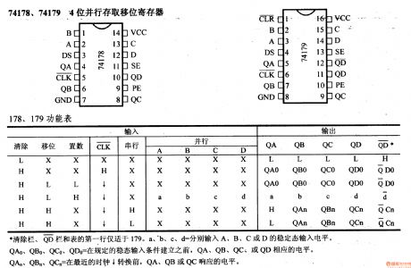
74 series digital circuit 74178, 74179 4-bit parallel accessing shift register
(View)
View full Circuit Diagram | Comments | Reading(3494)
74 series digital circuit 74176 presetable decimal counter
Published:2011/7/19 2:55:00 Author:TaoXi | Keyword: 74 series, digital, presetable, decimal counter
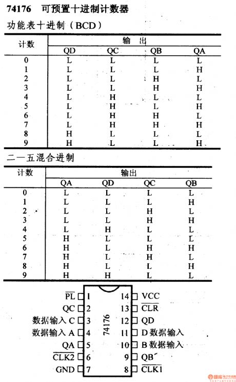
View full Circuit Diagram | Comments | Reading(811)
74 series digital circuit 74175, 74LS175 quad D-type trigger (with the clear port)
Published:2011/7/19 2:58:00 Author:TaoXi | Keyword: 74 series, digital circuit, quad, D-type, trigger, clear port
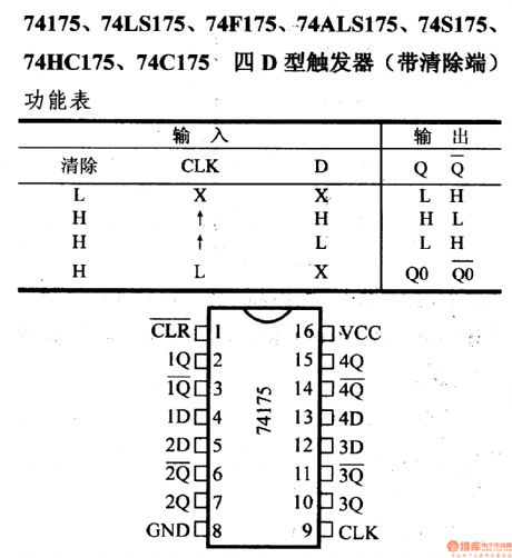
74 series digital circuit 74175, 74LS175 quad D-type trigger (with the clear port)
(View)
View full Circuit Diagram | Comments | Reading(5546)
74 series digital circuit 74174, 74LS174 six D-type trigger (with the clear port)
Published:2011/7/19 3:01:00 Author:TaoXi | Keyword: 74 series, digital circuit, six D-type, trigger, clear port

View full Circuit Diagram | Comments | Reading(3063)
74 series digital circuit 74173, 74LS173 4-bit D-type registers (three states)
Published:2011/7/19 3:05:00 Author:TaoXi | Keyword: 74 series, digital circuit, 4-bit, D-type, register, three states
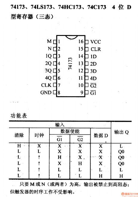
74 series digital circuit 74173, 74LS173 4-bit D-type register (three states)
If the M or N is in the high state, the output is disabled to the high impedance state; but the operating of the timing sequence will not be influenced. (View)
View full Circuit Diagram | Comments | Reading(4220)
74 series digital circuit 74172 multi-port register array (three states)
Published:2011/7/19 3:10:00 Author:TaoXi | Keyword: 74 series, digital circuit, multi-port, register, array, three states
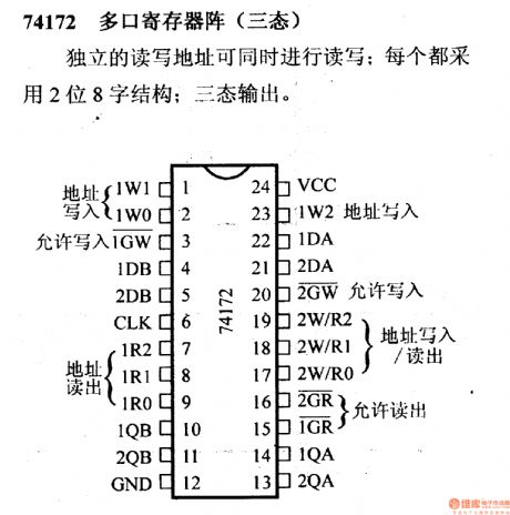
Independent reading and writing addresses can read and write at the same time; every address uses the 2-bit 8-word structure and the three-state output.
(View)
View full Circuit Diagram | Comments | Reading(677)
74 series digital circuit 74170, 74LS170 4×4 register arrays (OC)
Published:2011/7/19 3:18:00 Author:TaoXi | Keyword: 74 series, digital circuit, 4×4, register arrays, OC
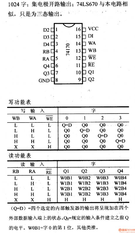
1024 words: the open-collector output; the 74LS670 is similar with this circuit, but the 74LS670 is the three-state output.
The reading and writing addresses are separated, so the reading and writing can be operated at the same time; the storage time typical value is 20ns to form the 4-bit 4-word (can be expanded to n-bit).
(View)
View full Circuit Diagram | Comments | Reading(1834)
74 series digital circuit 74LS375 4-bit bistable D-type latch
Published:2011/7/15 4:28:00 Author:TaoXi | Keyword: 74 series, digital circuit, 4-bit, bistable, D-type, latch
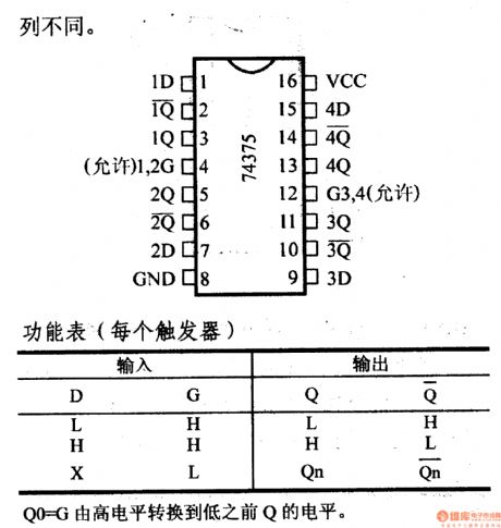
The 74LS375 and 74HC375 4-bit bistable D-type latches has the same electrical performance and function with the 74LS75. The difference between them is the different pin arrangement.
(View)
View full Circuit Diagram | Comments | Reading(2782)
74 series digital circuit 74LS353,74F353 dual 4 to 1 data selectors
Published:2011/7/15 4:33:00 Author:TaoXi | Keyword: 74 series, digital circuit, dual, 4 to 1, data selector
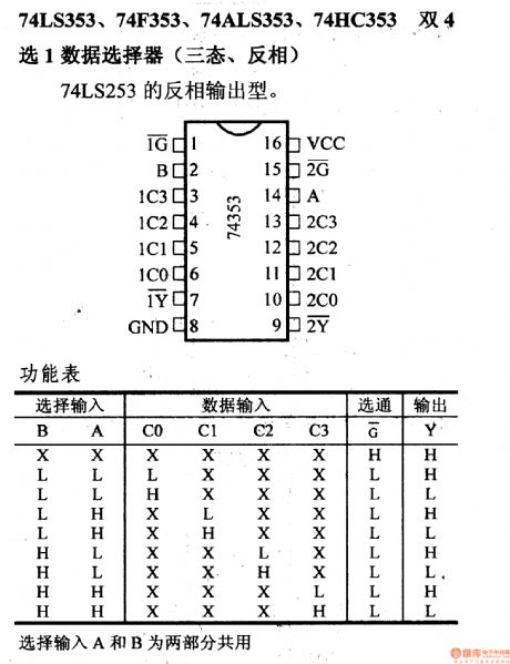
The 74LS353, 74F373, 74ALS353 and 74HC353 dual 4 to 1 data selectors are as shown:
The selective input A and B are the common parts. (View)
View full Circuit Diagram | Comments | Reading(959)
74 series digital circuit 74LS348, 8-3 wire priority encoder (three states)
Published:2011/7/15 4:36:00 Author:TaoXi | Keyword: 74 series, digital circuit, 8-3 wire, priority encoder, three states
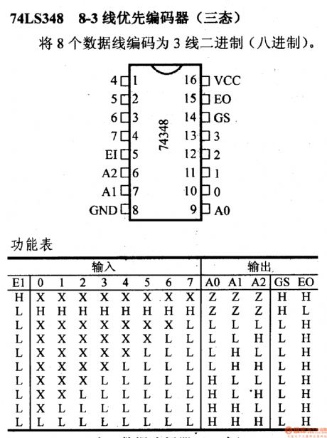
The 74LS348, 8-3 wire priority encoder (three states)
The 8 data lines will be encoded as 3-wire binary system (octonary number system).
(View)
View full Circuit Diagram | Comments | Reading(2976)
74 series digital circuit 74LS260, 74S260 dual 5-input NOR gates
Published:2011/7/15 4:39:00 Author:TaoXi | Keyword: 74 series, digital circuit, dual 5-input, NOR gate
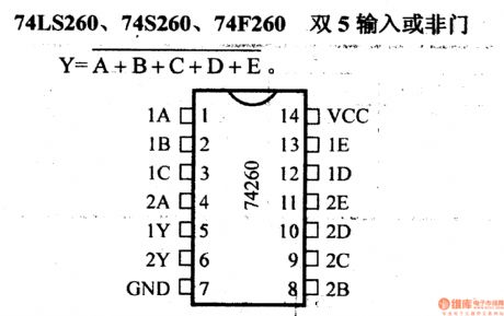
The 74LS260, 74S260 dual 5-input NOR gates are as shown in the figure:
(View)
View full Circuit Diagram | Comments | Reading(1250)
74 series digital circuit 74HC239 dual 2-4 lines decoders/demultiplexers
Published:2011/7/15 4:43:00 Author:TaoXi | Keyword: 74 series, digital circuit, dual, 2-4 lines, decoders, demultiplexers
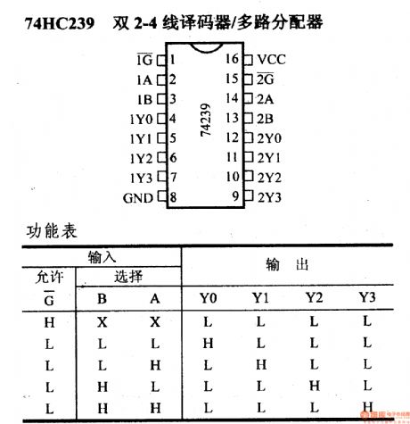
The 74HC239 dual 2-4 lines decoders/demultiplexers:
(View)
View full Circuit Diagram | Comments | Reading(1885)
74 series digital circuit 74HC238,74HCT238 3-8 decoder/demultiplexers
Published:2011/7/15 4:42:00 Author:TaoXi | Keyword: 74 series, digital circuit, 3-8, decoder, demultiplexer
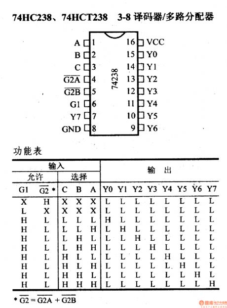
The 74HC238,74HCT238 3-8 decoder/demultiplexers
(View)
View full Circuit Diagram | Comments | Reading(5477)
74 series digital circuit 74HC237, 74ALS237 3-8 line decoders (with address latch)
Published:2011/7/15 4:45:00 Author:TaoXi | Keyword: 74 series, digital circuit, 3-8 line, decoders, address latch
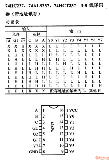
The 74 series digital circuit 74HC237, 74ALS237 3-8 line decoders (with address latch)
(View)
View full Circuit Diagram | Comments | Reading(1488)
74 series digital circuit 74193, 74L193 presetable 4-bit binary system synchronous reversible counters (double clock with clear function)
Published:2011/7/15 5:02:00 Author:TaoXi | Keyword: 74 series, digital circuit, presetable, 4-bit, binary system, synchronous reversible counter, double clock, clear function
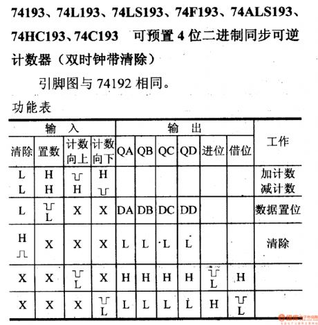
The 74 series digital circuit presetable 4-bit binary system synchronous reversible counters (double clock with clear function)
(View)
View full Circuit Diagram | Comments | Reading(4913)
74 series digital circuit 74185A binary system BCD converter
Published:2011/7/19 1:38:00 Author:TaoXi | Keyword: 74 series, digital circuit, binary system, BCD, converter
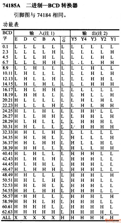
74 series digital circuit 74185A binary system BCD converter
(View)
View full Circuit Diagram | Comments | Reading(2341)
| Pages:195/312 At 20181182183184185186187188189190191192193194195196197198199200Under 20 |
Circuit Categories
power supply circuit
Amplifier Circuit
Basic Circuit
LED and Light Circuit
Sensor Circuit
Signal Processing
Electrical Equipment Circuit
Control Circuit
Remote Control Circuit
A/D-D/A Converter Circuit
Audio Circuit
Measuring and Test Circuit
Communication Circuit
Computer-Related Circuit
555 Circuit
Automotive Circuit
Repairing Circuit