
Electrical Equipment Circuit
Index 60
INSTRUMENT_SERVO_CYCLING
Published:2009/7/24 1:32:00 Author:Jessie
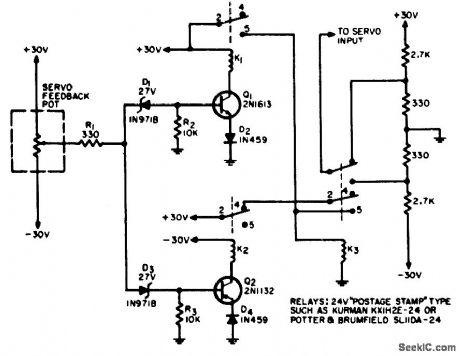
Used to cycle instrument servo units from stop to stop for extended periods of time, as for determining wear characteristics and friction level changes. Motor drive is applied so servo pot arm is driven toward +30 v. When 27-V breakdown of D1 is exceeded, it conducts and turns on 1; K1 pulls in, energizing K3, and motor drive reverses. As pot arm approaches -30 V, reversing action occurs again.-P. J. Stein, Instrument Servo Cycling Circuit, EEE, 12:9, p 61. (View)
View full Circuit Diagram | Comments | Reading(709)
Wideband_log_IF_strip
Published:2009/7/24 0:10:00 Author:Jessie
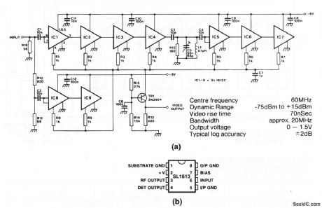
This circuit uses 9 SL1613s to produce a successive-detection log IF strip with the characteristics shown. Figure 2-1B shows the pin connections for the SL1613s. (View)
View full Circuit Diagram | Comments | Reading(0)
VOLTAGE_RATIO_METER
Published:2009/7/24 1:45:00 Author:Jessie
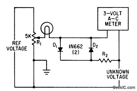
Simple circuit, having resolution better than 0.1% for measuring ratio of two voltages, also serves as accurate null detector when difference voltage is less than 0.5 v. A 115-v, 6-w lamp limits voltage applied to meter when differance voltage exceeds 0.5 v. R2 is chosen to give full-scale defection when difference between the two voltages is maximum.-P. A. Lenk, Circuit Permits Accurate Voltage Ratio Measurements, Electronics, 34:52, p 56-57. (View)
View full Circuit Diagram | Comments | Reading(1077)
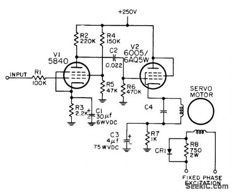
PREFERRED_AMPLIFICATION_1200_PREAM_PLIFIER
Published:2009/7/24 1:39:00 Author:Jessie
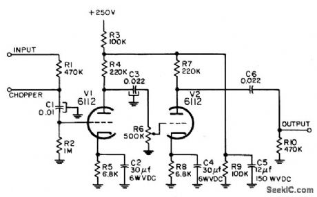
Used with instrument servo motor controller to increase available gain. Chopper is used with d-c outputs only.-NBS, Handbook Preferred Circuits Navy Aero. nautical Electronic Equipment, Vol. I, Electron Tube Circuits, 1963, PC 74, p 74-2. (View)
View full Circuit Diagram | Comments | Reading(704)
400_CPS_PREAMP_FOR_TWO_PHASE_SERVO_MOTOR
Published:2009/7/24 1:35:00 Author:Jessie
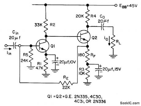
Bias point and gain are stable over wide temperature range, from -55 to 125℃.No selection of transistors is required. Bias design procedure and design equations are given.- Transistor Manual, Seventh Edition, General Electric Co., 1964, p 218. (View)
View full Circuit Diagram | Comments | Reading(711)
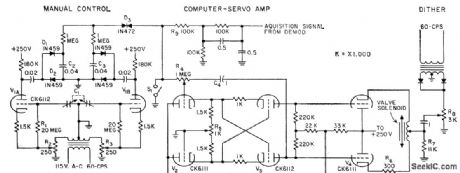
AUTOMATIC_SEARCH_AND_CONTROL
Published:2009/7/24 1:35:00 Author:Jessie
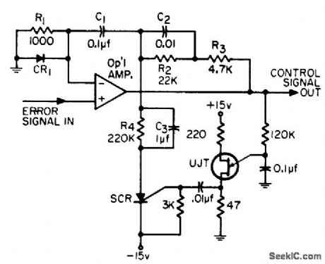
Used in servo control systems when automatic acquisition and linear search are desired, as in aid and phase-lock controls. Basic circuit was used in phase-lock microwave sys terns having 300-kc bandwidth. Active integrator is used as linear search generator as well as control system integrator.-W. H. Schuette, Automatic Search and Control Circuit for Servo Loop, EEE, 12:11, p 67-68. (View)
View full Circuit Diagram | Comments | Reading(686)
SHAFT_POSITION_MODULATOR
Published:2009/7/24 1:31:00 Author:Jessie
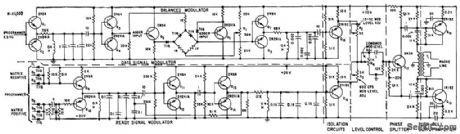
Used for modulating and mixing 1.5-kc data carrier and 600-cps ready signal in system for trans.mitting digitally encoded master shaft positions over phone line at 750 bits per sec and.-R. B. Palmiter, Digital System Positions Shafts Over Phone Line, Electronics, 32:7, p 62-66. (View)
View full Circuit Diagram | Comments | Reading(587)
PREFERRED_INSTRUMENT_SERVO_MOTOR_CONTROLLER
Published:2009/7/24 1:30:00 Author:Jessie
Used to excite control winding of 2-phase Mark 7 Mod 1 and Mark 14 Mod 0 servo motors. Delivers nominal output of 1 W to loads with effective resistance between 2,000 and 4,000 ohms. Maximum output is 50 V. CR1 is 75-ma silicon recliner with 70-V reverse working voltage.-NBS, Hand-book Preferred Circuits Navy Aeronautical Electronic Equipment, Vol. I, Electron Tube Circuits, 1963, PC 70, p 70-2. (View)
View full Circuit Diagram | Comments | Reading(857)
Ultra_low_noise_preamplifier
Published:2009/7/24 0:18:00 Author:Jessie
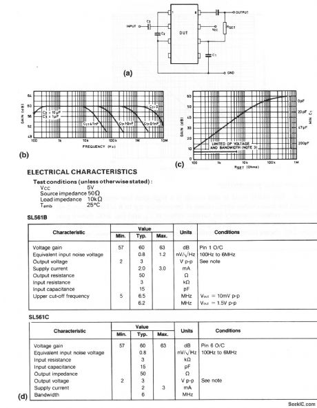

The SL561 used in this circuit is a high-gain low-noise preamplifier designed for audio/video applications at frequencies up to 6 MHz. Figure 2-6B shows gain versus frequency for various values of C1, and Fig. 2-6C shows gain versus various values of RSET. Figure 2-6D shows the electrical characteristics. Figure 2-6E shows harmonic distortion. (View)
View full Circuit Diagram | Comments | Reading(932)
Two_stage_wideband_arnphfier
Published:2009/7/24 0:16:00 Author:Jessie
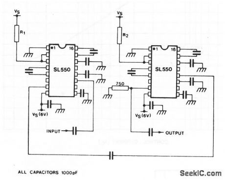
This circuit uses two SL550s (Fig. 2-4), with the first stage connected as a common emitter, and the second stage common base. Stable gains of up to 65 dB can be achieved by the proper selection of R1/R2. The bandwidth is 5 to 103 MHz, with a noise figure slightly greater than 2.0 dB. (View)
View full Circuit Diagram | Comments | Reading(828)
Single_chip_low_noise_wideband_amplifier_with_external_gain_AGC
Published:2009/7/24 0:15:00 Author:Jessie
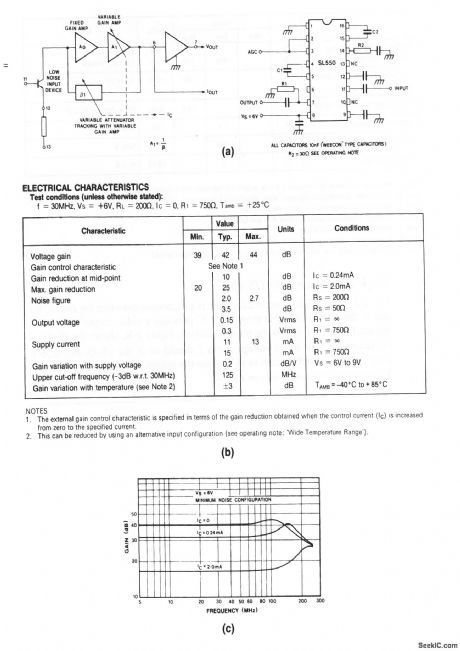
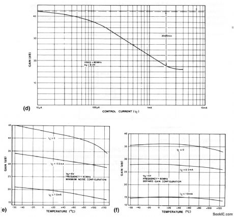
The SL550 used in this circuit is a general-purpose wideband linear amplifier with remote gain/AGC control. Figure 2-4B shows the electrical charac-teristics. Figure 2-4C shows frequency response. The input capacitance (typically 12 pF at 60 MHz) is independent of frequency. The input resistance (about 1.5 kΩ at 10 MHz) decreases with frequency and is typically 500Ω at 60 MHz. Typical gain/ACC voltage is 0.6 V (Ic=1μA) to 0.8 v (IC= 2 mA) applied to pins 2 and 3 (Fig. 2-4D). If full output swing is not required, omit R1, as shown in Fig. 2-4B.A high-impedance output current can be obtained by taking the output from pin 6 (with pin 7 open circuit). Maximum output current is 2 mA peak, with an output impedance of 350 Ω. Gain variation with temperature can be reached (at the expense of noise figure) by decoupling pin 13 and leaving pin 12 open circuit, as shown in Figs. 2-4E and 2-4F. A low input impedance (25 Ω) can be obtained by decoupling pin 11 and applying the input to pin 12 (with pin 13 open circuit). R2 eliminates high-frequency instability, and it can be omitted of the IC is soldered directly to a PC board. (View)
View full Circuit Diagram | Comments | Reading(636)
COMPLETE_3_W_400_CPS_SERVO_AMPLIFIER
Published:2009/7/24 1:28:00 Author:Jessie
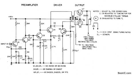
Is capable of driving 3.w servo motor in ambient of -55 to 125℃, if capacitors for 125℃ are used. Gain can be adjusted over range of 20,000 to 80,000 amp per amp by adjusting RF in driver circuit. Gain varies less thon 10% over operating temperature range.- Transistor Manual, Seventh Edition, General Electric Co., 1964, p 225. (View)
View full Circuit Diagram | Comments | Reading(775)
PREFERRED_PHASE_SENSITIVE_NULL_DETECTOR
Published:2009/7/24 1:26:00 Author:Jessie
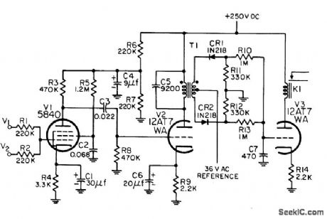
Operates d-c relay when sum of input cur rents is zero. Circuit can be adjusted for any operating frequency from 300 to 1,000 cps by selection of C5 and C7; values given are for 500 cps. Consists of ac amplifier, phase-sensitive detector, and relay control tube.-NBS, Handbook Preferred Circuits Navy Aeronautical Electronic Equipment, Vol. 1, Electron Tube Circuits, 1963, PC 78, p 78-2. (View)
View full Circuit Diagram | Comments | Reading(760)
4_W_SERVO_MOTOR_DRIVE
Published:2009/7/24 1:25:00 Author:Jessie
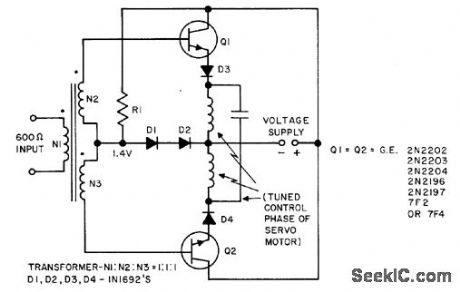
Emitter-follower (common collector) push-pull amplifier gives stable output stage gain along with low-impedance drive for 1 to 4-w servo motors. Forward bias of 1.4 v is developed across D1 and D2, while D3 and D4 protect transistors from inductive load generated voltages that exceed emitter. base breakdown. Efficiency is better thon 60%.- Transistor Manual, Seventh Edition, General Electric Co., 1964, p 223. (View)
View full Circuit Diagram | Comments | Reading(791)
AIDED_TRACKING_SERVO
Published:2009/7/24 1:37:00 Author:Jessie
Telescope is positioned on remote object by radar and then directed by operator, who adds corrections to tracking vector only if tracking rate changes.-R. L. Schaum and D. W. Savage, Joy-Stick Control Aids Telescope Tracking, Electronics, 32:17, p 87-89. (View)
View full Circuit Diagram | Comments | Reading(663)
LOW_FREQUENCY_RANDOM_NOISE_GENERATOR
Published:2009/7/24 2:28:00 Author:Jessie
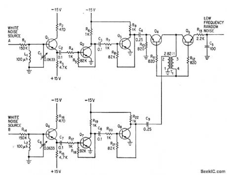
White-noise signals from two sources are filtered, amplified, and fed to symmetrical switching circuit Q4-Q5-T1. On-off switching action of Q4 and Q5 under control of signals gives frequency multiplication required for random output of pulses from about 0 to 5 kc, as required for simulating targets in war games.-R. G. Hundley, Simulating Tactical Radar and Sonar, Electronics, 36:50, p 25-31. (View)
View full Circuit Diagram | Comments | Reading(1157)
SPIRAL_SWEEP_SIMULATOR
Published:2009/7/24 2:27:00 Author:Jessie
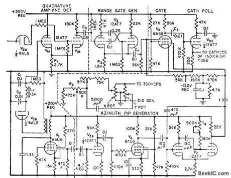
Does not require operational radar equipment. Antenna signal is obtained from phase shifter and sweep amplitude potentiometer that provides spiral sweep for target on oscillosope. Range is indicated by gating target to correct radius of spiral sweep. Azimuth is indicated by another gate that limits target appearance to correct angle on spiral sweep.-J. I. Leskinen, Four Ways to Simulate Radar Targets, Electronics, 31 :23, p 82-86. (View)
View full Circuit Diagram | Comments | Reading(683)
PULSE_COMMUTATOR_SIMULATOR
Published:2009/7/24 2:27:00 Author:Jessie
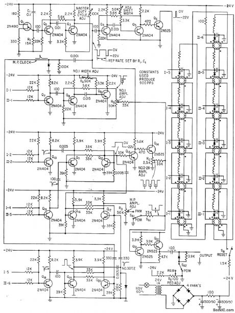
Used for checking telemetry ground station equipment without wearing out commutator of telemeter. Magnetic shift register elements are used as ring counters.-J. Porter, Pulse Commutator Simulator Uses Magnetic Logic elements, Electronics, 34:12, p 43-45. (View)
View full Circuit Diagram | Comments | Reading(736)
TRANSFO_RM_ER_CONTROLLED_SHIFT_REGISTER
Published:2009/7/24 2:02:00 Author:Jessie
Can be built to shift forward, backward, or in n dimensions. With series of flip-flops, stored information can be rearranged arbitrarily, in single pulse.-W. M. Carey, Using Inductive Control in Computer Circuits, Electronics, 32:38, p 31-33. (View)
View full Circuit Diagram | Comments | Reading(704)
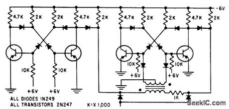
FLIP_FLOP_BUILDING_BLOCKS
Published:2009/7/24 2:02:00 Author:Jessie
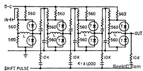
Inductively coupled flip-flops are put together to form shift register. Both signal and shift pulses are positive. Operates reliably over wide ranges of input pulse amplitude and circuit parameters.-M. M. Perugini and N. Lindgren, Recent Progress in Solid State Technology, Electronics, 33:10, p 39-43. (View)
View full Circuit Diagram | Comments | Reading(709)
| Pages:60/126 At 204142434445464748495051525354555657585960Under 20 |
Circuit Categories
power supply circuit
Amplifier Circuit
Basic Circuit
LED and Light Circuit
Sensor Circuit
Signal Processing
Electrical Equipment Circuit
Control Circuit
Remote Control Circuit
A/D-D/A Converter Circuit
Audio Circuit
Measuring and Test Circuit
Communication Circuit
Computer-Related Circuit
555 Circuit
Automotive Circuit
Repairing Circuit