
Electrical Equipment Circuit
Index 50
Temperature/Voltage Monitoring System Circuit Composed Of MAX1298
Published:2011/7/31 20:36:00 Author:Robert | Keyword: Temperature, Voltage, Monitoring, System
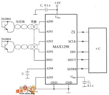
Ad shown in the picture, the circuit could measure two channels of temperature and one channel of battery voltage at the same time. It uses +5V power supply. The temperature sensor's wire shound need the shielded twisted pair. The shielded layer is connected to SHO pin. The C1 is a power noise-reduction capacitor. The C2 is used to filter output the noise of the referenced voltage. By using μC it could set the MAX1298's power working mode and read the MAX1298's output data, and also detect if the +5V power has the faults of under voltage or over voltage. (View)
View full Circuit Diagram | Comments | Reading(580)
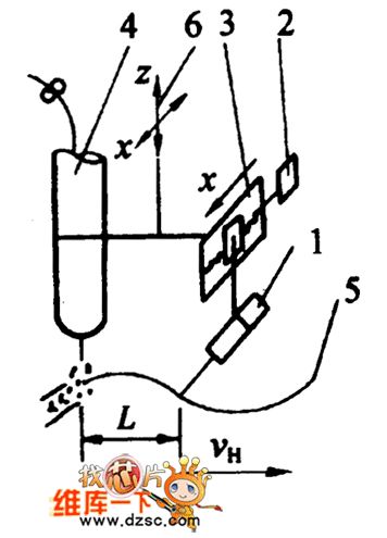
MAGNETIC_TAPE_DATA_SAMPLER
Published:2009/7/23 22:02:00 Author:Jessie
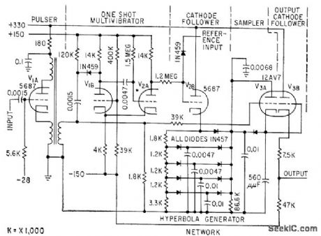
Used in playback system for discrimination of f-m signal from magnetic tape. Compares data channel signals with recorded reference frequency, to make output independent of tape speed. Tube V2B is cathode follower with hyperbola generator network as cathode impedance, to create curve for average area of voltage block at any time during data period for a given block width (1.4 millisec).-P. S. Bengston, Sampling Discriminators for Data Reduction, Electronics, 32:13, p 70-72. (View)
View full Circuit Diagram | Comments | Reading(735)
CONDUCTIVITY_TESTER
Published:2009/7/23 22:01:00 Author:Jessie
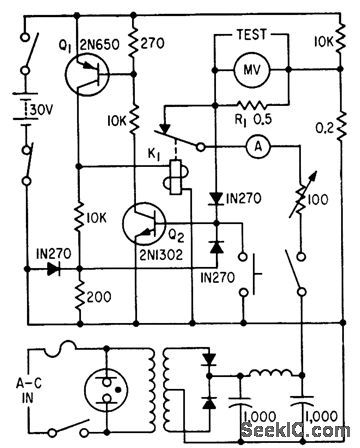
For nondestructive testing of printed-circuit conductors, through hole plating, soldered joints, and coils, in resistance range from 0 to 50 milliohms and currents up to 5 amp. Q1 and Q2 protect millivoltmeter from open-circuit voltage over loads by energizing relay K1, interrupting rectified output from cc power supply.-F. W. Kear, Unit Measures Printed Circuit Resistances, Electronics, 34:4, p 64-65. (View)
View full Circuit Diagram | Comments | Reading(1004)
30_KC_HALL_GENERATOR_SAMPLING_SWITCHES
Published:2009/7/23 22:01:00 Author:Jessie
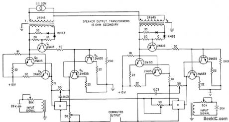
Control current circuits of series-connected Hall generators X are pulsed alternately for switching d-c input signal. Triggering for identical circuit at right occurs on opposite half-cycles of signal generators.-T. J. Marcus, Using Hall Generators as Contactless Commutators, Electronics, 35;4, p 43-45. (View)
View full Circuit Diagram | Comments | Reading(757)
1_kHz_WlEN_BRIDGE
Published:2009/7/5 23:40:00 Author:May
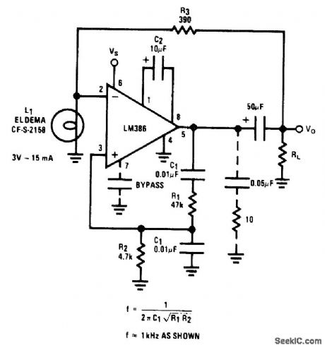
Closed-loop gain of 10, fixed by ratio of R1 to R2, is sufficient to avoid spurious oscillations. Frequency is easily changed by using different values for capacitors C1. R3 and lamp L1 provide amplitu e-stabilizing negative feedback. Supply can be 9 V.- Audio Handbook, National Semiconductor. Santa. Clara. CA, 1977. p 4-30-4-33. (View)
View full Circuit Diagram | Comments | Reading(996)
CHV-CMI48616 Type Induction Cooker Circuit
Published:2011/7/30 19:42:00 Author:Robert | Keyword: Induction Cooker
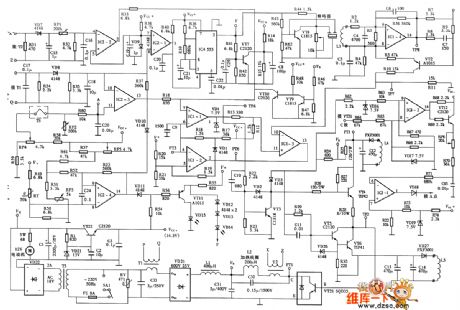
The picture shows the CHV-CMI48616 type induction cooker circuit. (View)
View full Circuit Diagram | Comments | Reading(3483)
l00_MC_NOISE_FIGURE_TEST_SET
Published:2009/7/23 21:54:00 Author:Jessie

Used in measuring upper noise-corner frequency of transistors, by measuring small-signal short-circuit forward current transfer ratio (common emitter) h-fe or f-T.-Texas Instruments, Transistor Circuit Design, McGraw-Hill, N.Y., 1963, p 305. (View)
View full Circuit Diagram | Comments | Reading(785)
Shanghai Sharp R-230B Computer-Type Microwave Oven Circuit
Published:2011/8/2 19:16:00 Author:Robert | Keyword: Shanghai, Sharp, Computer-Type, Microwave Oven
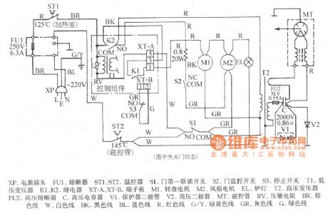
The picture shows the Shanghai Sharp R-230B computer-type microwave oven circuit.
In the picture the XP is voltage plug. The FU1 is fuse. The ST1 and ST2 are temperature controllers. The S1 is door first interlock switch. The S2 is door monitoring switch. The S3 is stopping switch. The T1 is low-voltage transformer. The K1 and K2 are relays. The XT-A, XT-B are terminal board. The M1 is rotating plate motor. The M2 is fan motor. The EL is oven lamp. The T2 is high-voltage transformer. The FU2 is high-voltage fuse. The C is high-voltage capacitor. The V1 is protector diode. The V2 is high-voltage diode. The MT is magnetron. TheRV is varistor. The BR is brown wire. The W is white wire. The BK is black wire. The BL is blue wire. The R is red wire. The G/Y is green/yellow wire. The GR is gray wire. The G is green wire. (View)
View full Circuit Diagram | Comments | Reading(1761)
Shanghai Sharp R-750B Computer-Type Barbecue Microwave Oven Circuit
Published:2011/8/2 19:26:00 Author:Robert | Keyword: Shanghai, Sharp, Computer-Type, Barbecue, Microwave Oven
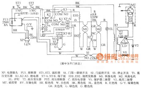
The picture shows the Shanghai Sharp R-750B computer-type barbecue microwave oven circuit.'
In the picture the XP is voltage plug. The FU1 is fuse. The ST1 and ST2 are temperature controllers. The S1 is door first interlock switch. The S2 is door monitoring switch. The S3 is stopping switch. The T1 is low-voltage transformer. The K1, K2, K3 are relays. The XT-A, XT-B are terminal board. The EH1, EH2 are barbecue heater. The M1 is rotating plate motor. The M2 is fan motor. The EL is oven lamp. The T2 is high-voltage transformer. The FU2 is high-voltage fuse. The C is high-voltage capacitor. The V1 is protector diode. The V2 is high-voltage diode. The MT is magnetron. The RV is varistor. The BR is brown wire. The W is white wire. The BK is black wire. The BL is blue wire. The R is red wire. The G/Y is green/yellow wire. The GR is gray wire. The G is green wire. The O is orange wire. (View)
View full Circuit Diagram | Comments | Reading(2160)
Parallel High-Speed Current Driver Circuit Composed Of OPA660
Published:2011/7/30 19:29:00 Author:Robert | Keyword: Parallel, High-Speed, Current, Driver
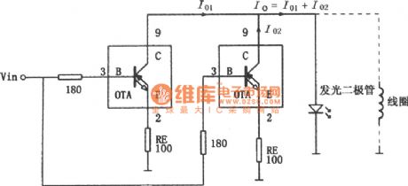
The picture shows the parallel high-speed current driver circuit. The input signal Vin is added to the OPA660 device's equivalent special transistor OTA's base port B (pin 3) through a 180Ω resistor. Two collector ports are connected directly (pin 8) and also connected with the load. They are also supply current to the load. So the current through the load would be twice than a single OTA's current. The OPA660's OTA's maximum output current is ±15mA, but the parallel circuit could provide maximum output current of ±30mA. So when need more current it could take more OPA660 operational amplifiers to be parallel to get the load current needed. The input port (B polar) is connected external 180Ω resistor, which could have the function of current limiting and avoid the self-oscillation of the amplifier and reduce the the peak cases of frequency characteristic. (View)
View full Circuit Diagram | Comments | Reading(735)
FET_MIXER_FOR_UHF_TV_TUNER
Published:2009/7/23 21:51:00 Author:Jessie
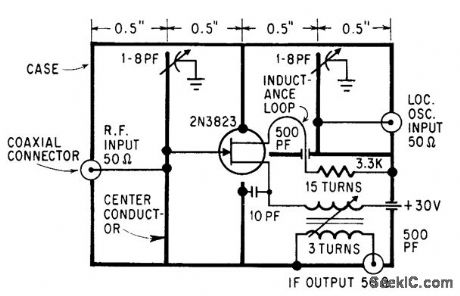
Uses strip transmission lines. Ground-plane conductors divide circuit into three shielded cubicles, for r-f input, local oscillator output, and i-f output.-S. M. Weaver, For a Good Mixer, Add One FET, Electronics, 39:6, p 109-112. (View)
View full Circuit Diagram | Comments | Reading(1015)
CRYOGENIC_CONTACT_TESTER
Published:2009/7/23 21:50:00 Author:Jessie
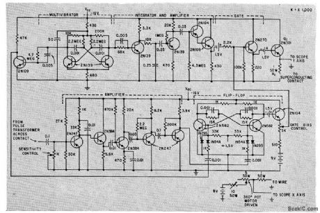
Measures critical current in superconducting contacts during periods shorter than 100 microsec in which such currents can be maintained, and gives oscilloscope display.-J. I. Pankove and R. Drake, Measuring Critical Current in Cryogenic Circuits, Electronics, 33:4, p 52-53. (View)
View full Circuit Diagram | Comments | Reading(740)
Earphone_radio
Published:2009/7/23 21:50:00 Author:Jessie
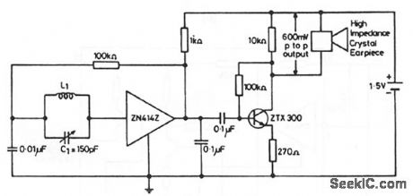
This circuit shows the ZN414Z (Fig. 2-14A) combined with an external amplifier to drive an inexpensive earpiece. This arrangement is generally cheaper than having the ZN414Z drive an expensive sensitive earpiece directly (to produce an ultra-miniature radio). The arrangement also provides for a volume control, if desired. Substitute a 250-Ω potentiometer in series with a 100-Ω fixed resistor for the 270-Ω emitter resistor. L1=80 turns of 0.3-mm diameter enamelled copper wire on a 5-cm or 7.5-cm long ferrite rod. Any value of L1/C1 that gives a high Q at the desired frequency can be used. (View)
View full Circuit Diagram | Comments | Reading(1058)
Low Power Consumption Band-Stop Filter Circuit
Published:2011/7/28 6:29:00 Author:Robert | Keyword: Low, Power Consumption, Band-Stop, Filter
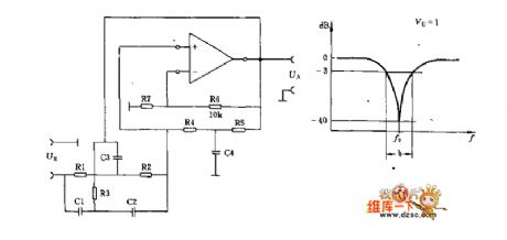
In this circuit the ratio of R6 and R7 would determine the amplification factor Voo in very low frequency. If Vo=1, then the R7 can be cancelled in practice.The selection principle of each elements in this circuit is listed in the picture 2.
500kΩ>R1=R2>1kΩ.0.5uF>C1=C2>200pF.From R1=R2, it has the conclusion that R3=0.5R1. From C1=C2, it has the conclusion that C3=2C1.The quality factor Q=f0/b (-3dB get the point b).It selects R4≈R5=4Q/wC3 and C4=C3/2Q.For example: f0=450Hz, b=250Hz, R1=R2=47kΩ, it has that C1=C2=1/2πf0R=1/2π*450*47*10^3=7.52nF.R3=0.5*4.7kΩ=23.5kΩ.And C3=2C1=15nF.Q=f0/b=450/250=1.8.R4≈R5=4Q/wC3=4*1.8/2π*450*15*10^-9=169kΩ. (View)
View full Circuit Diagram | Comments | Reading(1059)
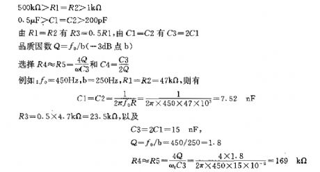
Tracking Device Mechanism Diagram Circuit
Published:2011/7/30 9:12:00 Author:Robert | Keyword: Tracking, Device, Mechanism, Diagram
The picture shows the tracking device mechanism diagram circuit.
The part 1 is sensor. The part 2 is stepper machine. The part 3 is screw nut machanism. The part 4 is welding torch. The part 5 is welding with groove. The part 6 is connector (which is connected with the weldment bidirection adjustment mechanism). (View)
View full Circuit Diagram | Comments | Reading(796)
VIBRATION_TEST_MONITOR
Published:2009/7/23 22:00:00 Author:Jessie
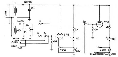
Gives visual indication of momentary contact malfunctions in components during vibration testing. Also indicates permanent open or short. Each channel monitors one component. In testing device having nomally closed contacts, lamp should come on initially. lamp goes out if contacts open momentarily. If lamp remains on offer reset switch for channel is pushed and released, open was momentary. If lamp goes out on release, open is permanent.-Component Vibration Test Monitor, Electronic Circuit Design Handbook, Mactier Pub. Corp., N.Y., 1965, p 159. (View)
View full Circuit Diagram | Comments | Reading(896)
PARALLEL_PATH_CONTINUITY_CHECKER
Published:2009/7/23 21:56:00 Author:Jessie
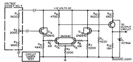
Used for monitoring nonseparable parallel paths for continuity in automatic testing equipment. Current through circuit under rest is limited, to prevent damage to low-power circuits. Resistance levels for continuity checks are set at 5, 20, 100, and 1,000 ohms.-R. H. Wassum, Parallel-Path Continuity-Checking Circuit, EEE, 14:8, p 164-166. (View)
View full Circuit Diagram | Comments | Reading(766)
ELECTROEXPLOSIVE_PULSER
Published:2009/7/23 21:55:00 Author:Jessie
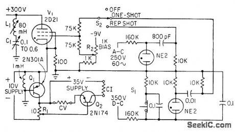
Used in determining energy required to fire 50% of devices being tested. Uses thyratron as pulse generator, transistor for pulse shaping, and power transistor as linear amplifier to give either constant-current or constant-voltage pulses over wide range (0 to 10 v or 0 to 10 amp at durations of 100 to 1,000 microsec).-L. A. Rosenthal, Generator Delivers Constant Current or Voltage Pulses, Electronics, 33:38, p 82-84. (View)
View full Circuit Diagram | Comments | Reading(833)
SIMPLE_TRIANGLE_SQUARE
Published:2009/7/5 22:47:00 Author:May

This circuit generates simultaneously, a triangle and a square waveform. It is self starting and has no latch up problems. IC1 is an integrator with a slew rate determined by CT and RT and IC2 is a Schmitt trigger. The output of IC1 ramps up and down be-tween the hysteresis levels of the Schmitt, the output of which drives the integrator.
By making RT variable, it is possible to alter the operating frequency over a 100 to 1 range. Three resistors, one capacitor, and a dual op amp is all that is needed to make a versatile triangle and square wave oscillator with a possible frequency range of 0.1 Hz to 100 kHz. (View)
View full Circuit Diagram | Comments | Reading(913)
Off_leakage_current_tests
Published:2009/7/23 21:54:00 Author:Jessie
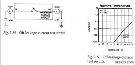
Figure 2-M shows a basic test circuit for measuring off-leakage-current I S(OFF) and I D(OFF) for the MAX326/27. Figure 2-N shows how I S(OFF) changes with temperature (View)
View full Circuit Diagram | Comments | Reading(765)
| Pages:50/126 At 204142434445464748495051525354555657585960Under 20 |
Circuit Categories
power supply circuit
Amplifier Circuit
Basic Circuit
LED and Light Circuit
Sensor Circuit
Signal Processing
Electrical Equipment Circuit
Control Circuit
Remote Control Circuit
A/D-D/A Converter Circuit
Audio Circuit
Measuring and Test Circuit
Communication Circuit
Computer-Related Circuit
555 Circuit
Automotive Circuit
Repairing Circuit