
Electrical Equipment Circuit
Index 41
CHOPPER_AND_PHASE_DETECTOR
Published:2009/7/21 8:01:00 Author:Jessie
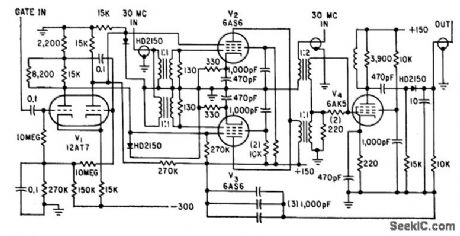
Input gate signal operates Schmitt trigger V1, to give identical but oppositely phased signals for phase detector of instrument for measuring phase differences between two signals.-R. T. Stevens, Precision Phasemeter for CW or Pulsed UHF, Electronics, 33:10, p 54-57. (View)
View full Circuit Diagram | Comments | Reading(836)
TV_video_signal_processor_circuit_2
Published:2009/7/21 8:00:00 Author:Jessie
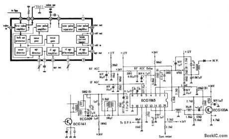
TV video signal processor circuit. The EGG 1065 is a 16-pin DIP (courtesy GTE Sylvania Incorporated). (View)
View full Circuit Diagram | Comments | Reading(719)
Serial_data_transfer_circuit_into_shift_registers_with_parallel_output_to_data_bus
Published:2009/7/21 8:22:00 Author:Jessie
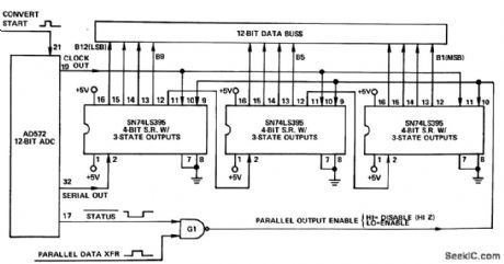
Serial data transfer circuit into shift registers with parallel output to data bus (courtesy Analog Devices, Inc.). (View)
View full Circuit Diagram | Comments | Reading(1517)
MICROWATTS_AT_QUIESCENCE
Published:2009/7/21 8:05:00 Author:Jessie
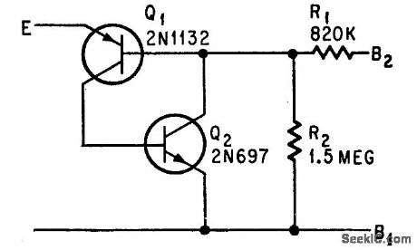
Circuit has same characteristics as single unijunction transistor but dissipates only microwatts of power when off.-R. A. Wilson, Pnp Plus Npn Equals Unijunction transistor, Electronics, 38:5, p 94-95. (View)
View full Circuit Diagram | Comments | Reading(1603)
Cotor_TV_chroma_signal_amplifier
Published:2009/7/21 8:05:00 Author:Jessie
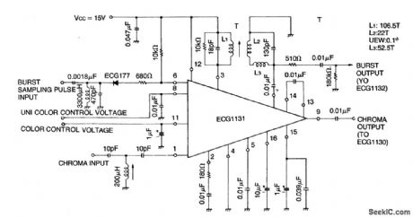
Cotor TV chroma signal amplifier. The EGG 1131 isa 16-pin DIP and conststs of a chromaamplifier, an ACC amplifier, aburst gate amplifier, an ACC peak detector, a color killer, aDC chroma gain control, a DC uni-color control and a balanced sampling circuit forthe burst signal. By connecting the control terminal of the unicolor and contrast terminal of the ECG1131 it is possible to control chroma gain and contrast simultaneously (courtesy GTE Sylvania Incorporated). (View)
View full Circuit Diagram | Comments | Reading(1996)
MOS_48_based_analog_processor
Published:2009/7/21 8:19:00 Author:Jessie
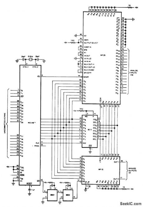
MOS-48 based analog processor. This circuit shows the MP-10 D/A convener and the MP-20 A/D convener connected to the 8748 processor (courtesy Intel Corporation). (View)
View full Circuit Diagram | Comments | Reading(1151)
TV_vertical_sync_delay_circuit
Published:2009/7/21 8:18:00 Author:Jessie
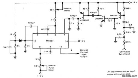
TV vertical sync delay circuit (courtesy Motorola Semiconductor Products Inc) (View)
View full Circuit Diagram | Comments | Reading(1038)
Memory_mapped_output_device_interfaced_with_the_MCS_80_8080A_CPU_system
Published:2009/7/21 8:16:00 Author:Jessie

Memory mapped output device interfaced with the MCS-80 (8080A) CPU system (courtesy Analog Devices, Inc.). (View)
View full Circuit Diagram | Comments | Reading(746)
Full_wave_SCR_bridge_power_supply_for_cotor_TV_rated_at_80_volts_15_amperes
Published:2009/7/21 8:15:00 Author:Jessie
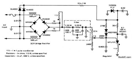
Full-wave SCR bridge power supply for cotor TV rated at 80 volts, 1.5 amperes. This circuit is designed for 19-inch color receivers (courtesy Motorola Semiconductor Products Inc.). (View)
View full Circuit Diagram | Comments | Reading(1970)
Color_TV_chroma_processor
Published:2009/7/21 8:12:00 Author:Jessie
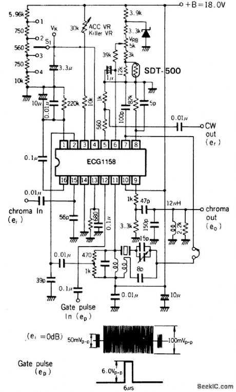
Color TV chroma processor. The ECG1158 includes the functions for chroma amplifier, oscillator, ACC, color killer and color control (courtesy GTE Sylvania Incorporated). (View)
View full Circuit Diagram | Comments | Reading(714)
TV_video_processor
Published:2009/7/21 8:10:00 Author:Jessie
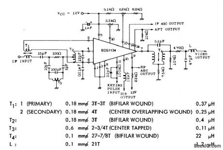
TV video processor. The EGG 1134 contains a picture IF amplifier, avideo detector,a video amplifier,keyed AGC with noise immunity, delayed AGC for thetuner, an AFT amplifier, a sound IF amplifier, asound carrier detector, a4.5 MHz sound carrier amplifier and a reverse AGC voltage for MOS FET tuner. Coil data is shown below schematic (courtesy GTE Sylvania Incorporated). (View)
View full Circuit Diagram | Comments | Reading(2540)
HOURS_OF_DELAY
Published:2009/7/21 9:16:00 Author:Jessie
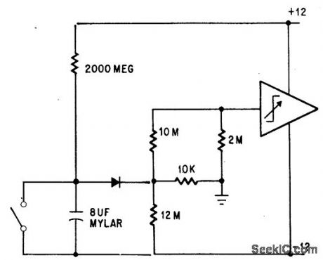
Capacitor starts charging from -12 v to +12 v when switch is opened.Diode begins conducting at ground potential, and operational trigger trips when diode passes 2 na. Timing accuracy is high.-P. Lefferts, Operational Trigger For Precise Control, Electronics, 37:28, p 50-55. (View)
View full Circuit Diagram | Comments | Reading(827)
BALANCED_MODULATOR_DEMODULATOR
Published:2009/7/22 1:14:00 Author:Jessie
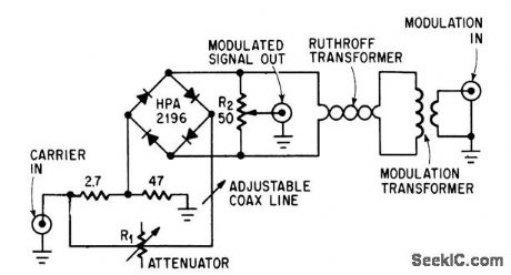
Achieves high carrier and modulation suppression by using closely matched diodes and providing R1 for amplitude adjustment and coaxial line for phase adjustment. R2 provides slight amplitude adjustment.-W. H.Ellis, Diode Quad Modulator Suppresses Carrier 65 Db, Electronics, 39:8, p 97. (View)
View full Circuit Diagram | Comments | Reading(1076)
SIREN_WITH_MUTING
Published:2009/7/22 1:13:00 Author:Jessie
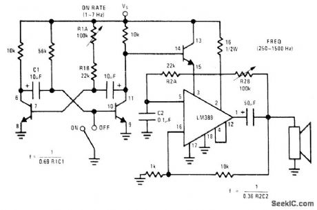
National LM389 array having three transistors and power opamp on same chip uses opamp as square-wave oscillator whose frequency is adjusted with R2B. One transistor is used in muting circuit to gate power amplifier on and off, while other two transistors form cross-coupled MVBR that controls rate of square-wave oscillator.- Audio Handbook, National Semiconductor, Santa Clara, CA, 1977, p 4-33-4-37. (View)
View full Circuit Diagram | Comments | Reading(949)
CROWBAR_IGNITRON
Published:2009/7/21 22:03:00 Author:Jessie
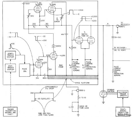
Multimegawatt high-vacuum modulator tubes for large radars are protected during tests by circuit that is triggered by fault sensors. Total response time for firing ignitron crowbar is below 10 microsec.-T. E. Yingst, Circuits to Control and Protect High-Power Modulator Tubes, Eleatronics, 35:4, p 56-61. (View)
View full Circuit Diagram | Comments | Reading(1089)
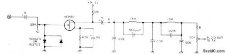
PRECOMPRESSION_SHAPER
Published:2009/7/21 22:03:00 Author:Jessie
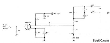
Improves effective signal strength of SSB transmitter by shaping AF frequency response ahead of audio compressor. Low-noise FET preamp providing initial gain for high-impedance microphone is followed by low- and high-rolloff circuit giving 15-dB boost or roll off to frequencies centered at about 1 kHz.-J. J. Schultz, Adding dBs to the Audio Compressor, 73 Magazine, May 1974, p 21-23 and 25. (View)
View full Circuit Diagram | Comments | Reading(1505)
Read_circuitry_of_paper_tape_reader_for_RTL
Published:2009/7/21 21:26:00 Author:Jessie
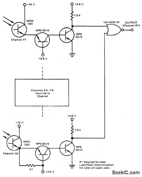
Read circuitry of paper-tape reader for RTL (courtesy Motorola Semiconductor Products Inc.). (View)
View full Circuit Diagram | Comments | Reading(811)
Enlarger_phototimer
Published:2009/7/21 21:36:00 Author:Jessie
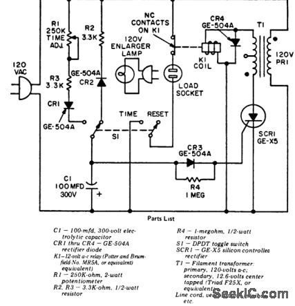
Enlarger phototimer (courtesy General Electric Company). (View)
View full Circuit Diagram | Comments | Reading(767)
SOFT_CLIPPER
Published:2009/7/21 21:34:00 Author:Jessie
Used after audio compressor to improve effective signal strength of SSB transmitter. Soft clipping is achieved by driving diode pair through resistance. Clipper is followed by low-noise FET voltage amplifier having broadband flat frequency response. Output filter sharply attenuates signals above about 3 kHz.-J,J,Schultz, Adding das to the Audio Compressor,73 Magazine, May 1974,p21-23and 25. (View)
View full Circuit Diagram | Comments | Reading(2040)
Basic_SCR_phase_control
Published:2009/7/21 21:31:00 Author:Jessie
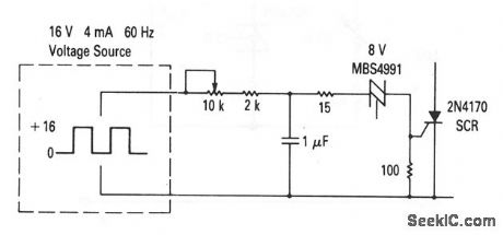
This circuit shows a basic phase-control scheme using an SCR and relaxation oscillator. The capacitor is charged through the resistor until the breakover voltage of the trigger (an SBS in this case) is reached. The SBS then changes to the on-state, and the capacitor is discharged through the SCR gate. Turn-on of the SCR is accomplished with a short, high-current pulse. In addition to an SBS, commonly-used triggers are UJTs, PUTs, optically coupled thyristors (chapter 9), and SIDACs. Phase control is obtained by varying the RC time constant of the charging circuit so that the trigger turn-on occurs at varying phase angles within a controlled half cycle. With the values shown, the conduction angle can be varied from about 20°to 150°. (View)
View full Circuit Diagram | Comments | Reading(1268)
| Pages:41/126 At 204142434445464748495051525354555657585960Under 20 |
Circuit Categories
power supply circuit
Amplifier Circuit
Basic Circuit
LED and Light Circuit
Sensor Circuit
Signal Processing
Electrical Equipment Circuit
Control Circuit
Remote Control Circuit
A/D-D/A Converter Circuit
Audio Circuit
Measuring and Test Circuit
Communication Circuit
Computer-Related Circuit
555 Circuit
Automotive Circuit
Repairing Circuit