
Electrical Equipment Circuit
Index 61
SCS_SHIFT_REGISTER
Published:2009/7/24 2:01:00 Author:Jessie
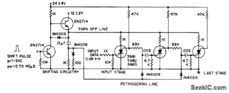
Shill pulse turns off all silicon controlled switches. Trailing edge of turnoff pulse is differentiated for turning on appropriate stages. 2N2714 will easily drive ten scs stages.- Transistor Manual, Seventh Edition, General Electric Co., 1964, p 432. (View)
View full Circuit Diagram | Comments | Reading(747)
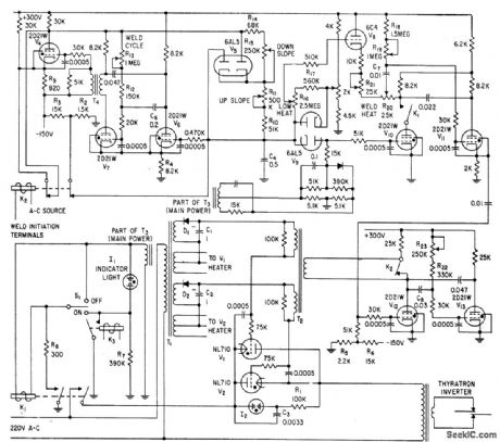
HEAVY_DUTY_WELDER_CONTROL
Published:2009/7/24 2:18:00 Author:Jessie

Flip-flop thyratron circuit makes pairs of ignitrons share load alternately, to prevent overloading of tubes when welder is used for heavier weld or for longer lime than originally intended.-J. Markus and V. Zeluff, Handbook of Industrial Electronic Control Circuits, McGraw-Hill, New York, 1956, p 342. (View)
View full Circuit Diagram | Comments | Reading(915)
HEAT_PROGRAM_TIMER
Published:2009/7/24 2:12:00 Author:Jessie
Controls weld energy for production-line welding of electron tubes and other small components. Functions controlled are low heat, weld heat, up-slope time, weld time, and down-slope time. Adjustable potentiometers permit changing each of these times.-A. V. Ronis, Heat Program Timer Controls Weld Energy, Electronics, 31:23, p 76-78. (View)
View full Circuit Diagram | Comments | Reading(764)
Single_cell_temperature_compensated_crystal_clock
Published:2009/7/24 2:11:00 Author:Jessie
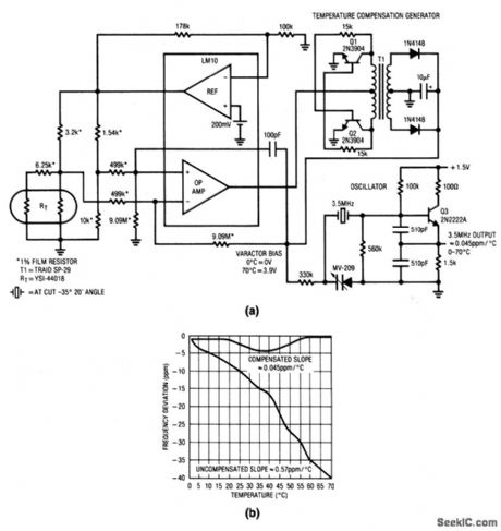
This 1.5-V oscillator provides a temperature-compensated output without the use of a current-consuming oven. Figure 8-15B shows the compensated-versus-uncompensated oscillator drift. Current consumption is 850 μA or less. The varactor diode tunes the oscillator frequency as the dc bias varies. An ambient-temperature-dependent bias is generated by the remaining circuitry. (View)
View full Circuit Diagram | Comments | Reading(1014)
SPOT_WELDING__TIMER
Published:2009/7/24 2:10:00 Author:Jessie
Five-thyratron sequence timer for resistance-type spot welder meets auto industry requirements for efficiency and reliability.-J. Markus and V. Zeluff, Handbook of Industrial Electronic Control Circuits, McGraw-Hill, New York,1956,p 343. (View)
View full Circuit Diagram | Comments | Reading(2481)
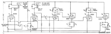
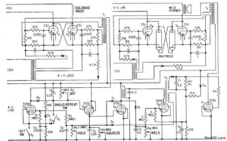
TIMER_FOR_RESISTANCE_WELDING_GUN
Published:2009/7/24 2:10:00 Author:Jessie
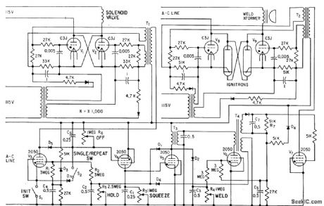
Provides exact timimg control for squeeze, weld, and hold, us well as fast repeat recycling, by control of thyratrons. Can be operated anywhere from single-shot to over 600 spots per minute. Timer is designed for fail-safe peration.-J. Markus, Handbook of Electronic Control Circuits, McGraw-Hill, New York, 1959, p 322. (View)
View full Circuit Diagram | Comments | Reading(861)
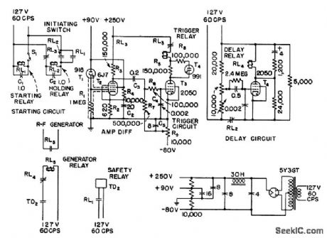
INDUSTRIAL_BRAZING_CIRCUIT
Published:2009/7/24 2:17:00 Author:Jessie
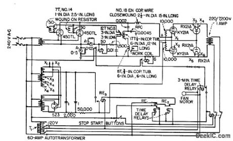
Applies high r-f power peaks in short-duration pulses, such as 11 kw for 2 sec or 45 kw for 0.5 sec, repeated every 5 sec. Settings of time delay relays RE1 and RE2 determine pulse lengths.-J. Markus and V. Zeluff, Handbook of Industrial Electronic Control Circuits, McGraw-Hill, New York, 1956, p 340. (View)
View full Circuit Diagram | Comments | Reading(766)
FOUR_FUNCTION__WELDING_TIMER
Published:2009/7/24 2:15:00 Author:Jessie
Thyratrons serve as relays for controlling squeeze time, weld time, hold time, and off time in high-speed resistance welding, Control Provides fail-safe operation, reduces transients by accurraely adjusting ignitron firing angle, and gives accurate repetition of timing cycle.-S. C. Rocka fellow, Electronic Control Times High-Speed Welding cycle,Electronics,31:33,p 70-73. (View)
View full Circuit Diagram | Comments | Reading(1355)
MODULATOR_CONTROL_FOR_FULL_WAVE_SCR_SWITCH
Published:2009/7/24 2:26:00 Author:Jessie
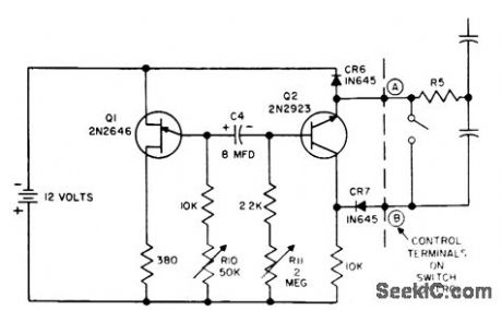
Used with high-power a-c scr switching circuit to provide regulation by varying ratio of full on cycles to full off cycles of supply voltage. Also suitable for oven and furnace temperature control, motor control, and flashers. With R10 at 10K, variaion of R11 from zero to maximum produced 40:1 load voltage swing.-F. W. Gutzwiller, RFI-Less Switching with SCRs, EEE, 12:3, p 51-53. (View)
View full Circuit Diagram | Comments | Reading(916)
PRECISION_WELD_INTERVAL_TIMER
Published:2009/7/24 2:21:00 Author:Jessie
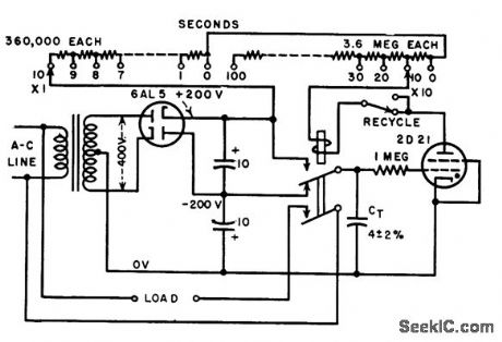
Stable timer provides intervals repetitive to accuracy of 0.75%, from 1 to 110 sec in 1-sec increments. Can be used for welder, enlarger, and other industrial controls.-J. Markus and V. Zeluff, Handbook of Industrial Electronic Control Circuits, McGraw-Hill, New York, 1956, p 292. (View)
View full Circuit Diagram | Comments | Reading(662)
PHOTOELECTRIC_WELD_MONITOR
Published:2009/7/24 2:23:00 Author:Jessie
Shuts off r-f generator automatically after copper lows when welding exhaust tubulation to metal vacuum tube. Light is refected by molten copper into phototube that initiates shutdown, with 0.6 sec delay introduced intentionally to allow copper to low around entire seal.-J. Markus and V. Zeluff, Handbook of Industrial Electronic Control Circuits, McGraw-Hill, New York, 1956, p 344. (View)
View full Circuit Diagram | Comments | Reading(1108)
10_MINUTE_STEPPED_SWEEP
Published:2009/7/24 2:59:00 Author:Jessie
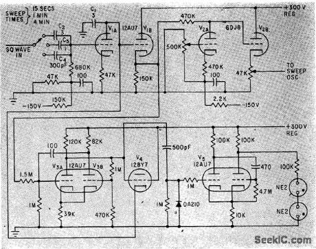
Provides long stepped sweeps required for swept-frequency ionosondes, with 100-v amplitude. Schmitt trigger V3 detects end of rundown and initiates recharging of C1.-K. Perry, Long Staircase Generator, Electronics, 35:35, p 54. (View)
View full Circuit Diagram | Comments | Reading(729)
NOISE_BLANKER
Published:2009/7/2 3:48:00 Author:May
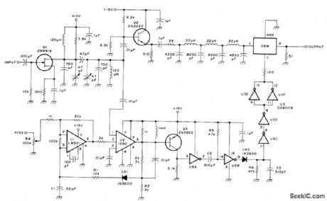
Minimizes effects of shortduration high-amplitude low-repetition-rate noise such as auto ignition noise, power-line arcing, and make-or-break switching. Developed for use in Collins ARR-41 receiver, where it is inserted between plate of second mixer and 500-kHz first IF amplifier. Q1 and its doubletuned drain circuit form low-gain bandpass amplifier that removes remaining local oscillator signal and sets bandwidth at about 50 kHz. Signal is then split into two channels. Q2 in main channel drives 50-ohm low-pass delay network with 700-kHz cutoff, feeding double-balanced mixer DBM operated as current-controlled attenuator. In other channel, noise amplifier U2 drives pulse detector Q3 and AGC detector CR1. Opamp U1 amplifies AGC and controls gain of U2. R4 is threshold adjustment. Gates U3B and U3C form mono used with gates of U3 to develop proper phase and current amplitude for operating blanking gate.-W. Stewart, Noise Blanker Design. Ham Radio. Nov. 1977. p 26-29. (View)
View full Circuit Diagram | Comments | Reading(3)
NEURON_SIMULATOR
Published:2009/7/24 2:39:00 Author:Jessie
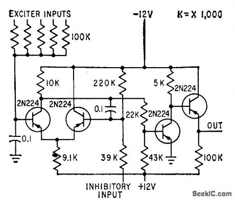
Simulates many of functions of eye and ear nerve cells. Output consists of 6.Mc pulses.-Artificial Neuron Uses Transistors, Electronics, 32:7, p 74. (View)
View full Circuit Diagram | Comments | Reading(1209)
Single_cell_undervoltage_indicator
Published:2009/7/24 2:37:00 Author:Jessie
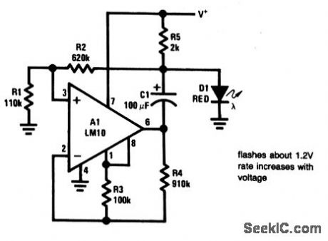
This circuit is essentially a voltage-controlled multivibrator that causes a red LED (D1) to flash. The flash rate is set by voltage from the single cell (about 1.4 sec-1 for 1.2 V, with a 300-μA drain, and 5.5 sec-1 at 1.55 V, with a 800-μA drain. To get an equivalent visibility with continuous operation would require more than 5-mA drain. (View)
View full Circuit Diagram | Comments | Reading(743)
LOAD_SIMULATOR
Published:2009/7/24 2:46:00 Author:Jessie
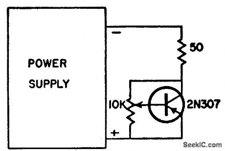
Is more economical than large rheostat when testing semiconductor power supplies for ripple attenuation and output impedance at different values of load current. Presents variable load to 30-V supply rated at 0.6 amp.-Inexpensive Load Simulator, Electronic Circuit Design Hond. book, Mactier Pub. Corp., N.Y., 1965 p 165. (View)
View full Circuit Diagram | Comments | Reading(1044)
Double_ended_voltage_monitor
Published:2009/7/24 2:44:00 Author:Jessie
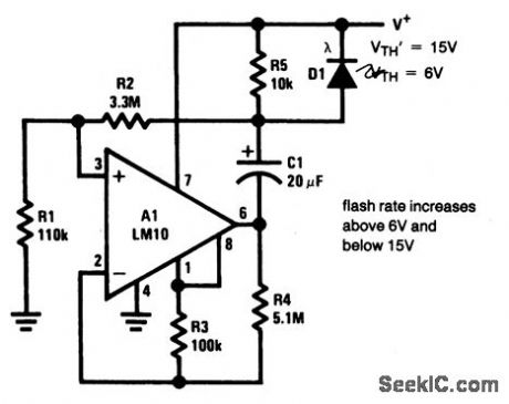


This circuit is similar to that of Fig. 8-26, except that the LED flash rate increases when the supply goes above 6 V, but below 15 V. The flash rate approaches zero near either limit. The minimum operating threshold is given by:
The maximum operating threshold is given by:
Typical circuit power drain is about 500 μA.
(View)
View full Circuit Diagram | Comments | Reading(1446)
ENLARGER_TIMER_STEP_CIRCUIT_0_TO_59_s
Published:2009/7/24 3:06:00 Author:Jessie
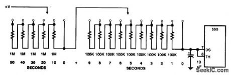
This circuit shows how to set up a NE555 timer to produce timing steps from 0 to 59 s in 1-s intervals. (View)
View full Circuit Diagram | Comments | Reading(774)
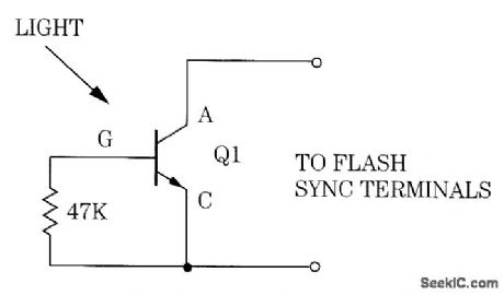
SIMPLE_SYNCHRONIZED_SLAVE_PHOTO_FLASH
Published:2009/7/24 3:04:00 Author:Jessie

A light-activated silicon-controlled rectifier (Q1) is triggered by a flash of light from the master flash unit. (View)
View full Circuit Diagram | Comments | Reading(762)
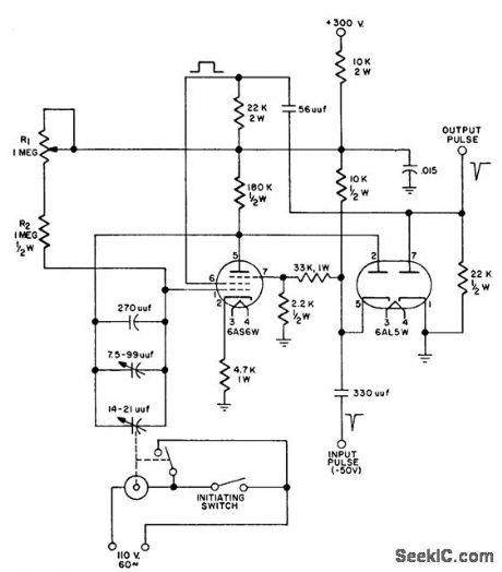
SEGMENTED_SWEEP_DISPLAY
Published:2009/7/24 3:03:00 Author:Jessie
Staircase voltage builds up across C2 when pulses from Q2 turn Q3 on momentarily. R3 controls voltage amplitude of each step. R1 controls rate of free-running oscillator tube.-J. E.Russell, Ten Signals at a Glance, Electronics, 37:19, p 54-57. (View)
View full Circuit Diagram | Comments | Reading(977)
| Pages:61/126 At 206162636465666768697071727374757677787980Under 20 |
Circuit Categories
power supply circuit
Amplifier Circuit
Basic Circuit
LED and Light Circuit
Sensor Circuit
Signal Processing
Electrical Equipment Circuit
Control Circuit
Remote Control Circuit
A/D-D/A Converter Circuit
Audio Circuit
Measuring and Test Circuit
Communication Circuit
Computer-Related Circuit
555 Circuit
Automotive Circuit
Repairing Circuit