
Electrical Equipment Circuit
Index 68
IC_precision_waveform_generator_with_variade_duty_cycle
Published:2009/7/25 4:21:00 Author:Jessie
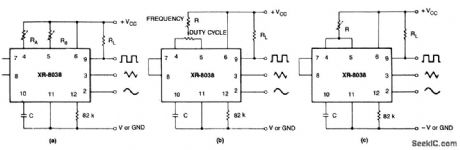
These circuits are similar to that of Fig 5-47,exceptfor alternate timing configurations and a duty-cycle control, If two separate timing resistors are used (Fig. 5-48A), the output frequency is: f= 0.3/RC, where RA= RB = R. If one timing resistor is used (Fig. 5-48B or 5-48C), the output frequency is: f =0.15/RC. If the duty cycle is to be varied over a small range, it should be centered around a duty cycle of 50%. (View)
View full Circuit Diagram | Comments | Reading(2106)
IC_precision_waveform_generator
Published:2009/7/25 4:19:00 Author:Jessie


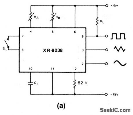


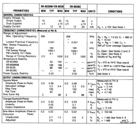
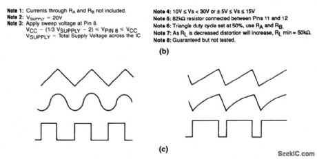
This circuit uses an XR-8038 to provide simultaneous sine, square, and triangle outputs, which can be sweep and frequency odulated,The frequency range is from 0.001 Hz to 200 kHz、with a variable duty cycle from 2%to 98% Electrical characteristics、and phase relationships of the outputs, are shown in Figs.5-47B and 5-47C,respectively.The operating frequency is set by capacitor C at pin 10,and the timing resistors at pins 4 and 5 See Conditions in Fig.5-47B. (View)
View full Circuit Diagram | Comments | Reading(1731)
_5_V_from_a_charge_pump_micropower
Published:2009/7/25 4:19:00 Author:Jessie
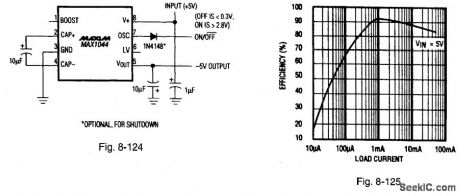
Figure 8-124 shows a MAX1044 charge pump connected to provide -5 V atmicropower. Figure 8-125 shows the efficiency curve.The input voltage range is 1.5 V to 10 V output impedance is 65 Ω quiescent current is 50 μA( VIN =5 V),maximum load current is 10 mA (VIN = 4.75 V) and shutdown current is 1.5 μA.This circuit is a scaled-down verslon of the Fig.8-122,The MAX1044 is basicallyidentical to the MAX660 except for a somew,hat higher input-voltage range, a 10-times-reduced output-current, and lower cost. The fixed-frequency oscillator range is 8 to 65 kHz.MAXIM BATTERY MANAGEMENT CIRCUIT COLLECTION, 1994, P. 61.
(View)
View full Circuit Diagram | Comments | Reading(758)
IC_precision_oscillator_with_a_split_supply
Published:2009/7/25 4:17:00 Author:Jessie
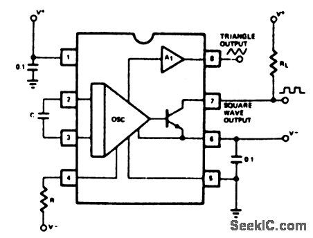
This circuit is similar to that of Fig. 5-44, except that the circuit requires a split supply greater than 7V, and simplifies the bias power connections at pins 5 and 6. Note that the triangle output has a +0.6-V offset when this circuit is used. (View)
View full Circuit Diagram | Comments | Reading(626)
IC_precision_oscillator_with_a_single_supply
Published:2009/7/25 4:16:00 Author:Jessie
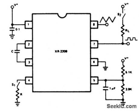
This circuit is similar to that of Fig. 5-44, except that a single supply isused. (View)
View full Circuit Diagram | Comments | Reading(1544)
Low_distortion_sine_wave_oscillator_1
Published:2009/7/25 3:31:00 Author:Jessie
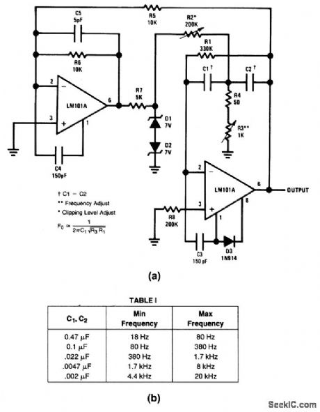
This circuit provides sine-wave outputs at frequencies shown in Fig.5-14B with low distortion (between 0.2% and 0.4% for 20% clipping, as set by R2).The frequency is set by R1, R3, and C1 as shown. (View)
View full Circuit Diagram | Comments | Reading(877)
Low_distortion_sine_wave_oscillator
Published:2009/7/25 3:12:00 Author:Jessie
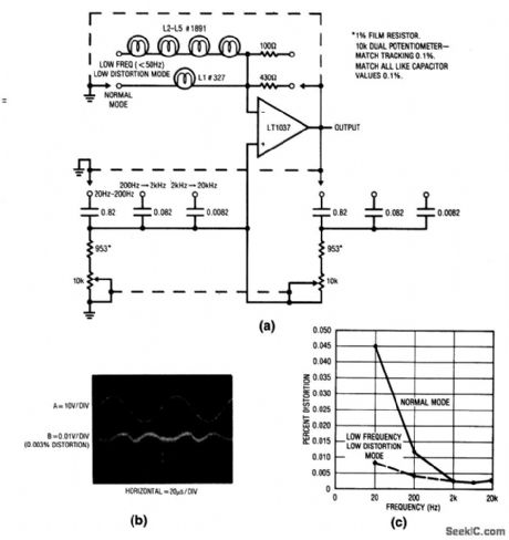
This circuit uses the positive temperature coefficient of lamp filaments in a modem adaptation of a classic oscillator circuit. A variable Wien bridge provides frequency tuning form 20 Hz to 20 kHz. Figure 5-1B shows the oscillator waveforms, while oscillator distortion versus is plotted in Fig. 5-1C. (View)
View full Circuit Diagram | Comments | Reading(2528)
Liquid measuring apparatus circuit diagram
Published:2011/8/1 3:02:00 Author:Ecco | Keyword: Liquid measuring apparatus
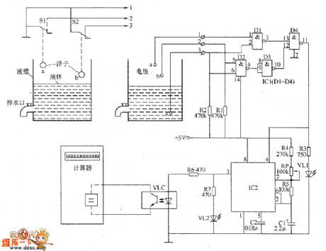
The liquid measuring apparatus circuit is composed of the liguid level control circuit, pulse generator and display circuit, and the circuit is shown as the chart. The pulse generator is composed of the time-base integrated circuit IC2, resistors R4 and R5, potentiometer RP and capacitors C1, C2. Display circuit is composed of the calculator, optocoupler VLC, LED VL2 and resistors R6, R7. R1 ~ R7 select the 1/4W metal film resistors or carbon film resistors. RP uses the organic solid potentiometer or variable resistor. C1 selects the aluminum electrolytic capacitor with the voltage in 16V.
(View)
View full Circuit Diagram | Comments | Reading(685)
Fixed_off_time_motor_control
Published:2009/7/25 0:18:00 Author:Jessie
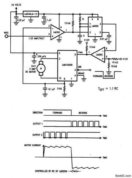
As shown by the waveforms in Fig. 3-31B, motor current modulates or dithers about a preset level, depending on the timer LM555 off-time (set by selection of R and C). The direction of motor rotation is set by the logic level at pin 3 of the LMD18200. (View)
View full Circuit Diagram | Comments | Reading(1013)
High_resolution_dithering_bar_graph_display
Published:2009/7/25 0:15:00 Author:Jessie
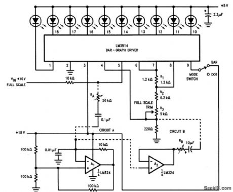
This circuit is an improved version of the Fig. 3-28 display, using a triangular-wave oscillator. With RA properly set, each incremental change in VIN can be detected because the glow from each LED can be made to spread gradually from one device to the next. If the signal-source impedance is high or not linear, false readings might occur. In this case, use CIRCUIT B to buffer the oscillator output. The display is most effective in the dot mode, where supply voltages can be brought up to 15 V. If bar mode is used, do not exceed +5 V on the LEDs (to avoid overheating). To trim, set the LM3914 output to full scale with R3. Then, adjust RA or RB so that when one LED is on, any small measured change of VIN will cause one of the adjacent LEDs to turn on. (View)
View full Circuit Diagram | Comments | Reading(911)
Dithering_bar_graph_display
Published:2009/7/25 0:13:00 Author:Jessie
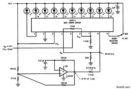
With this circuit, each of 10 LEDs has a fully on and a partially on mode, making 20 states discernible. This is accomplished by the LM324 (operating as a 1-kHz oscillator) driving a 60-mV pp signal into pin 8 of the LM3914.
(View)
View full Circuit Diagram | Comments | Reading(2928)
Precision_voltage_inverter
Published:2009/7/25 0:06:00 Author:Jessie
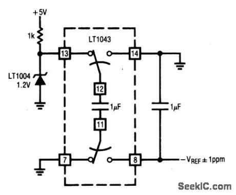
This circuit shows an LTC1043 (Fig. 1-4B) connected as a precision inverter. The circuit allows a reference to be inverted with 1 ppm accuracy. The circuit has high input impedance and requires no trimming. (View)
View full Circuit Diagram | Comments | Reading(0)
Timer_one_shot_monostable
Published:2009/7/25 0:03:00 Author:Jessie
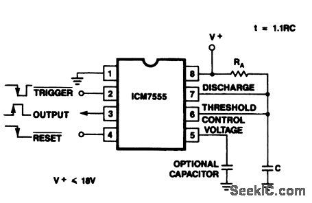
This circuit shows an ICM7555/56 timer connected as a one-shot or monostable multivibrator. The output time is determined by 1.1RAC. Use high values of R and low values of C for minimum current drain. At a supply of 4.5 V, this circuit will drive at least two TTL loads. The waveforms at pins 2, 3, and 4 show the relationships of the trigger, output and reset signals. (View)
View full Circuit Diagram | Comments | Reading(717)
Timer_multivibrator_with_adjustable_duty_cycle
Published:2009/7/25 0:01:00 Author:Jessie
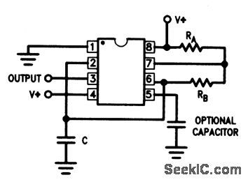
This circuit shows an ICM7555/56 timer connected as a free-running multivibrator, with an adjustable duty cycle, The frequency is determined by 1.44(RA + 2RD)C, while the duty cycle is set by RB/(RA + 2RB). Use high values of R and low values of C for minimum current drain. At a supply of 4.5 V, this circuit will drive at least two TTL loads. (View)
View full Circuit Diagram | Comments | Reading(868)
Easy_tune_sine_wave_oscillator
Published:2009/7/25 3:29:00 Author:Jessie
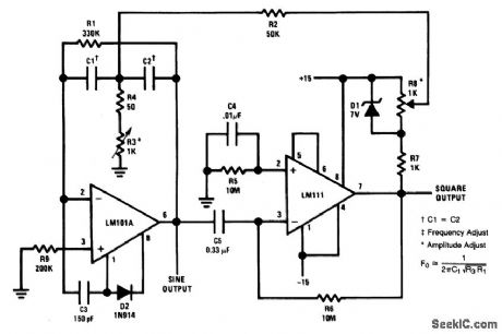
This circuit provides both sine- and square-wave outputs at frequencies from below 20 Hz to above 20 kHz, by varying R3. R8 sets amplitude.Distortion varies between 0.75% and 2% depending on R3 setting. The frequency range is set by R1, R3, and C1, as shown. (View)
View full Circuit Diagram | Comments | Reading(694)
1_Hz_to_1_MHz_sine_wave_VCO
Published:2009/7/25 3:27:00 Author:Jessie
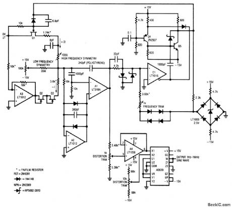
For a 0- to 10-V input, this circuit produces sine-wave outputs of 1 Hz to 1MHz, Both symmetry and distortion can be trimmed ndependently. (View)
View full Circuit Diagram | Comments | Reading(1135)
Low_frequency_sine_wave_generator
Published:2009/7/25 3:25:00 Author:Jessie
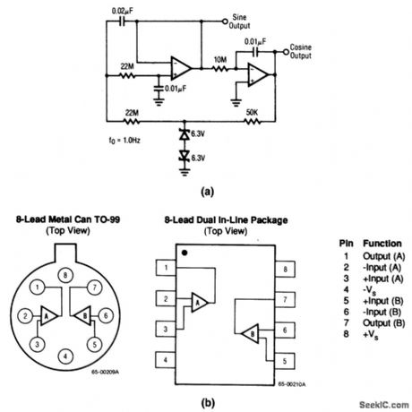
This circuit uses both sections of an RC4559 to form a 1-Hz sine-wave generator with both sine and cosine outputs. Figure 5-11B shows the pin connections. (View)
View full Circuit Diagram | Comments | Reading(0)
Triangle_and_square_wave_generator
Published:2009/7/25 3:24:00 Author:Jessie
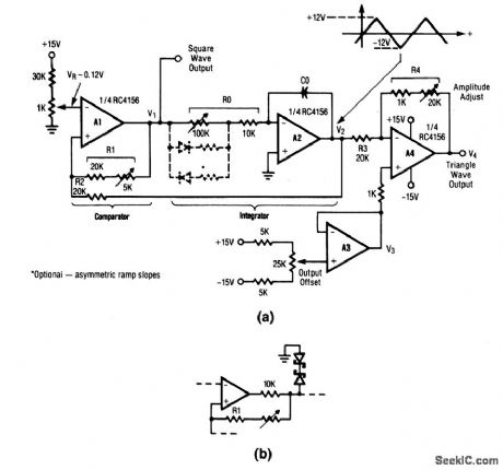
This circuit produces both triangle and square-wave outputs that can be adjusted independently. For best operation, set R1 and VR for a triangle at V2 with ±12-V amplitude. Then, adjust R4 for desired triangle output level. Triangle frequency is set by C0 and R0. Circuit should function well up to about 10 kHz. A more symmetrical waveform can be generated by adding a back-to-back Zener, as shown in Fig. 5-10B. (View)
View full Circuit Diagram | Comments | Reading(0)
Pulse_generator_astable_multivibrator
Published:2009/7/25 3:23:00 Author:Jessie
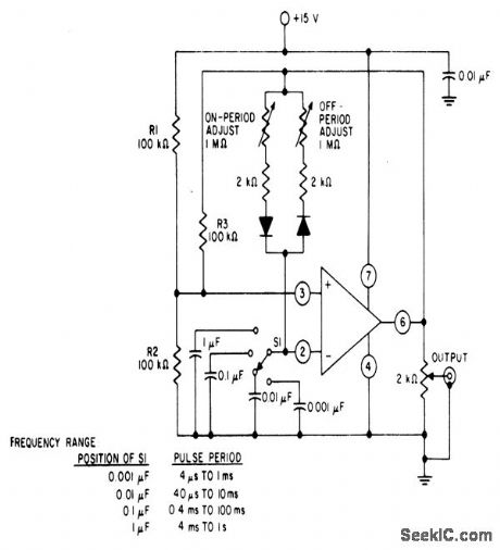
This circuit provides independent control of both On and Off periods, as well as the pulse period. (View)
View full Circuit Diagram | Comments | Reading(617)
Staircase_generator
Published:2009/7/25 3:22:00 Author:Jessie
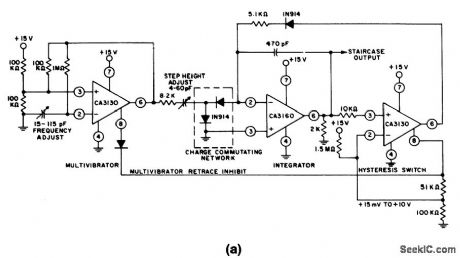
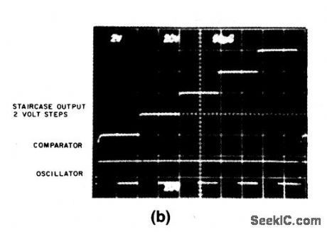
Both the frequency and step height can be adjusted separately in this circuit. Figure 5-8B shows the waveforms for each section. (View)
View full Circuit Diagram | Comments | Reading(0)
| Pages:68/126 At 206162636465666768697071727374757677787980Under 20 |
Circuit Categories
power supply circuit
Amplifier Circuit
Basic Circuit
LED and Light Circuit
Sensor Circuit
Signal Processing
Electrical Equipment Circuit
Control Circuit
Remote Control Circuit
A/D-D/A Converter Circuit
Audio Circuit
Measuring and Test Circuit
Communication Circuit
Computer-Related Circuit
555 Circuit
Automotive Circuit
Repairing Circuit