
Electrical Equipment Circuit
Index 64
Dual_high_side_switch_driver_with_extended_voltage_range
Published:2009/7/24 5:34:00 Author:Jessie
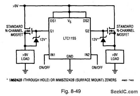
Figure 8-49 shows an LTC1155 connected as a switch driver for voltages greater than 9 V. The circuit is the same as that shown in Fig. 8-48, with the addition of the zeners. LINEAR TECHNOLOGY, APPLICATION NOTE 53, P. 2. (View)
View full Circuit Diagram | Comments | Reading(713)
Avalanche_pulse_generator_for_rise_fall_measurements
Published:2009/7/24 7:27:00 Author:Jessie
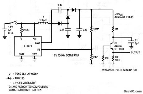
This circuit draws only about 5 mA from the 1.5-V battery, and produces a 10-V pulse with a typical rise and fall time of about 350 ps. Q1 might require selection to get the desired avalanche behavior. A sample of 50 Motorola 2N2369s, spread over a 12-year date-code span,yielded 82%(with some in the 220- to 230-ps range). All good 2N2369s switched in less than 650 ps. C1 is selected for a 10-V amplitude output. The value spread is typically 2 to 4 pF. Ground-plane construction with high-speed layout techniques are essential for good results from this circuit. Linear Technology Corporations 1991, AN47-93. (View)
View full Circuit Diagram | Comments | Reading(1812)
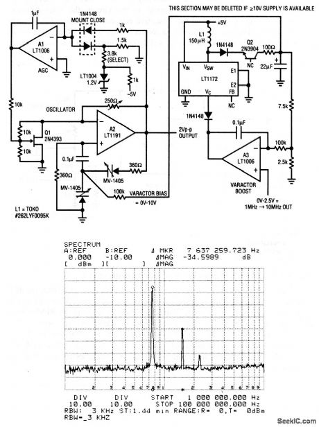
Varactor_tuned_Wien_bridge_oscillator
Published:2009/7/24 7:26:00 Author:Jessie
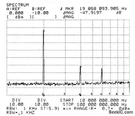
This circuit replaces the lamp (Fig. 5-18) and electronic control (Fig. 5-19) with a Wien network to produce a variable-frequency output from 1 to 10 MHz. Usually, Wien circuits require manually adjustable elements (dual pots or two-section variable capacitors) for tuning. In this circuit, the Wien-network resistors are fixed (360Ω), and the capacitive elements are accomplished with varactor diodes. The circuit is tuned by a control voltage at the noninverting input of A3. Figure 5-20B is a spectrum analysis of the oscillator output. Linear Technology corporation, 1991, AN47-51. (View)
View full Circuit Diagram | Comments | Reading(1140)
Quartz_stabilized_oscillator_with_electronic_gain_control
Published:2009/7/24 7:21:00 Author:Jessie
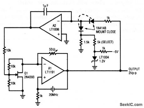
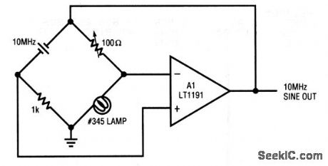
This circuit replaces the lamp(Fig. 5-18)with an electronic gain control or stabilization loop. To use this circuit, adjust the 50-Ω trimmer until 2-Vpp oscillations appear at the output of A1. Figure 5-19B is a spectrum analysis of the oscillator output. Linear Technology Corporation, 1991, AN47-50. (View)
View full Circuit Diagram | Comments | Reading(728)
Basic_quartz_stabilized_oscillator
Published:2009/7/24 7:17:00 Author:Jessie
This circuit uses a crystal within an amplifier's feedback path to create an oscillator. Although shown as 10 MHz, the circuit works well with a wide variety of crystal types over a 100-kHz to 20-MHz range. The use of a lamp to control amplifier gain is a classic technique that was first used in 1938. Linear Technology Corporation, 1991, AN47-49. (View)
View full Circuit Diagram | Comments | Reading(716)
Regenerative_sine_wave_converter
Published:2009/7/24 7:16:00 Author:Jessie
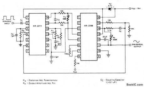
This circuit uses an XR-2211 PLL and an XR-2208 multiplier to form a universal sine-wave converter. The circuit converts any periodic input-signal waveform to a low-distortion sine-wave, the frequency of which is identical to the repetition rate of the input signal. The center frequency, fO, is determined by the values of CO and RO. With RO at 10 kΩ, as shown, the value of CO is determined by: CO(inμF)=100/fO in Hz. Notice that the XR-2211 VCO might not oscillate if RO is greater than 10 kΩ. The distortion and amplitude of the sine-wave output is adjusted by RX, and RF, as shown. EXAR Corporation Databook, 1990, p. 5-312. (View)
View full Circuit Diagram | Comments | Reading(3459)
Function_generator_with_wide_tuning_range
Published:2009/7/24 8:23:00 Author:Jessie
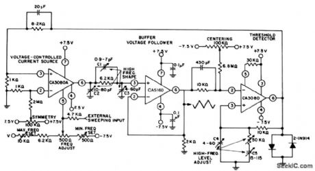
The adjustment range of this generator is in excess of 1,000,000/1, using a single frequency-adjust potentiometer. C1, C2, and C3 shape the triangular signal between 500 kHz and 1 MHz. C4, C5, and the 50-kΩ trimmer are adjusted to maintain essentially constant (±10%) amplitude up to 1 MHz. Harris Semiconductor, Linear and Telecom ICs, 1991, p. 3-224. (View)
View full Circuit Diagram | Comments | Reading(1076)
Pulse_generator_with_independent_on_and_off_periods
Published:2009/7/24 8:20:00 Author:Jessie
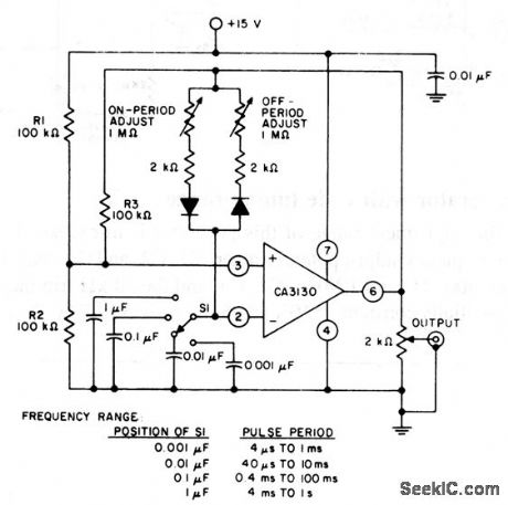
This circuit is a pulse generator or astable multivibrator, where the on and off periods can be adjusted separately. The pulse rate is selected by the setting of S1, and it remains essentially constant when the on-period and off-period resistors are adjusted. Harris Semiconductor, Linear and Telecom ICs,1991, p. 3-100. (View)
View full Circuit Diagram | Comments | Reading(808)
UJT_relaxation_oscillator
Published:2009/7/24 8:19:00 Author:Jessie
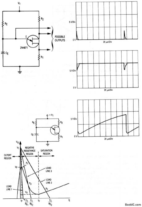
This figure shows the circuit, waveforms, and characteristics, where a UJT is used as a relaxation oscillator. This basic building block is used in most of the UJT timer and control circuits (described in chapter 9). The waveforms and characteristics are shown in Figs. 5-41B and 5-41C, respectively. The waveforms are those obtained when the circuit values are: RE=10 kΩ, CE= 0.01μF, R2=200Ω, R1=47Ω, and V1=20 V. The approximate period of the oscillator pulses can be found by:RECE×1.7. The value of RE must be such that the load line (Fig. 5-41C) intersects the emitter characteristic in the negative-resistance region. Motorola Thyristor Device Data, 1991, p .1-6-37, 38. (View)
View full Circuit Diagram | Comments | Reading(1985)
Relaxation_oscillator_using_a_SIDAC
Published:2009/7/24 8:17:00 Author:Jessie
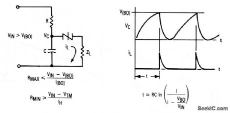
This figure shows the circuit and corresponding waveforms, where a SIDAC is used as a relaxation oscillator. Being a negative-resistance device, the SIDAC can be used as a simple relaxation oscillator, where frequency is determined primarily by the RC time constant. Once the capacitor voltage reaches the SIDAC breakover voltage V(BO), the SIDAC fires, and dumps the charged capacitor. Power can be obtained by placing the load in the discharge path. Such a circuit can be used as an xeon flasher (Fig. 8- l4). Motorola Thyristor Device Data, 1991, p. 1-4-6. (View)
View full Circuit Diagram | Comments | Reading(2084)
Low_frequency_precision_RC_oscillator
Published:2009/7/24 8:15:00 Author:Jessie
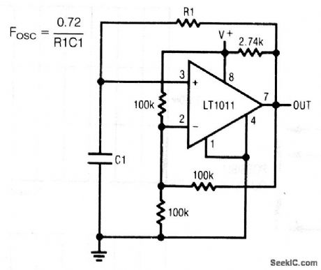
This circuit shows a precision RC oscillator, where the frequency is determined by the equation 0.72/(R1C1). The circuit is particularly useful for frequencies below 3 kHz. For a bipolar ±5-V output swing, refer the ground connection to -5 V. Linear Technology Corporation, Linear Appications Handbook, 1990, p. AN20-11. (View)
View full Circuit Diagram | Comments | Reading(998)
Crystal_oscillator_with_50_duty_cycle
Published:2009/7/24 8:14:00 Author:Jessie
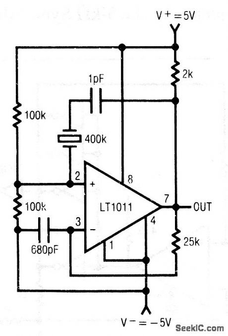
This circuit shows an LT1011 comparator biased in the linear mode and using a crystal to establish the resonant frequency. This circuit can achieve a temperature-independent clock up to a few hundred kHz. Linear Technology Corporaton, Linear Applications Handbook, 1990, p. AN20-12. (View)
View full Circuit Diagram | Comments | Reading(833)
Low_cost_oscillator_with_AT_cut_crystal
Published:2009/7/24 8:14:00 Author:Jessie
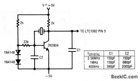
This circuit shows a crystal oscillator that is designed as a clock for an LTC1062 filter (chapter 7). The clock frequency is determined by the crystal and the values of C1 and C2, as shown by the table. Linear Technology Corporations Linear Applications Handbook, 1990, p. AN20-12. (View)
View full Circuit Diagram | Comments | Reading(749)
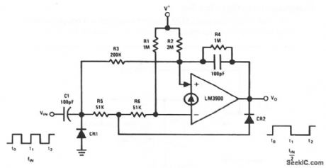
One_shot_multivibrator
Published:2009/7/24 9:09:00 Author:Jessie
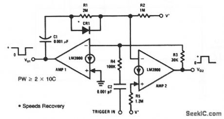
This circuit uses two LM3900 Norton amplifiers as a one-shot or monostable MV. CR1 can be a 1N914 or equivalent. National Semiconductor, Linear Applications Handbook, 1991, p. 242. (View)
View full Circuit Diagram | Comments | Reading(0)
Complementary_trigger_flip_flop
Published:2009/7/24 9:08:00 Author:Jessie
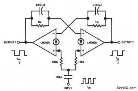
This circuit uses two LM3900 Norton amplifiers as a complementary flip-flop or as a divide-by-two configuration. National Semiconductor, Linear Applications Handbook, 1991, p. 241. (View)
View full Circuit Diagram | Comments | Reading(885)
Trigger_flip_flop
Published:2009/7/24 9:07:00 Author:Jessie
This circuit uses an LM3900 Norton amplifier as a trigger flip-flop as a divide-by-two configuration. CR1 and CR2 can be 1N914s or equivalent. National Semiconductor, Linear Applications Handbook, 1991, p. 241. (View)
View full Circuit Diagram | Comments | Reading(1703)
Bi_stable_multivibrator
Published:2009/7/24 9:06:00 Author:Jessie
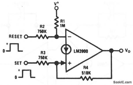
This circuit uses an LM3900 Norton amplifier as a bi-stable MV (or asynchronous RS flip-flop). A positive pulse at the Set input causes the output to go high (approximately V+), and a Reset positive pulse returns the output to essentially 0 V. National Semiconductor, Linear Applications Handbook, 1991, p. 240. (View)
View full Circuit Diagram | Comments | Reading(746)
Pulse_generator_1
Published:2009/7/24 9:05:00 Author:Jessie
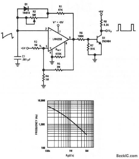
This circuit uses an LM4250 programmable op amp. Figure 5-55B shows the relationship between the pulse frequency and the setting of R2. The output of Q1 can interface directly with TTL/DTL circuits. National Semiconductor, Linear Applications Handbook, 1991, p. 208. (View)
View full Circuit Diagram | Comments | Reading(0)
Crystal_controlled_comparator_oscillator
Published:2009/7/24 9:04:00 Author:Jessie
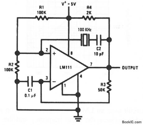
This circuit also uses an LM111 comparator to produce a 100-kHz output. The circuit is similar to that of Fig. 5-53, except that positive feedback is obtained through the crystal (operating in a series-resonant mode). The high input impedance of the comparator minimizes crystal loading and contributes to frequency stability. National Semiconductor, Linear Applications Handbook, 1991, p. 132. (View)
View full Circuit Diagram | Comments | Reading(1212)
Free_running_multivibrator
Published:2009/7/24 9:03:00 Author:Jessie
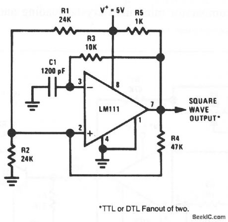
This circuit uses an LM111 comparator to produce a 100-kHz square-wave output. The frequency can be changed by varying C1, or by adjusting R1 through R4, while keeping the ratios constant. Because of the low input current of a comparator, large circuit impedances can be used. Thus, low frequencies can be obtained with relatively small capacitor values (compared to most op amp MVs). A1-Hz output requires a 1-μF capacitor. The speed of the comparator also permits operation above 100 kHz. National Semiconductor, Linear Applications Handbook, 1991, p. 132. (View)
View full Circuit Diagram | Comments | Reading(941)
| Pages:64/126 At 206162636465666768697071727374757677787980Under 20 |
Circuit Categories
power supply circuit
Amplifier Circuit
Basic Circuit
LED and Light Circuit
Sensor Circuit
Signal Processing
Electrical Equipment Circuit
Control Circuit
Remote Control Circuit
A/D-D/A Converter Circuit
Audio Circuit
Measuring and Test Circuit
Communication Circuit
Computer-Related Circuit
555 Circuit
Automotive Circuit
Repairing Circuit