
Electrical Equipment Circuit
Index 72
SOUND_LIGHT_FLASH_TRIGGER
Published:2009/6/28 20:55:00 Author:Jessie
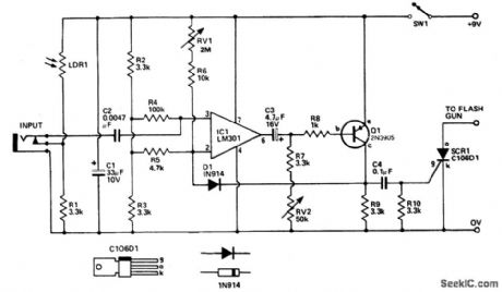
Sound input to the microphone triggers tthe IC monostable circuit which subsequently triggers an SCR, and hence the flash, after a time delay. This delay is adjustable—by varying the monostable on-time—from from 5 milliseconds to 200 milliseconds. (View)
View full Circuit Diagram | Comments | Reading(2370)
SINGLE_TRANSISTOR_PHASE_SHIFTER
Published:2009/6/28 20:40:00 Author:Jessie
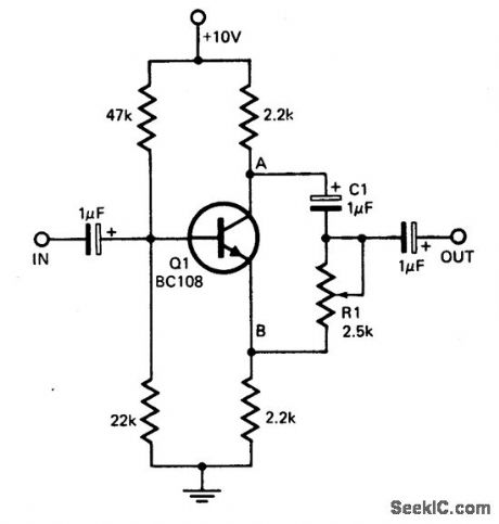
This circuit provides a simple means of obtaining phase shifts between zero and 170°.The transistor operates as a phase splitter, the output at point A being 180° out of phase with the input. Point B is in phase with the input phase. Adjusting R1 provides the sum of various proportions of these and hence a continuously variable phase shift is provided. The circuit operates well in the 600 Hz to 4 kHz range. (View)
View full Circuit Diagram | Comments | Reading(0)
PHASE_SEQUENCE_INDICATOR
Published:2009/6/28 20:39:00 Author:Jessie
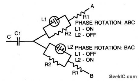
Simple, portable phase-sequence indicator determines the proper phase rotation in polyphase circuits. Major components are two neon lamps, two resistors, and a capacitor. In operation, the leg voltages are unbalanced, so that the lamp with the maximum voltage—or proper phase sequence—lights. Table shows typical component values for various circuit frequencies. (View)
View full Circuit Diagram | Comments | Reading(0)
ac_VOLTAGE_PROBE
Published:2009/6/26 5:32:00 Author:Jessie
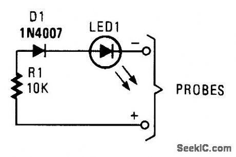
This simple probe can save your life by waming you of live circuitry. It's ideal for times when more than one person is working on a device. (View)
View full Circuit Diagram | Comments | Reading(0)
SIMPLE_VOLTAGE_PROBE
Published:2009/6/26 5:31:00 Author:Jessie
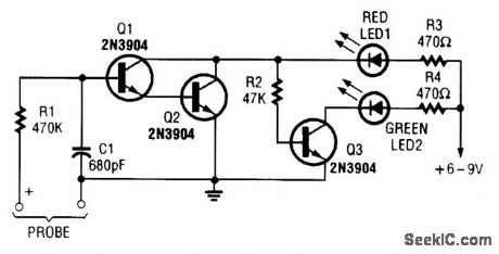
This simple voltage probe can be helpful in checking and troubleshooting solid-state circuitry. (View)
View full Circuit Diagram | Comments | Reading(0)
LOW_PARTS_COUNT_RATIOMETRIC_RESISTANCE_MEASUREMENT
Published:2009/6/26 4:04:00 Author:Jessie
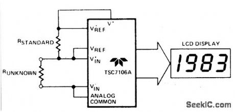
The unknown resistance is put in series with a known standard and a current passed through the pair. The voltage developed across the unknown is applied to the input and the voltage across the known resistor applied to the reference input. If the unknown equals the standard, the display will read 1000. The dis-played reading can be determined from the following expression:Runknown
Displayed Reading= ___________ =×1000 RstandardThe display will overrange for Runknown, ≥2× Rstandard. (View)
View full Circuit Diagram | Comments | Reading(1541)
VLF_CONVERTER
Published:2009/6/26 3:51:00 Author:Jessie
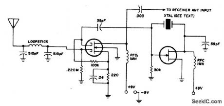
This converter uses a low-pass filter instead of the usual tuned circuit so the only tuning required is with the receiver. The dual-gate MOSFET and FET used in the mixer and oscillator aren't critical. Any crystal having a frequency compatible with the receiver tuning range may be used. For example, with a 3500 kHz crystal, 3500 kHz on the receiver dial corresponds to zero kHz; 3600 to 100 kHz; 3700 to 200 kHz, etc. (At 3500 khz on the receiver all one can hear is the converter os-cillator, and VLF signals start to come in about 20 kHz higher.) (View)
View full Circuit Diagram | Comments | Reading(1)
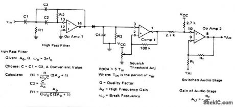
SQUELCH_CIRCUIT_FOR_AM_OR_FM
Published:2009/6/26 3:50:00 Author:Jessie
View full Circuit Diagram | Comments | Reading(1145)
TRANSMATCH
Published:2009/6/26 3:04:00 Author:Jessie
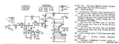
Tapped variable inductance and titree broadcast tuning capacitors are easily preadjusted to match low-power (QRP) transmitter to antenna for SWR of 1 in commonly used amateur bands. Resistance bridge is used only for initial determination of correct settings for C1, C2, C3, and S2 at each band to be used.Set S1 at n, feed peak output of transmitter to J1 (5 W maximum), and adjust R4 for full.scale frequency to be used. Repeat procedure with reading of M1. Next, conned 50.ohm resistive antenna or feed line in place of dummy load, load between CR1-R1 junction and ground. Meter reading should now drop to zero, indicating null at 50 ohms,Move 50-ohm dummy load to J2, set S1 at 2, and adjust seetings of C1,C2, and C3 for zero deflection of meter,Note settings, then repeat for each other transmitter frequency to be used. Repeat procedure with antenna or feed line in place of dummy load, After completing adjustments, set S1 to 3 to bypass bridge for normal transmitter opetation.-D. DeMaw, A Poor Ham's QRP Transmatch, QST, Oct. 1973, p 11,13. (View)
View full Circuit Diagram | Comments | Reading(2942)
LINEAR_VOLTAGE_RAMP_GENERATOR
Published:2009/6/26 3:03:00 Author:Jessie

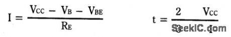
In the monostable mode, the resistor can be replaced by a constant current source to provide a linear ramp voltage. The capacitor still charges from 0 to 2/3 Vcc. The linear ramp time is given by the following equation:If VB is much larger than VBE, then t can be made independent of Vcc. (View)
View full Circuit Diagram | Comments | Reading(818)
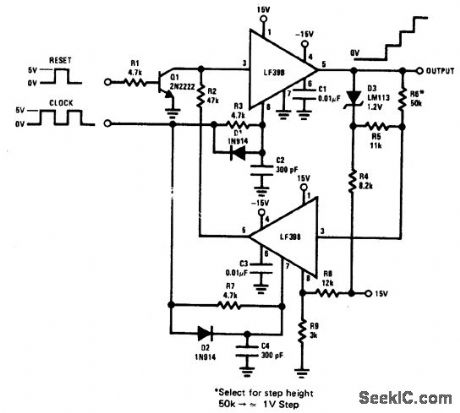
STAIRCASE_GENERATOR
Published:2009/6/26 3:01:00 Author:Jessie
View full Circuit Diagram | Comments | Reading(0)
LOGARITHMIC_WATTMETER
Published:2009/6/26 2:59:00 Author:Jessie
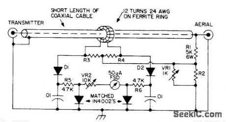
Single meter scale covers 1-1000W, with equally spaced divisions for 1,10,100,and 1000. This log scale makes it possible to measure very low reflected powers and very high forward powers simultaneously with same percentage accuracy.
Basis of operation is that voltage dropped across forward-biased 1N40C2 silicon PN junction diode is proportional to logarithm of cur rent through it. For 50-ohm line, use 220 for R2 and 27 for R3 and R4. For 75 ohm Iine, coffesponding values are 180 and 33. Detectordiodes are point-contact germanium rated at 80 PIV.
Article gives construction details. Ground coax braid at one end only. Ferrite ring is 0.5-inch Mullard FX1596 or equivalent.-P.G.Martin, Some Directional Wattmeters and a Novel SWR Meter, 73Magazine,Aug.1974,p 17,19-21,23-24,and 26. (View)
View full Circuit Diagram | Comments | Reading(3548)
FM_DEMODULAT0_R_AT_12_V__
Published:2009/6/25 23:28:00 Author:Jessie
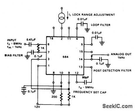
View full Circuit Diagram | Comments | Reading(1034)
80_METER_DIRECT_CONVERSION
Published:2009/6/25 23:28:00 Author:Jessie
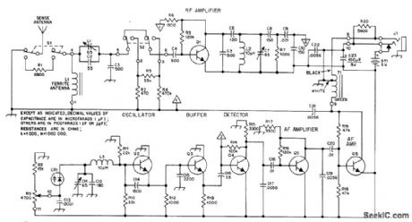
Portabl e receiver with directional ferrod antenna and ver-tical sense antenna was developed for radio foxhunting at 1975 Bov Scout World Jamboree in Norway, in competitions for locating four low-power crystal-controlled transmitters hid-den along 4-km course. Varactor-tuned oscillator provides 20-kHz tuning range with R9, ade-quate for the frequency used-3.566, 3.585, 3.635, or 3680 MHz. T1 is subminiature auto-transformer with 8-ohm and 2000-ohm sec-tions, for 8-ohm headphones. For high-imped-ance headphones, connect headphone jack J1 to lug 9 of T1. ON/OFF switch is not needed, L1 is 22 turns No. 28 enamel wound over two 10×95 mm ferrite rodstaped together. 01-06 are NPN high-frequency small-signal transistors.-N. K. Holter, Radio Foxhunting in Europe, QST, Nov. 1976, p 43-46. (View)
View full Circuit Diagram | Comments | Reading(1447)
5_STEP_ATTENUATOR
Published:2009/6/25 23:27:00 Author:Jessie

AppIication s indude comparing performance of various rece Mng an-tennas and measuring gain of preamp used abead of receiver. Dashed lines represent required shield partitions. All resistors are 1/4-W composition with 5% tolerance.-D.DeMaw, What Does My S-Meter Tell Me?, QST,June 1977,p 40-42. (View)
View full Circuit Diagram | Comments | Reading(1402)
RF_BRIDGE_FOR_COAX
Published:2009/6/25 23:27:00 Author:Jessie
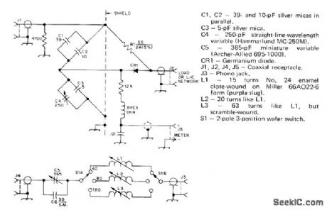
Simplifies adjustment of vertical antenna for 40, 80, and 160 meters.S1 in add-on LC unit switches coil for desited band. Values of C1-C4 and standard resistor R1 give range of 10 to 150 ohms for measurement of radiation resistance. Meter can be from 50 to 200μA full scale if 500 mW of power is available as signal source. For shorter-wavelength bands, change resistance in parallel with J1 to 5600 ohms and omit C6. L1 for 10 meters should then have 3 1/2 tums No. 18 spaced to occupy 1/4 inch on Miller4200 coilform. L2(15 meters) is Gtums No. 16 enamel closewound on similar form. L3 (20 meters) is 11 turns No.14 enamel on Miller 66A022-6 form.-J. Sevick, Simple RF Bridges, OST, April 1975, p 11-16 and 41. (View)
View full Circuit Diagram | Comments | Reading(1703)
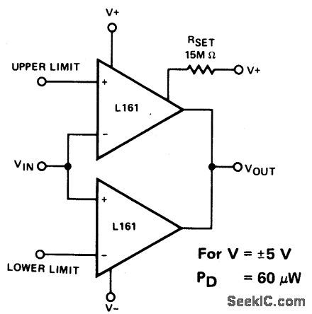
FM_DEMODULATOR_AT_5_V__
Published:2009/6/25 23:26:00 Author:Jessie
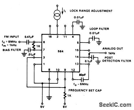
View full Circuit Diagram | Comments | Reading(1094)
DETECTOR_FOR__MAGNETIC_TRANSDUCER___
Published:2009/6/25 23:22:00 Author:Jessie
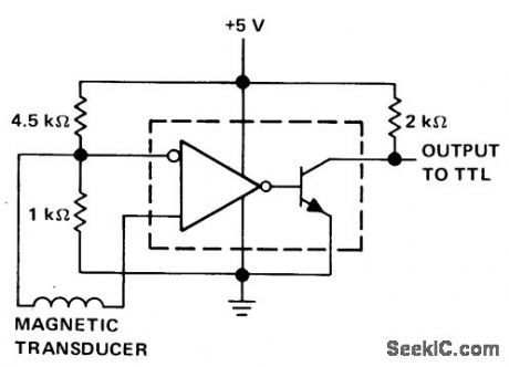
View full Circuit Diagram | Comments | Reading(1448)
SWR_COMPUTER
Published:2009/6/25 23:20:00 Author:Jessie
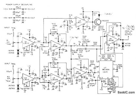
Au tomatlcally computos standing+ave ratio in 50-ohm coax feeding an tenna and delivers analog voltage for ddving meter or digital display. Inputs are forward (VFIN) and reverse (VRIN) voltages as convention-ally measured for SWR checks. Requires regu Iated ±15 VDC supply at 40 mA. Article gives construction details and covers adjustment of critical resistors during alignment.-T.May-hugh, A Digital SWR Computerl, 73 Magazine, Nov 1974, p 80-82,84, and 86. (View)
View full Circuit Diagram | Comments | Reading(1332)
SELF_EXCITED_SWR_BRlDGE
Published:2009/6/25 23:19:00 Author:Jessie
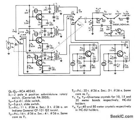
Portable bridge has built-in signal sources for each band from 80 through 10 meters, for tuning antenna on tower before transmission line is connected.Oscillators are crystal controlled at desired antenna tuneup frequencies. Separate oscillators for each band simplify switching problems, so only supply voltage from J1 and oscillator outputs to meter circuit need be switched. Current drain from 9-V battery is maximum of 12 mA.R17 and R18 should be closely matched, while R1, and R20 should have 5% tolerance.-T.P.Hulick, An S.W.R.Bridge with a Built-In 80 Through 10 Meter Signal Source, CQ1 June 1971,p 64-66 68, and 99. (View)
View full Circuit Diagram | Comments | Reading(1269)
| Pages:72/126 At 206162636465666768697071727374757677787980Under 20 |
Circuit Categories
power supply circuit
Amplifier Circuit
Basic Circuit
LED and Light Circuit
Sensor Circuit
Signal Processing
Electrical Equipment Circuit
Control Circuit
Remote Control Circuit
A/D-D/A Converter Circuit
Audio Circuit
Measuring and Test Circuit
Communication Circuit
Computer-Related Circuit
555 Circuit
Automotive Circuit
Repairing Circuit