
Electrical Equipment Circuit
Index 75
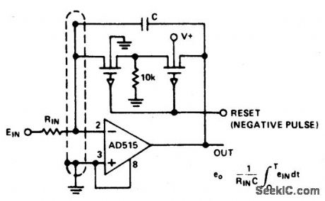
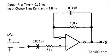
LOW_DRIFT_INTEGRQTOR_AND_LOW_LEAKAGE_GUARDED_RESET
Published:2009/6/25 21:27:00 Author:Jessie
View full Circuit Diagram | Comments | Reading(577)
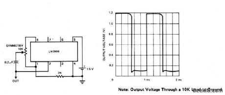
SQUARE_WAVE_OSCILLATOT
Published:2009/6/25 21:26:00 Author:Jessie
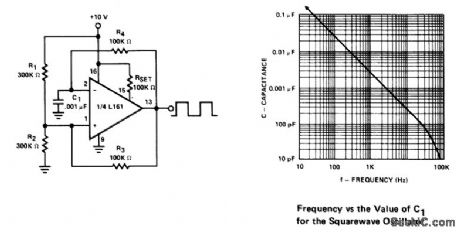
This generator is operable to over 100 kHz. The low frequency limit is determined by C1. Frequency is constant for supply voltages down to +5 V. (View)
View full Circuit Diagram | Comments | Reading(569)
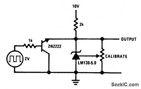
50_V_SQUARE_WAVE_CALLBRATOR
Published:2009/6/25 21:26:00 Author:Jessie
View full Circuit Diagram | Comments | Reading(509)
AIR_MOTION_DETECTOR
Published:2009/6/25 21:23:00 Author:Jessie
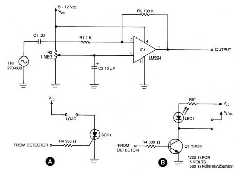
Circuit NotesSensing circuit detects either steady or fluctuating air flows. The heart of the circuit is a Radio Shack piezo buzzer (P/N 273-060) and an LM324 quad op amp. (Red wire from the piezo element connects to capacitor C1, and the black wire to ground.) When a current of air hits the piezo element, a small signal is gener-ated and is fed through C1 and RI to the in-verting input (pin 2) of one section of the LM324. That causes the output (pin 1) to go high. Resistor R3 adjusts sensitivity. The circuit can be made sensitive enough to detect the wave of a hand or the sensitivity can be set so low that blowing on the element hard will pro-duce no output. Resistor R2 is used to adjust the level of the output voltage at pin 1. The detector circuit can be used in various control applications. For example, an SCR can be used to control 117-volt AC loads as shown in A. Also, an NPN transistor, such as a TlP29, can be used to control loads as shown in B. (View)
View full Circuit Diagram | Comments | Reading(2486)
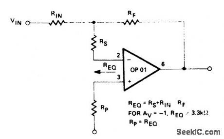
FAST_INVERTER_CIRCUIT
Published:2009/6/25 21:24:00 Author:Jessie
View full Circuit Diagram | Comments | Reading(579)
TTL_OSCILLATOR
Published:2009/6/25 21:23:00 Author:Jessie

TTL inverter stages, U1 and U2, are cross-connected with a crystal Y1. A resistor in each stage biases the normally digital gates into a region where they operate as amplifiers. Inverter stage U3 is used as a buffer. (View)
View full Circuit Diagram | Comments | Reading(782)
1_kHz_SQUARE_WAVE_OSCILLATOR
Published:2009/6/25 21:22:00 Author:Jessie
View full Circuit Diagram | Comments | Reading(1159)
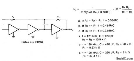
R_C_OSCILLATOR
Published:2009/6/25 21:21:00 Author:Jessie
View full Circuit Diagram | Comments | Reading(1235)
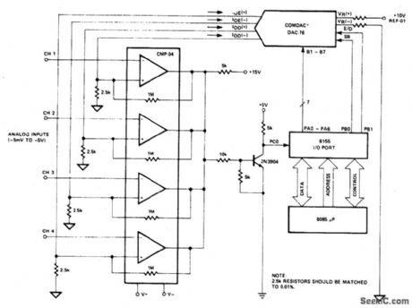
FOUR_CHANNEL_DATA_ACQUlSITION_SYSTEM
Published:2009/6/25 21:20:00 Author:Jessie
View full Circuit Diagram | Comments | Reading(1074)
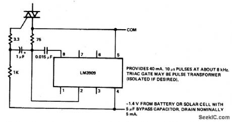
TRIAC_TRIGGER
Published:2009/6/25 21:21:00 Author:Jessie
View full Circuit Diagram | Comments | Reading(0)
POSITIVE_INPUT/NEGATIVE_OUTPUT_CHARGE_PUMP
Published:2009/6/25 21:12:00 Author:May

A simple means of generating a low-power voltage supply of opposite polarity from the main supply. Self oscillating driver produces pulses at a repetition frequency of 100 kHz.When the VMOS device is off, capacitor C is charged to the positive supply. When the VMOS transistor switches on, C delivers a negative voltage through the series diode to the output. The zener serves as a dissipative regulator. (View)
View full Circuit Diagram | Comments | Reading(1083)
POSITIVE_EDGE_DIFFERENTIATOR
Published:2009/6/25 21:19:00 Author:Jessie
View full Circuit Diagram | Comments | Reading(1072)
NEGATIVE_EDGE_DIFFERENTIATOR
Published:2009/6/25 21:16:00 Author:Jessie

View full Circuit Diagram | Comments | Reading(1165)
TAPE_RECORDER
Published:2009/6/25 21:15:00 Author:Jessie
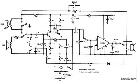
Complete record/playback cassette tape machine amplifier. Two of the transistors act as signal amplifiers, with the third used for automatic level control during the record mode. (View)
View full Circuit Diagram | Comments | Reading(1874)
SHIFT_REGISTER_DRIVER
Published:2009/6/25 21:14:00 Author:Jessie
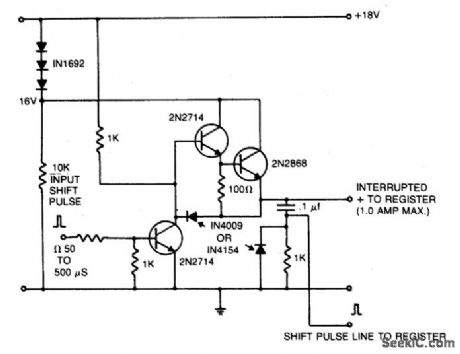
A 16 V power supply can be synthesized as shown using IN1692 rectifiers. A shift pulse input saturates the 2N2714 depriving the Darlington combination (2N2714 and 2N2868) of base drive. The negative pulse so generated on the 15 V line is differentiated to produce a positive trigger pulse at its trailing edge. (View)
View full Circuit Diagram | Comments | Reading(0)
MUSICAL_ENVELOPE_GENERATOR_AND_MODULATOR
Published:2009/6/25 21:00:00 Author:May
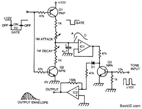
When a gate voltflge is applied, Q1 is turned on and capacitor C is charged via the attack pot in series with the 1 K resistor vary-ing this pot, attact time constant. A fast attack gives a percussive sound, a slow attack the affect of backward sounds. When the gate voltage returns to its off state, Q2 is turned on and capacitor is discharged via decay pot to ground. The envelope is buffered by IC1 and applied to Q3, which is used as a transistor chopper. A musical tone in the form of a squarewave is connected to the base of Q3.This turns the transistor on or off and thus the enve lope is chopped up at regular intervals, the intervals being determined by the pitch of the squarewave. The resultant waveform has the amplitude of the envelope and the harmonic structure of the squarewave. IC2 buffers the signal and D1 ensures that the envelope dies away at the end of a note. (View)
View full Circuit Diagram | Comments | Reading(2)
LASER_DIODE_PULSER
Published:2009/6/25 21:08:00 Author:Jessie
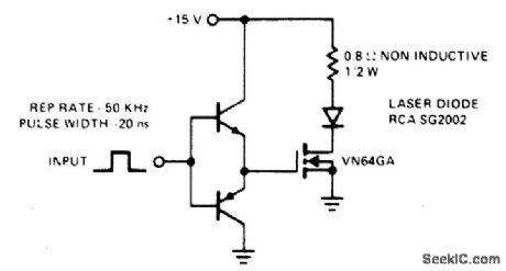
This drive is capable of driving the laser diode with 10 ampere, 20 ns pulses. For a 0.1% duty cycle, the repetition rate will be 50 kHz. A complementary emitter-follower is used as a driver. Switching speed is determined by the ft of the bipolar transistors used and the impedance of the drive source. (View)
View full Circuit Diagram | Comments | Reading(0)
INTERCOM
Published:2009/6/25 21:06:00 Author:Jessie
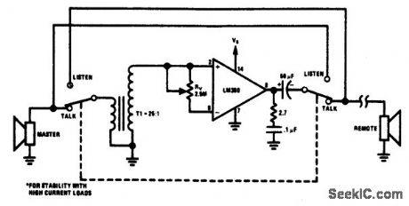
The circuit provides a minimum component intercom. With switch S1 in the talk position, the speaker of the master station acts as the microphone with the aid of stepup transformer T1. A turns ratio of 25 and a device gain of 50 allows a maximum loop gain of 1250. Rv provides a common mode volume control. Switching S1 to the listen position reverses the role of the master and remote speakers. (View)
View full Circuit Diagram | Comments | Reading(0)
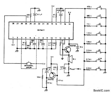
MUSICAL_ORGAN
Published:2009/6/25 21:07:00 Author:Jessie
View full Circuit Diagram | Comments | Reading(881)
MICROMETRONOME
Published:2009/6/25 21:04:00 Author:Jessie
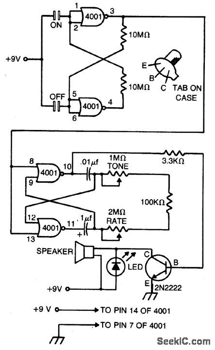
This compact metronome will run for years on a single nine-volt transistor battery.Has both tone and pulse rate controls, and uses touch plates to start and stop, can be built in a case no larger than a pack of cigarettes. The touch plates consist of two strips of metal about 1/16-inch apart mounted on, but insulated from, the case. Bridging the gap closes the switch. (View)
View full Circuit Diagram | Comments | Reading(1243)
| Pages:75/126 At 206162636465666768697071727374757677787980Under 20 |
Circuit Categories
power supply circuit
Amplifier Circuit
Basic Circuit
LED and Light Circuit
Sensor Circuit
Signal Processing
Electrical Equipment Circuit
Control Circuit
Remote Control Circuit
A/D-D/A Converter Circuit
Audio Circuit
Measuring and Test Circuit
Communication Circuit
Computer-Related Circuit
555 Circuit
Automotive Circuit
Repairing Circuit