
Electrical Equipment Circuit
Index 63
FREE_RUNNING_GROUNDED_GRID
Published:2009/7/24 3:41:00 Author:Jessie
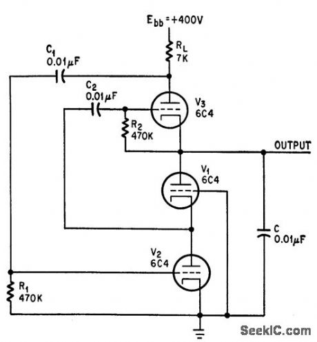
Has higher output impedance than other time-base sweep circuits. Reducing RL increases period.-C. Sing, Grounded-Grid Circuit Sweeps Better Than Miller or Bootstrap, Electronics, 38:6, p 83-84. (View)
View full Circuit Diagram | Comments | Reading(687)
FAST_RESET_SAWTOOTH
Published:2009/7/24 3:41:00 Author:Jessie
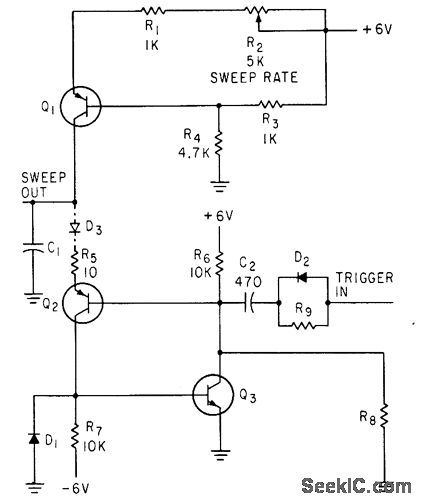
Regenerative pnp npn pctir in positive-feedback circuit Q1 is constant-current charging source for C1, with R2 varying charging rate and free-running frequency, which can range from 60 cps to 1 Mc.-N. C. Hekimian, PNP.NPN CIRCUITS: New Look at a Familiar Connection, Electronics, 35:47, p 42-46. (View)
View full Circuit Diagram | Comments | Reading(707)
DARLINGTON_WITH_BOOTSTRAP_FLIP_FLOP_SWEEP
Published:2009/7/24 3:40:00 Author:Jessie
Transistor Q3 in Darlington con nection improves linearity of controllable sweep comparable to vacuum-tube phantostron.-J. B. Payne III, Voltage-Controlled Bootstrap Generator, Electronics, 33:11, p 177-178. (View)
View full Circuit Diagram | Comments | Reading(864)
PHANTASTRAN
Published:2009/7/24 3:47:00 Author:Jessie
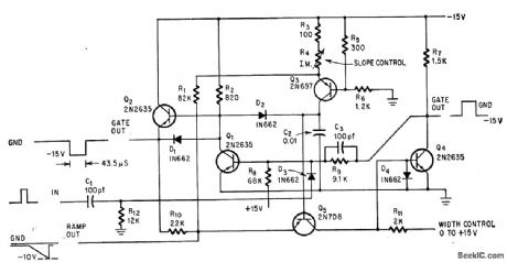
Transistorized version phantastron eliminates voltage pedestal by connecting C2 directly to ground. Slope is independent of gain of Q4 and is varied by R4 ove, range of 100 to 1. Duty cycle can be up to 98%. R4 is 1,000 ohms and width control voltage is 0.4 V for ramp output shown.-G. Marosi, Novel Sweep Circuit Eliminates Romp Pedestal, Electronics, 38:26, p 68. (View)
View full Circuit Diagram | Comments | Reading(863)
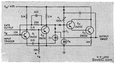
THREE_TRANSISTOR_PHANTASTRON
Published:2009/7/24 3:46:00 Author:Jessie
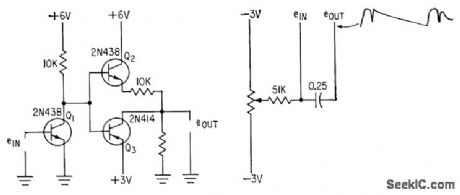
Use of both pnp and npn transistors gives desired current partition, while feedback required for sweep generator is provided by potentiometer arrangement at right.-N. C. Hekimian, Phantastron Circuits Using Transistors, Electronics, 34:8, p 46-47. (View)
View full Circuit Diagram | Comments | Reading(731)
SAWTOOTH_VOLTAGE_GENERATOR_MODULATES_KLYSTRON
Published:2009/7/24 3:45:00 Author:Jessie
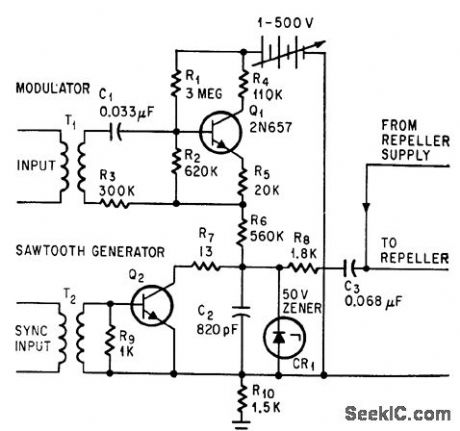
C2 is charged through R6 and discharged through Q2 operated in avalanche mode. Flyback time of sawtooth W.H. Chiles and H.G. Lafuse, Sweeping Carrier Signals Through Interference, Electronics, 37:16, p 94-96. (View)
View full Circuit Diagram | Comments | Reading(660)
SLOW_SWEEP
Published:2009/7/24 3:43:00 Author:Jessie
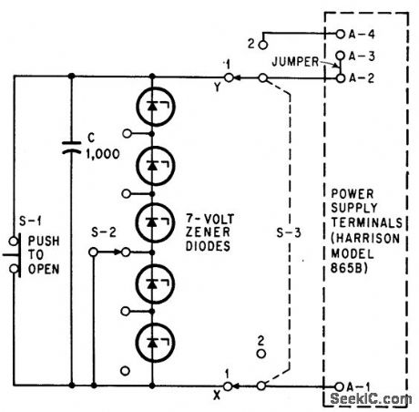
Large electrolytic capacitor and five zener diodes connected across standard transistor-regulated power supply give sweep voltage that increases 2 V per second, for classroom demonstrations.-M. H. Crothers, Added Capacitor Sweeps Power Supply, Electronics, 37:17, p 62. (View)
View full Circuit Diagram | Comments | Reading(641)
TWO_TRANSISTOR_PHANIASTRON
Published:2009/7/24 3:50:00 Author:Jessie
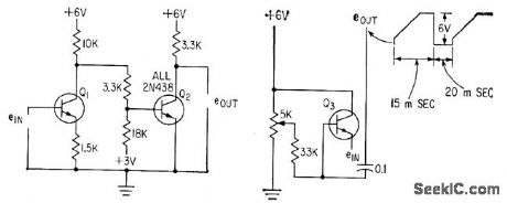
Q1 and Q2 simulate vacuum-tube phantastron sweep generator, Since input impedance is low, linearity con be improved by using emitter-follower Q3.-N. C. Hekimian, Phantastron Circuits Using Transistors, Electronics, 34:8, p 46-47. (View)
View full Circuit Diagram | Comments | Reading(797)
GCS_HORIZONTAL_SWEEP
Published:2009/7/24 3:50:00 Author:Jessie
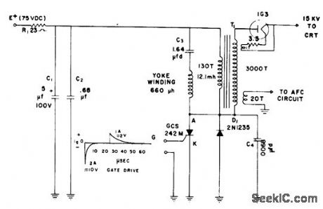
Uses gate-controlled switch GCS to replace horizontal output lube in television receiver, and semiconductor diode D1 to replace damper. GCS can cut off 2.5-amp peak current in 500 nsec.-J. W. Motto, Jr. GCS Sweep Circuit, EEE, 12:5, p 89-90. (View)
View full Circuit Diagram | Comments | Reading(1121)
Noninverting_comparator_with_hysteresis
Published:2009/7/24 4:21:00 Author:Jessie
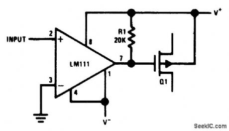
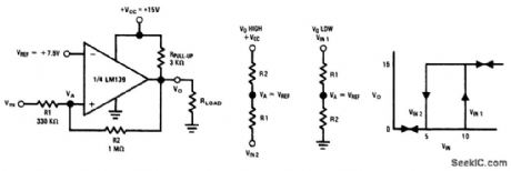
Fig. 15-6 This circuit is similar to that of Fig. 15-5, except that the output is noninverting. National Semiconductor Linear Applications Handbook 1991 p 259. (View)
View full Circuit Diagram | Comments | Reading(0)
Inverting_comparator_with_hysteresis
Published:2009/7/24 4:20:00 Author:Jessie
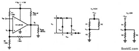
Fig. 15-5 This circuit provides positive feedback to force the comparator into a rapid state change when the input reaches the reference point. This overcomes one of the basic problems found in comparators (such as that in Fig. 15-1). Without feedback, the comparator can stay within the region between output high and low states (if the input is a slowly varying low-level signal). This might cause oscillation because a comparator is basically an uncompensated high-gain op amp. Only three resistors are required for feedback. The state changes are shown by the hysteresis graph. National Semiconductor Linear Applications Handbook 1991, p 258. (View)
View full Circuit Diagram | Comments | Reading(0)
Precision_level_detector_for_photodiode
Published:2009/7/24 4:19:00 Author:Jessie
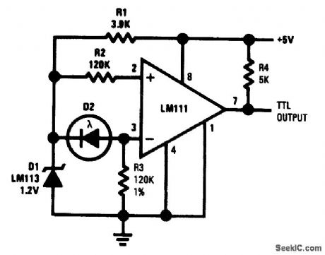
Fig. 15-4 This circuit is similar to that of Fig. 15-3, except that the Fig. 15-4 circuit is independent of supply voltage. D1 is a temperature- compensate d reference diode with a 1.23-V breakdown voltage. D1 acts as a regulator and delivers a stable voltage to the comparator. The circuit operates with a 5-V supply and is suitable for TTL. National Semiconductor, Linear Applications Handbook 1991 p, 130.
(View)
View full Circuit Diagram | Comments | Reading(866)
Zero_crossing_detector_for_squaring_a_sine_wave
Published:2009/7/24 4:31:00 Author:Jessie
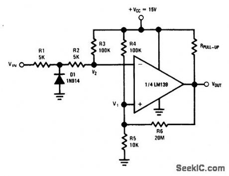
Fig. 15-15 This circuit symmetrically squares a sine wave (centered around 0 V) by introducing a small amount of positive feedback. Using the values shown, V1= V2 when VIN is zero. D1 ensures that the inverting input never goes below -100 mV and V2 never goes below ground. National Semiconductor Linear Applications Handbook 1991, p. 260. (View)
View full Circuit Diagram | Comments | Reading(1093)
Fast_window_detector
Published:2009/7/24 4:55:00 Author:Jessie
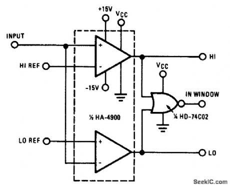
Fig. 15-35 Because of its speed, low offset current, and low offset voltage, this circuit is ideal for industrial-process system-feedback controllers or out-of-limit alarm indicators. The output indicates that the input is within the high-reference and low-reference window. Figures 15-32B and 15-32C show the pin connections and electrical characteristics, respectively. Harris Semiconductor Linear & Telecom ICs, 1991, p. 4-30. (View)
View full Circuit Diagram | Comments | Reading(770)
DIGITAL_DATA_READ_AMPLIFIER
Published:2009/7/24 4:53:00 Author:Jessie
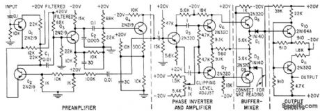
Presents 10,000-ohm input impedance to read head. No-signal input produces -4 V output; peak input as low as 1.35 my zero-to-peak produces +4 v output. Gives satisfactory reading at pulse repetition rates up to 22 kc.-R. F. Shaw, Universal Tope Amplifiers for Digital Data Systems, Electronics, 31:41, p 91-93. (View)
View full Circuit Diagram | Comments | Reading(653)
Comparator_logic_level_translator_CMOS_to_TTL
Published:2009/7/24 4:53:00 Author:Jessie
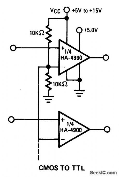
Fig. 15-33 This circuit is similar to that of Fig. 15-32, except that the interface is from CMOS to TTL. Harris Semiconductor linear & Telecom ICs 1991, p. 4-29. (View)
View full Circuit Diagram | Comments | Reading(882)
Timer_multivibrator
Published:2009/7/25 Author:Jessie
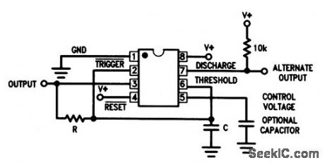
This circuit shows a general-purpose ICM7555/56 timer connected as a free-running multivibrator, with a true 50% duty-cycle output. The frequency is determined by 1.44/RC, with a maximum of about 1 MHz. Use high values of R and low values of C for minimum current drain. At a supply of 4.5 V, the circuit will drive at least two TTL loads. (View)
View full Circuit Diagram | Comments | Reading(751)
Basic_square_root_circuit
Published:2009/7/24 23:59:00 Author:Jessie
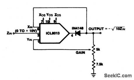
This circuit shows an ICL8013 (refer to Fig. 3-15) connected as a basic square root circuit. Use the following trim procedure.1. Connect the ICL8013 in the divider configuration (Fig. 3-16). 2. Adjust Zos, Yos, Xos, and gain using steps 1 through 6 of the divider trim procedure.3. Convert to the square-root configuration by connecting XIN to the output and inserting a diode between pin 4 and the output, as shown in Fig. 3-18.4. With ZIN =0 V adjust Zos for zero output voltage.
.
(View)
View full Circuit Diagram | Comments | Reading(796)
Dual_high_side_switch_driver
Published:2009/7/24 5:33:00 Author:Jessie
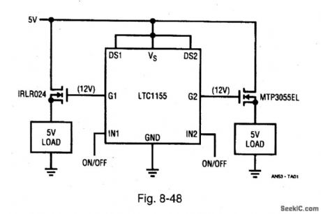
Figure 8-48 shows an LTC1155 connected as a high-side MOSFET switch driver (Chapter 2). The circuit generate 12-V from a 5-V supply to fully enhance (switch) logic-level N-channel MOSFET switches, with no external components required. The supply current is typically 85 μA with the switch fully enhanced, and 8 μA with the LTC1155 in standby (both inputs off). This combination of a low-drop N-channel MOSFET switch and micropower driver is an efficient means of controlling power in complex loads. Switch efficiencies in the 99% range are practical. LINEAR TECHNOLOGY, APPUCAnON NOTE 53, p. 1. (View)
View full Circuit Diagram | Comments | Reading(1496)
Slew_rate_reduction_for_high_crryoacity_loads
Published:2009/7/24 5:36:00 Author:Jessie

Figure 8-50 shows a method for reducing the slew rate in the circuits of Figs. 8-48 and 8-49. Supply circuits in battery-operated equipment are often bypassed with large capacitors to reduce transients. If not properly switched, such filter capacitors can produce glitches at start-up. For example, the 100-μF load capacitance shown could easily produce a start-up current of 10 A (well beyond the capability of the regulator), and possibly prevent start-up. The circuit of Fig. 8-50 reduces start-up current to about 15 mA. LINEAR TECHNOLOGY, APPLICATION NorE 53, P. 3. (View)
View full Circuit Diagram | Comments | Reading(757)
| Pages:63/126 At 206162636465666768697071727374757677787980Under 20 |
Circuit Categories
power supply circuit
Amplifier Circuit
Basic Circuit
LED and Light Circuit
Sensor Circuit
Signal Processing
Electrical Equipment Circuit
Control Circuit
Remote Control Circuit
A/D-D/A Converter Circuit
Audio Circuit
Measuring and Test Circuit
Communication Circuit
Computer-Related Circuit
555 Circuit
Automotive Circuit
Repairing Circuit