
Electrical Equipment Circuit
Index 73
DOUBLE_ENDED_LIMIT_DETECTOR
Published:2009/6/25 23:04:00 Author:Jessie
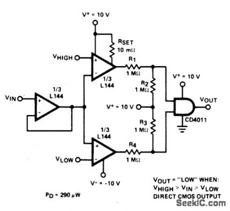
Circuit NotesDetector uses three sections of an L144 and a CM0S NAND gate to make a very low power voltage monitor. The 1 MO resistors R1, R2, R3, and R4 translate the bipolar t10 V swing of the op amps to a 0 to 10 V swing acceptable to the ground-referenced CMOS logic. The total power dissipation is 290 ptW while in limit and 330 ;tW while out of limit. (View)
View full Circuit Diagram | Comments | Reading(0)
DVM_FOR_SWR
Published:2009/6/25 23:00:00 Author:Jessie
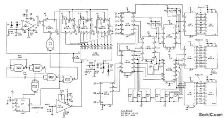


Converts voltage output from analog computer to drive for 3-digit LED display of standing-wave ratio. Circuit uses Precision Monolithics D/A converter AIMDAC-100CC-Q1.Requires regulated 5-VDC logic supply at 1A for digital display, along with ±15V supplies for logic. Article gives alignment procedure. Accuracy of digital reading is better than 0.1% over 0-8 V range.-T.Mayhugh, The Automatic SWR Computer, 73Magazine, Dec.1974, p 86-87 (View)
View full Circuit Diagram | Comments | Reading(929)
ANTENNA_ROTATOR
Published:2009/6/25 22:59:00 Author:Jessie
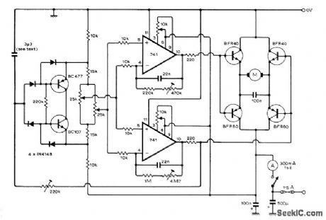
Two-opamp Wheatstone bridge provides positive and negative error signals to give proportional control for 24-VDC motor used for remote positioning of an tenna. Circuit will operate with supply ranging from 15 to 28 VDC. Off set null controls for opamps use 10K pots. Article describes opera-tion and adjustment of circuit in detail, -D.J.Telfer, An Aerial Rotator Servo, Wireless World, April1975, p 177-181. (View)
View full Circuit Diagram | Comments | Reading(1860)
LADDER_ATTENUATOR
Published:2009/6/25 22:51:00 Author:Jessie
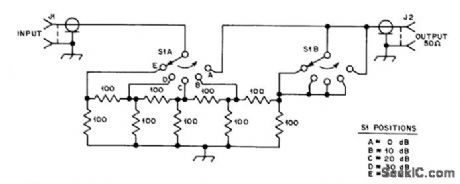
Inserted in series with receiving antenna to provide 5 steps of attenuation for comparing performance of anten-nas or preamps. Resistors are 1/4-W composition with 5% tolerance.-D. DeMaw, What Does My S-Meter Tell Me?, QST, June 1977, p 40-42. (View)
View full Circuit Diagram | Comments | Reading(1475)
DELAYED_BRAKE
Published:2009/6/25 22:48:00 Author:Jessie
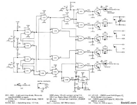
Protects antenna rotator on high tower from damage by delaying brake ac-tion automatically after rotation and by disa-bling direction-selector switches so antenna system coasts to stop before rotation can begin in other direction. For about 3.s delay in timer U4, use 2.2 megohms for R and 1μF for C instead of values shown. RV1 is commonly listed as V150LA20A by GE.S3-S5 are original brake release and direction switches in CDE Hamllrotor system,Article coners construction and installation, including modifications needed Incontrol unit.-A.B,White,A Delayed Brake Release for the Ham-ll,QST, Aug.1977、p14- 16 (View)
View full Circuit Diagram | Comments | Reading(1515)
ELECTRONIC_PHONE_BELL
Published:2009/6/25 22:40:00 Author:May
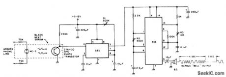
The speaker emits a distinctive warble tone when ring pulses are applied to the phone line. Use this circuit as a remote bell or discon-nect the phone's ringer for direct use. R1 ad-justs the duration of the output; R2 and R3 control the tone's duty cycle and frequency. The transistor is a general-purpose NPN photodevice. The neon bulb and transistor are coupled with the heat-shrink tubing to form an optoisolator. (View)
View full Circuit Diagram | Comments | Reading(865)
TELEPHONE_RINGER_USES_PIEZOELECTRIC_DEVICE
Published:2009/6/25 22:39:00 Author:May
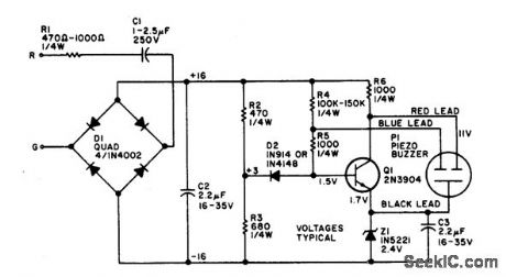
The electronic bell needs no power sup-ply. Most of the resistors are not critical, al-though C2, R2, and R3 work best at the values given. Leaving out RI will make the unit ring louder. The piezo buzzer may vary from store to store. If it has two leads, connect the red lead to the collector and the black lead to the emit-ter of Q1. If a third (blue) lead is present, connect it to the base of Q1. (View)
View full Circuit Diagram | Comments | Reading(873)
AUTOPATCH_TELEPHONE_LINE_INTERFACE
Published:2009/6/25 22:38:00 Author:May
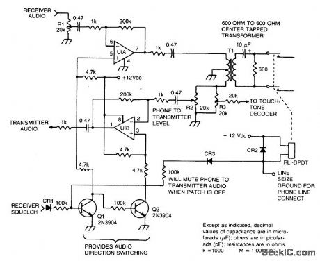
This circuit provides for the receiver-to-phone line and phone line-to-transmitter link, with both using an op amp for gain. (View)
View full Circuit Diagram | Comments | Reading(1847)
PHONE_AUTO_ANSWER_AND_RING_INDICATOR
Published:2009/6/25 22:37:00 Author:May

Ring detect circuit for automatic phone answering or tone generation for reverse autopatch use. (View)
View full Circuit Diagram | Comments | Reading(1420)
LOW_LINE_LOADING_RING_DETECTOR
Published:2009/6/25 22:36:00 Author:May

Low line current loading is provided by the H11BX522 photodarlington op-tocoupler, which provides a 1 mA output from a 0.5 mA input. (View)
View full Circuit Diagram | Comments | Reading(686)
TELEPHONE_HANDSET_TONE_DIAL_ENCODER
Published:2009/6/25 22:35:00 Author:May


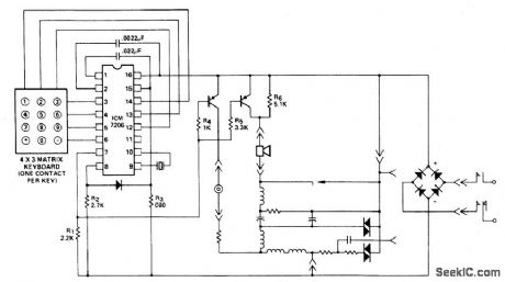
This encoder uses a single contact per key keyboard and provides all other switching func-tion electronically. The diode between termi-nals 8 and 15 prevents the output going more than 1 volt negative tive supply V-. The supply voltage range with respect to the nega-circuit operates over the from 3.5 volts to 15 volts. (View)
View full Circuit Diagram | Comments | Reading(932)
AUTOMATIC_PLANT_WATERER
Published:2009/6/25 22:35:00 Author:Jessie
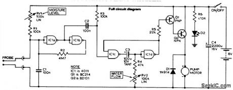
The unit consists of a sensor, timer, and electric water pump. The sensor is embedded in the soil, and when dry, the electronics operate the water pump for a preset time. The circuit is composed of a level sensitive Schmitt trigger, variable time monostable, and output driver. When the resistance across the probe increases beyond a set value (i.e., the soil dries), the Schmitt is triggered. C2 feeds a negative going pulse to the monostable when the Schmitt triggers and R2 acts as feedback, to ensure a fast switching action. (View)
View full Circuit Diagram | Comments | Reading(2080)
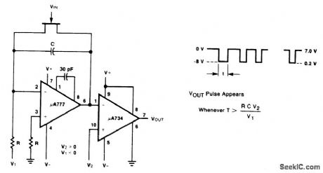
PULSE_WIDTH_DISCRIMINATOR
Published:2009/6/25 22:34:00 Author:Jessie
View full Circuit Diagram | Comments | Reading(0)
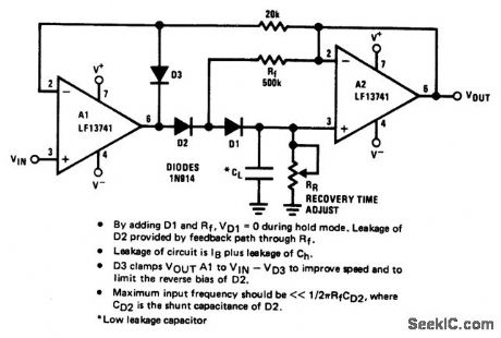
ULTRA_LOW_DRIFT_PEAK_DETECTOR
Published:2009/6/25 22:33:00 Author:Jessie
View full Circuit Diagram | Comments | Reading(2170)
MOISTURE_DETECTOR
Published:2009/6/25 22:32:00 Author:Jessie
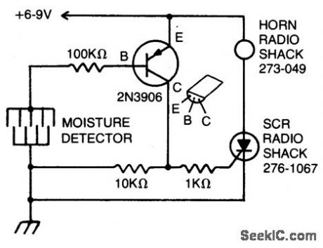
The detector is made of fine wires spaced about one or two inches apart. When the area between a pair of wires becomes moistened, the horn will sound. To turn it off, dc power must be disconnected. (View)
View full Circuit Diagram | Comments | Reading(0)
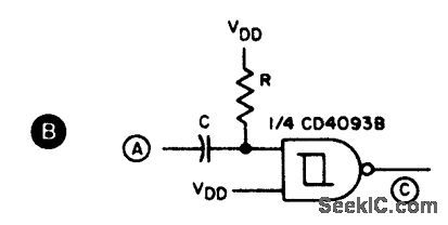
EDGE_DETECTOR
Published:2009/6/25 22:31:00 Author:Jessie
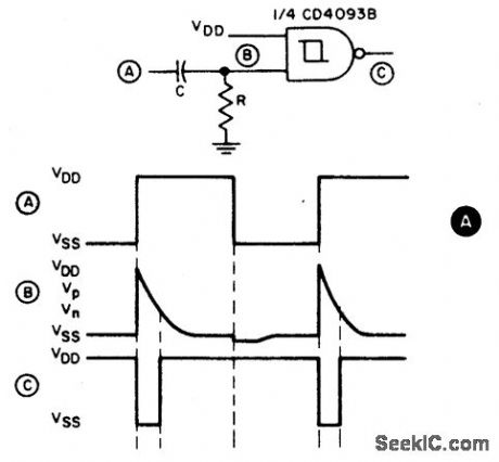
Circuit Notes
This circuit provides a short negativegoing output pulse for every positive-going edge at the input. The input waveform is coupled to the input by capacitor C; the pulse O length denends, as before, on R and C. If a negattve gomg edge detector is required, the circuit in B should be used. (View)
View full Circuit Diagram | Comments | Reading(5146)
PRECISION_PEAK_VOLTAGE_DETECTOR_WITH_A_LONG_MEMORY_TIME
Published:2009/6/25 22:29:00 Author:Jessie


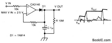
Circuit Notes
The circuit has negative feedback only for positive signals. The inverting input can only get some feedback when diode Dl is forward biased and only occurs when the input is posi-tive. With a positive input signal, the output of the op amp rises until the inverting input signal reaches the same potential. In so doing, the capacitor C is also charged to this potential.When the input goes negative, the diode Dl becomes reverse biased, the voltage on the capacitor remains, being slowly discharged by the op amp input bias current of 10 pico amps.Thus the discharge of the capacitor is domin-antly controlled by the resistor R, giving a time constant of 10 seconds. Thus, the circuit de-tects the most positive peak voltage and remembers it. (View)
View full Circuit Diagram | Comments | Reading(2060)
TELEPHONE_OFF_HOOk_INDICATOR
Published:2009/6/25 22:27:00 Author:Jessie
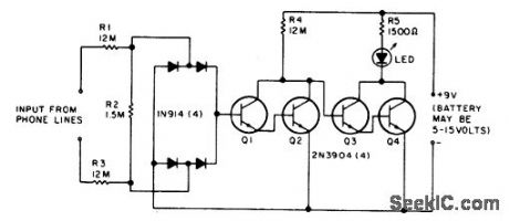
The LED flickers when the phone is ringing or being dialed. It glows steadily when the phone is off the hook. (View)
View full Circuit Diagram | Comments | Reading(0)
TV_MODULATOR_USING_A_MOTOROLA_MC1374
Published:2009/6/25 22:13:00 Author:May
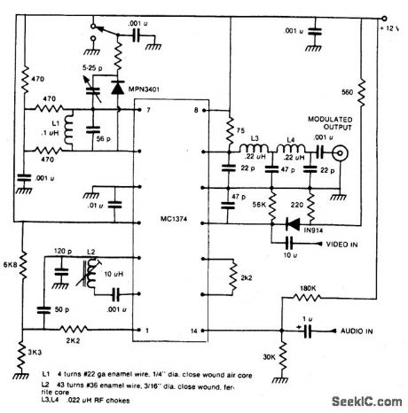
This one-chip modulator requires some outboard circuitry and a shielded box. (View)
View full Circuit Diagram | Comments | Reading(1261)
TELEPHONE_LINE_MONITOR
Published:2009/6/25 22:06:00 Author:May
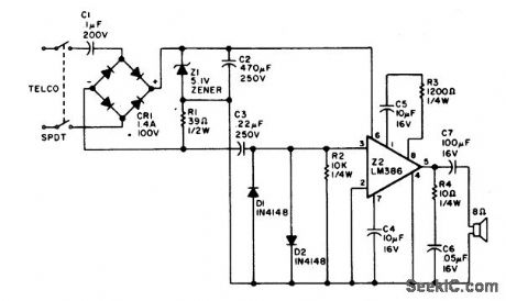
Using rectified audio as a power supply, this monitor will send the telephone line audio into an 8 ohm speaker. (View)
View full Circuit Diagram | Comments | Reading(132)
| Pages:73/126 At 206162636465666768697071727374757677787980Under 20 |
Circuit Categories
power supply circuit
Amplifier Circuit
Basic Circuit
LED and Light Circuit
Sensor Circuit
Signal Processing
Electrical Equipment Circuit
Control Circuit
Remote Control Circuit
A/D-D/A Converter Circuit
Audio Circuit
Measuring and Test Circuit
Communication Circuit
Computer-Related Circuit
555 Circuit
Automotive Circuit
Repairing Circuit