
Electrical Equipment Circuit
Index 40
THERMOELECTRIC_COOLING_CONTROL
Published:2009/7/21 21:22:00 Author:Jessie
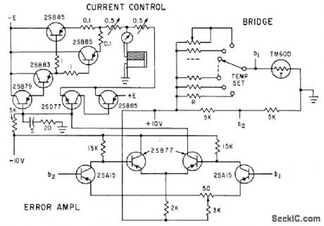
Temperature inside cooling chamber is sensed by thermistor bridge and bridge output is com pared with temperature-setting reference voltage. Difference voltage is amplified and fed to current control circuit of thermoelectric converter.-M. Nagata and Z. Abe, Thermoelectric Elements for Circuit Cooling, Electronics, 34:41, p 54-55. (View)
View full Circuit Diagram | Comments | Reading(1582)
Color_TV_chroma_processor_with_ACC_color_killer_and_an_injection_lock_reference_system
Published:2009/7/21 8:58:00 Author:Jessie
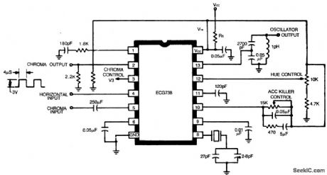
Color TV chroma processor with ACC, color killer, and an injection lock reference system. fypical power supply voltage is 9 to 11.5 volts. Hue control range is 100 degrees. The oscillator output signal is 180 mV PMS (courtesy GTE Sylvania Incorporated). (View)
View full Circuit Diagram | Comments | Reading(988)
TV_color_IF_amplifier_and_detector
Published:2009/7/21 8:56:00 Author:Jessie
TV color IF amplifier and detector. This configuration will provide approximately 84 dB voltage gain. The nominal 3-volt peak-to-peak output can be varied between 0 and 7 volts with excellent linearity and freedom from spurious output products. Alignment is most easily accomplished with an AM generator set at a carrier frequency of 45.75 MHz, modulated with a video frequency sweep. The detector tank is first adjusted for maximum detected DC witlra CW input. Next the video sweep modulation is applied in order to align the input and interstage circuits (courtesy GTE Sylvania Incorporated). (View)
View full Circuit Diagram | Comments | Reading(879)
TV_video_IF_amplifier_with_low_level_detector
Published:2009/7/21 8:55:00 Author:Jessie

TV video IF amplifier with low-level detector (courtesy Motorola Semiconductor Products Inc.). (View)
View full Circuit Diagram | Comments | Reading(1890)
TV_video_IF_amplifier_with_detector_stage
Published:2009/7/21 8:53:00 Author:Jessie
TV video IF amplifier with detector stage (courtesy Motorola Semiconductor Products Inc.). (View)
View full Circuit Diagram | Comments | Reading(1081)
TV_VHF_tuner_using_dual_gate_MOSFETs
Published:2009/7/21 8:52:00 Author:Jessie
TV VHF tuner using dual-gate MOSFETs (courtesy Texas Instruments Incorpo rated). (View)
View full Circuit Diagram | Comments | Reading(1511)
AFT_circuit_for_TV_with_detailed_coil_winding_data
Published:2009/7/21 8:50:00 Author:Jessie

AFT circuit for TV with detailed coil winding data (courtesy GTE Sylvania Incor porated).
(View)
View full Circuit Diagram | Comments | Reading(887)
TV_AFT_AFC_circuit_for_three_types_of_systems_using_an_ECG1046_14_pin_DIP
Published:2009/7/21 8:48:00 Author:Jessie
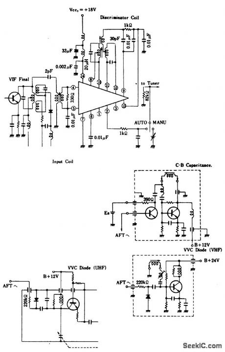
TV AFT/AFC circuit for three types of systems using an ECG1046 14-pin DIP. The ECG1046 contains two VIF differential amplifiers, a phase detector, and a DC amplifier, whose output is supplied to a varactor diode in a tuner. It has the additional feature of having an internal regulated voltage supply. Partial tuner circuits shown are only for example applications. Coils and transformers should be selected to match the IF and can be obtained from discarded TV receivers or purchased at a local electronics parts jobber (Merit or Miller components). Maximum supply voltage for the ECG1046 is 20 volts (courtesy GTE Sylvania Incorporated). (View)
View full Circuit Diagram | Comments | Reading(832)
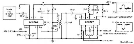
Complete_TV_video_IF_amplifier_and_detector_system
Published:2009/7/21 8:45:00 Author:Jessie
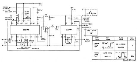
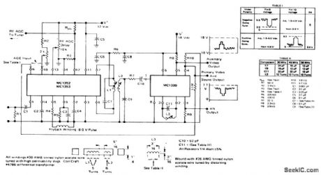
Complete TV video IF amplifier and detector system. The ECG749 contains two lF amplifiers, an AGC keyer, and an AGC amplifier; The circuit will work for both color and B&W. See table for AGC information (courtesy GTE Sylvania Incorporated). (View)
View full Circuit Diagram | Comments | Reading(785)
Electrono_tuner_contror_memory_for_radio_and_TV
Published:2009/7/21 8:43:00 Author:Jessie
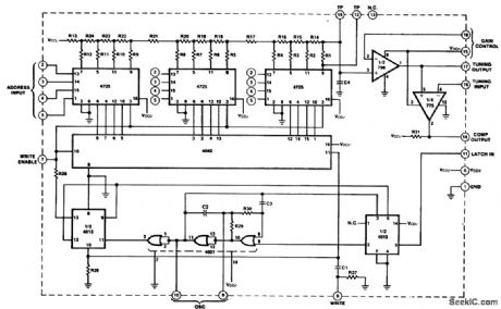
Electrono tuner contror/memory for radio and TV. The SH1549 gives capability of storing and recalling up to 16stations in addition to conventional varactor tuning. The SH 1549 converts the analog tuning voltage into a 12-bit digital word and stores it in memory for future use (courtesy Fairchild Semiconductor). (View)
View full Circuit Diagram | Comments | Reading(841)
ColorTV_horizontal_self_regulating_scan_circuitry_fora_19_inch_receiver
Published:2009/7/21 8:33:00 Author:Jessie

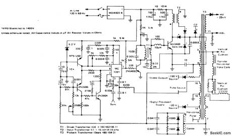
ColorTV horizontal self-regulating scan circuitry fora 19-inch receiver (courtesy Motorola Semiconductor Products Inc.).
(View)
View full Circuit Diagram | Comments | Reading(830)
_Color_TV_chroma_processor_using_an_ECG1089_20_pin_DIP
Published:2009/7/21 7:51:00 Author:Jessie
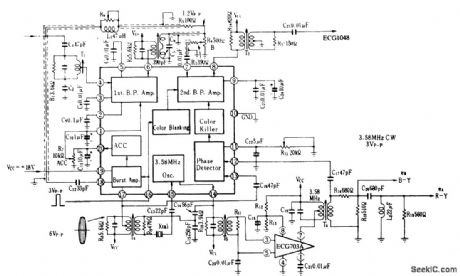
Color TV chroma processor using an ECG1089 20-pin DIP. The ECG1048 noted on the schematic is a chroma demodulator The ECG703A is a 3.58 MHz amplifier(courtesy GTE Sylvania Incorporated) (View)
View full Circuit Diagram | Comments | Reading(933)
Color_TV_358_MHz_crystal_oscillator_using_adual_gate_MOSFET
Published:2009/7/21 7:47:00 Author:Jessie
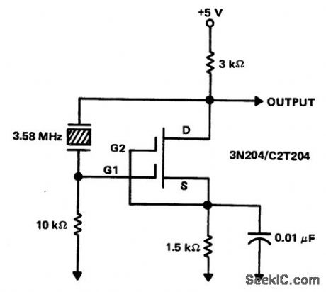
Color TV 3.58 MHz crystal oscillator using adual-gate MOSFET (courtesy Texas Instruments Incorporated). (View)
View full Circuit Diagram | Comments | Reading(990)
TV_vertical_deflection_system
Published:2009/7/21 7:46:00 Author:Jessie
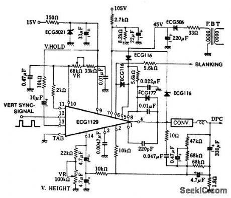
TV vertical deflection system (courtesy GTE Sylvania Incorporated). (View)
View full Circuit Diagram | Comments | Reading(892)
PULSER_FOR_250_KW_MODULATOR
Published:2009/7/21 7:59:00 Author:Jessie

Trigger generator for scr modulator uses, two-layer and four-layer diodes to provide pulse burst, repetition rates up to 25 kc.-H.G. Heard, Controlled Rectifier Produces Quarter-Megatwatt Pulse Power, Electronics, 34:25, P 54-55. (View)
View full Circuit Diagram | Comments | Reading(735)
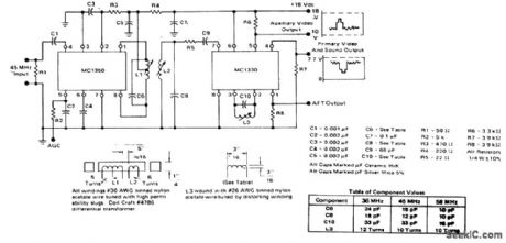
Complete_FM_TV_45_MHz_sound_channel_using_an_ECG1045_14_pin_DIP
Published:2009/7/21 7:57:00 Author:Jessie
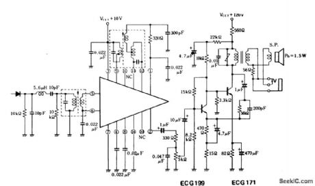
Complete FM/TV 4.5 MHz sound channel using an ECG1045 14-pin DIP. Audio power output is 1.5 watts. The ECG1045 contains a three-state high-gain directional IF amplifier and a ratio detector. IF transformers and the AF output transformer are standard items and can be purchased at Radio Shack. This circuit can be modified for 10.7 MHz operation by selecting the proper IF transformers (courtesy GTE Sylvania Incorporated). (View)
View full Circuit Diagram | Comments | Reading(1008)
ColorTV_demodulator_with_color_amplifiers
Published:2009/7/21 7:54:00 Author:Jessie
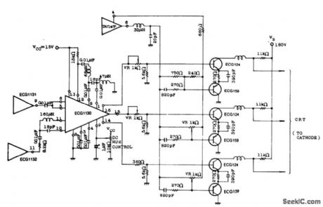
Color TV demodulator with color amplifiers. The ECG1131s shown are chroma signal amplifiers. The ECG1130 is a 16-pin DIP (courtesy GTE Sylvania Incorporated). (View)
View full Circuit Diagram | Comments | Reading(824)
Varactor_UHF_TV_tuner_using_a_3N225_dua_gate_MOSFET
Published:2009/7/21 8:30:00 Author:Jessie
Varactor UHF TV tuner using a 3N225 dua-gate MOSFET(courtesy Texas Instruments Incorporated). (View)
View full Circuit Diagram | Comments | Reading(1428)
TV_IF_amplifier_with_video_detector_and_sound_takeoff_using_dual_gate_MOSFETs
Published:2009/7/21 8:29:00 Author:Jessie

TV IF amplifier with video detector and sound takeoff using dual-gate MOSFETs (courtesy Texas Instruments Incorporated). (View)
View full Circuit Diagram | Comments | Reading(843)
TV_IF_amplifier_uslng_dual
Published:2009/7/21 8:27:00 Author:Jessie
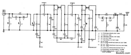
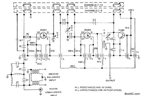
TV IF amplifier uslng dual-gate MOSFETs The IF response is as follows∶39.75 MHz greater than 30 dB down, 41.25 MHz greater than 40 dBdown,47.25 MHz greater than 30 dB down,42.17 nealy 8 dB down,45.75 MHz equalto 6 dB down.Senstivity is 700 μV for 1V of video carrier at 100% modulation.AGC range is 43 dB AGC voltage is +4.0 V to-6.0V.Sound output is 570μV of 4.5 MHz signal(courtesy Texas Instruments Incorporated).
(View)
View full Circuit Diagram | Comments | Reading(828)
| Pages:40/126 At 202122232425262728293031323334353637383940Under 20 |
Circuit Categories
power supply circuit
Amplifier Circuit
Basic Circuit
LED and Light Circuit
Sensor Circuit
Signal Processing
Electrical Equipment Circuit
Control Circuit
Remote Control Circuit
A/D-D/A Converter Circuit
Audio Circuit
Measuring and Test Circuit
Communication Circuit
Computer-Related Circuit
555 Circuit
Automotive Circuit
Repairing Circuit