
Electrical Equipment Circuit
Index 24
TOUCH_TONE_DIALER
Published:2009/7/14 21:34:00 Author:May
Single Motorola 4410 chip requires only two external components and 2-of-8 keyboard to generate two sine waves simultaneously for Touch-Tone dialing and telephone modem communication. Each key on keyboard grounds one of C inputs and one of R inputs. As example, when 6 key is pressed, R2 and C3 are grounded to give 770-Hz sine wave on pin 2 and 1477-Hz sine wave on pin 15. Designed for driving 1K load. Output voltage is about 600 mV P-P for low output and 800 mV P-P for high output.-D. Lancaster, CMOS Cook-book, Howard W. Sams, Indianapolis, IN, 1977, p 132. (View)
View full Circuit Diagram | Comments | Reading(1353)
VIDEO_FADER
Published:2009/7/14 21:34:00 Author:May
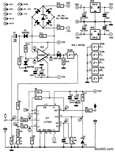
The circuit shown here does an adequate job of allowing you to fade a video signal virtually down to the black level without losing sync on the monitor. The sync pulses are extracted from the composite video (CVBS signal) by op amp IC2 and its surrounding components. Components C2, R11, and D2 form a video-clamping circuit. Diode D3 provides a bias at the + input of IC2. Because of the rectifying action of D2, the op amp amplifies only the negative part of the CVBS signal. The clamping circuit in the feedback path of the AD847 (D5 to D8) prevents the op amp from going into saturation. The amplifier sync signal is digitized by a diode, D9, and a Schmitt-trigger gate, IC3d, before it is appied to the + input of one of the two fast op amps contained in the video fader IC, an LT1251.The sync level is set to the optimum level with the aid of preset P1. The LT1251 uses preset P2 to determine the level ratio between the sync channel and the video channel. The control voltage for the fader is derived from a reference voltage created by zener diode D1. The mixed output signal is available at pin 8 (dc-coupled), at an impedance of about 75Ω. Current consumption of the circuit is less than 30 mA. The indicated test voltages are applicable with no input signal applied to the circuit. The fader also reduces the level of the color burst. Consequently, the picture can go black and white just before the black level is reached. (View)
View full Circuit Diagram | Comments | Reading(3375)
MOBILE_AUTOPATCH
Published:2009/7/14 21:12:00 Author:May

Circuit operates push-to-talk of mobile station automatically when any button on Touch-Tone pad is pushed for dialing telephone number after making auto patch, eliminating need for engaging microphone before dialing. Circuit remains active for about 2 s after Touch-Tone button is released.-Circuits, 73 Magazine, May 1977. p 19. (View)
View full Circuit Diagram | Comments | Reading(1412)
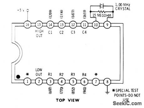
TONE_ENCODER
Published:2009/7/14 20:48:00 Author:May
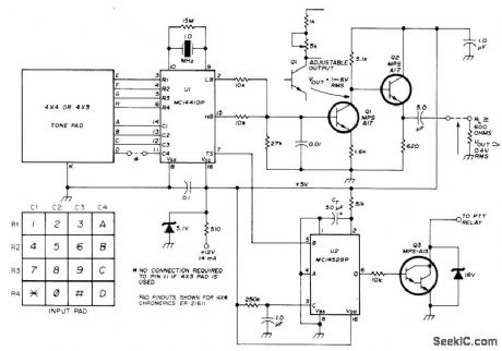
Motorola MC14410 CMOS IC is basis of accurate low-power Touch-Tone encoder system providing full 2-of-8 encoding from basic 1-MHz crystal oscillator. Can be used with 2-of-7 or 2-of-8 keypad switch matrix such as Chromerics ER-21623 or ER-21611. Q1-Q2 form tone-amplifiet/emitter-follower line driver. U2 is push-to-talk mono 1-s timer. Supply can be any voltage from 5to 12V if zener is used to supply 5 V to ICs. Article covers circuit operation in detail and gives tone-encoder frequency table.-J. DeLaune, Digital Touch-Tone Encoder for VHF FM, Ham Radio, April 1975, p 28-31.
(View)
View full Circuit Diagram | Comments | Reading(0)
TOUCH_TONE_ENCODER_1
Published:2009/7/14 20:36:00 Author:May
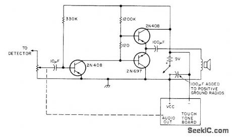
Consists of SME Touch-Tone generator and keyboard made by Data Signal (Albany, GA) mounted on any small transistor radio. Only audio section is used, with output tones from loudspeaker being fed acoustically to microphone of FM amateur station. Article gives construction details,-D. In-gram, The Shirt Pocket Touch-Tone, 73 Magazine, Nov. 1976, p 58-59. (View)
View full Circuit Diagram | Comments | Reading(1102)
SINGLE_TONE_DECODER
Published:2009/7/14 8:11:00 Author:May
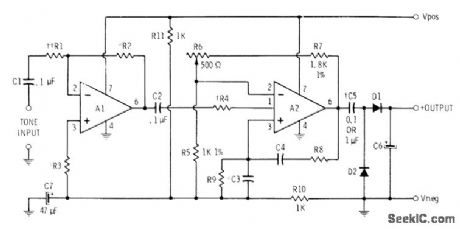
Used at receiving end of leased telephone line in which single tone frequency serves for alarm and other purposes. A1 is 741 opamp connected as inverting amplifier, with R1 and R3 chosen to match input impedance and R2 chosen to give gain required for available input signal level. For 10K input impedance, R1 and R3 are 10K and R2 in kilohms is 10 times required gain (500K for gain of 50). Actual tone decoding is performed by A2, which is also 741; here C3, C4, R8, and R9 are frequency-determining components and R6 is gain control. R4 is chosen to give desired bandwidth ; use 470K for 5-10%, 1 meg ohm for 3-5%, and 2.2 meg ohms for 1-3%. R8 is same as R2, and R9 equals R3. Diodes are 1N914.-C. D. Rakes, Integrated Circuit Projects, Howard W. Sams, Indianapolis, IN, 1975, p 60-66. (View)
View full Circuit Diagram | Comments | Reading(1054)
FM_FOR_INSTRUMENTATION
Published:2009/7/14 8:07:00 Author:May
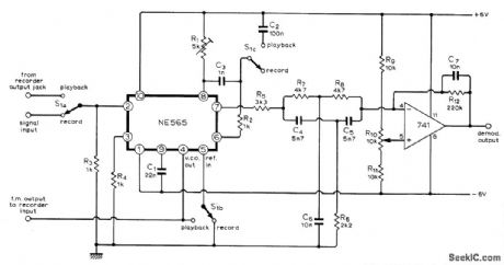
Frequency modulator-demodulator circuit using IC and opamp converts ordinary low-cost tape recorder into instrumentation recorder. Signetics NE565 phase-locked loop serves for both modulation and demodulation. Frequency response of 0-800 Hz is suitable for recording VLF phenomena at tape speed of 9.1 cm/s (3.5 in/s). Carrier frequency is in midband, at 3 kHz. Article covers circuit operation in detail and gives de-sign equations.-B. D, Jordan. Simple F.M.Modulator/Demodulator for a Magnetic Tape Recorder, Wireless World, March 1974, p 29-30. (View)
View full Circuit Diagram | Comments | Reading(4100)
FSK_DETECTOR_FOR_CASSETTE_RECORDED_DATA
Published:2009/7/14 8:05:00 Author:May
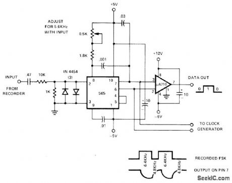
Connection shown for 565 PLL provides data output of 1 for 6.4 kHz and 0 for 4.8 kHz from ordinary cassette tape recorder having frequency response to 7 kHz. Report gives circuit of suitable recorder using return-to-zero FSK. System also requires 800-Hz clock generator for synchronizing to data. Up to seven 0s can occur in succession without making clock go out of sync. Odd parity is used.- Signetics Analog Data Manual, Signetics, Sunnyvale, CA, 1977, p 857-859. (View)
View full Circuit Diagram | Comments | Reading(1953)
FSK_GENERATOR_FOR_CASSETTE_DATA
Published:2009/7/14 7:54:00 Author:May
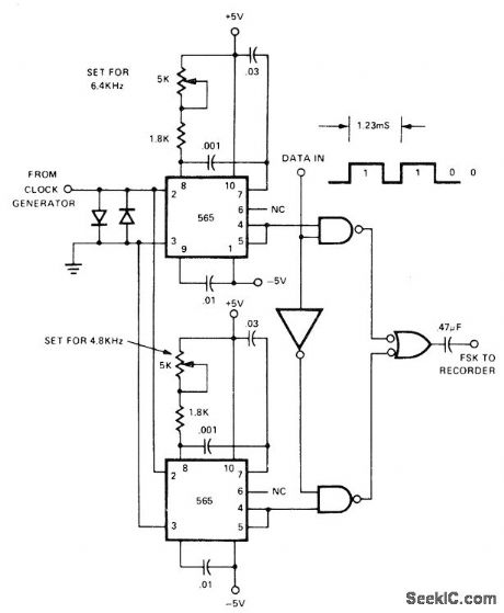
Uses two 565 PLL ICs, locked to 800-Hz system clock but oscillating at 6.4 kHz and 4.8 kHz, to provide FSK signals for recording digital data on ordinary cassette tape. Harmonic suppression of square-wave output is taken care of automatically by high-frequency roll off characteristic of tape recorder. Incoming data determines which oscillator feeds its signal to recorder.- Signetics Analog Data Manual, Signetics, Sunnyvale, CA, 1977, p 859-860.
(View)
View full Circuit Diagram | Comments | Reading(1005)
BELL_SIMULATOR
Published:2009/7/14 6:08:00 Author:May

Uses AMI S2561 CMOS IC to simulate effects of telephone bell by producing tone signal that shifts between two predetermined frequencies at about 16 Hz. In applications where dial pulse rejection is not necessary, network inside dashed lines can be omitted and pins EN and D1 connected directly to VDD, which is typically 10V. Power is derived from telephone lines by diode-bridge supply. Values shown give tone frequencies of 512 and 640 Hz. Power output to 8-ohm loudspeaker is at least 50 mW, fed through 200:8 ohm trans-former.- Tone Ringer, American Microsystems, Santa Clara, CA, 1977, 52561, p 1. (View)
View full Circuit Diagram | Comments | Reading(1077)
CONSTANT_CURRENT_DIODE_AS_COLLECTOR_LOAD
Published:2009/7/14 5:41:00 Author:May

Current-limited Currector diode isolates transistor amplifier output from changes in supply volatge and serves also as collector load impedance. Gain is over 60 db at 50 to 100kc.-N. Welsh. How Diodes Keep Current to Constant Value. Electronics.36:4,p74-78 (View)
View full Circuit Diagram | Comments | Reading(0)
DIGITAL_CASSETTE_HEAD_DRIVE
Published:2009/7/14 5:29:00 Author:May
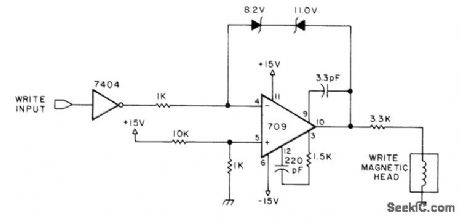
Provides saturation recording as required for digital data. Back-to-back zeners provide bipolar limiting at ±10V, TTL-level inputs are applied to write data input, inverted by 7404, and fed to inverting input of opamp. Noninverting opamp input is INPUT referenced to +1.4 V so output will switch polarities when TTL level of input changes.-I. Rampil and J. Breimeir, The Digital Cassette Subsystem: Digital Recording Background and Head Interface Electronics, BYTE, Feb. 1977, p 24-31. (View)
View full Circuit Diagram | Comments | Reading(988)
CASSETTE_DATA_READOUT
Published:2009/7/14 5:15:00 Author:May
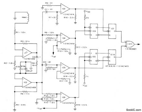
Uses separate circuits haying threshold provisions for both positive and negative peaks, for reading data stored on cassette tape at 15 in/s. Head output signal is 10 mV. Phase encoding is used with 1600 flux reversals per inch. Circuit design procedure is given. Two Motorola MC1458 gain stages feed head output to passive differentiators C2-R7 and C3-R11 to generate zero crossing. Corner frequency for each differentiator is 86 kHz. IC3 and IC4 process negative-going peaks, while IC5 and IC6 process positive-going peaks. Outputs of IC4 and IC6 drive T flip-flops serving as data inputs to IC7 and IC10.- The Recovery of Recorded Digital Information in Drum, Disk and Tape Systems, Motorola, Phoenix, AZ, 1974, AN-711, p 9. (View)
View full Circuit Diagram | Comments | Reading(968)
CASSETTE_FILE_UPDATE
Published:2009/7/14 5:14:00 Author:May
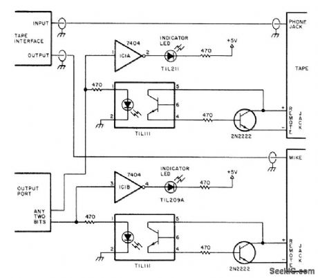
Interface circuit controls two tape decks for updating mailing lists or other sequential files stored on magnetic tape in audio cassettes. Two cassette tape recorders are required, one for input (reading files) and one for output (writing files). Micro-processor tape input and output circuits are connected to appropriate tape unit as shown. Only one cassette operates at any given time. Optocouplers prevent polarity or voltage problems between tape motor and microprocessor. Tape functions are under software control. Soft-ware delay of about is allows tape motor to come up to speed before recording starts. Records are in numerical or other logical sequence, so updating requires only one pass. On update, old cassette file is read into microprocessor for deletion, change, or addition of data, and corrected data is written on new cassette. Article covers use for maintaining Christmas card and other mailing lists, payroll records sequenced by Social Security number, and other sequential lists.-W. D. Smith, Fundamentals of Sequential File Processing, BYTE, Oct. 1977, p 114-116, 118, 120, 122, 124, and 126-127. (View)
View full Circuit Diagram | Comments | Reading(1443)
TEMPERATURE_COMPENSATED_MILLIVOLT_REFERENCE
Published:2009/7/14 4:44:00 Author:May

Two identical diodes are used to derive a temperature -compensated voltage across R2. Select two diodes of the same manufacture with, for example, 10-mV difference in forward drop at the same current. Then the output will be compensated because both diodes will very likely have the same temperature coefficient (they are of identical manufacture). (View)
View full Circuit Diagram | Comments | Reading(1152)
TEMPERATURE_MONITOR
Published:2009/7/14 4:41:00 Author:May
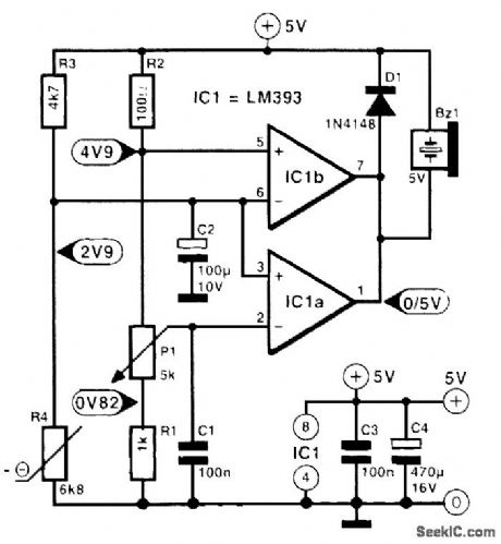
The temperature sensor is a resistor, R4, with negative temperature coefficient (NTC); the resistance of such a resistor drops when its temperature rises. Resistors R4 and R3 are part of a resistance bridge whose variable branch consists of R1, R2, and P1. The metering diagonal is connected to the inputs of comparator IC1a. The voltage at the inverting input of IC1a is set with P1 to a level that with normal temperatures is a little lower than that at the noninverting input. When the temperature rises, the resistance of R4 falls. This results in the comparator's changing state (to low), which causes the piezo buzzer to sound. Care should be taken to ensure that the voltage across the metering diagonal does not drop below 3.5 V to prevent the common-mode dynamic range of the LM393 from being exceeded. The NTC can be a 5- or a 10-kΩ type. It must be in good thermal con-tact with the heat source. Preset P1 must be set to a position where, after the part or device being monitored has attained normal operating temperature, the buzzer just does not sound. The buzzer must be a 5-V type. (View)
View full Circuit Diagram | Comments | Reading(0)
SOLID_STATE_THERMOMETER
Published:2009/7/14 4:38:00 Author:May
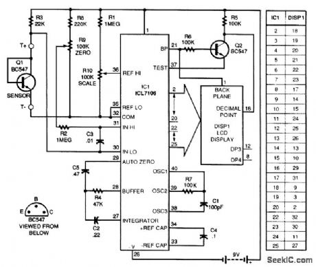
The AM ICL7106 31/2-digit analog-to-digital converter by Harris Semiconductor reads the -2.2-mV/°C change in the junction voltage drop of a BC547 transistor. R9 and R10 provide calibration. The basic chip has a 0- to 199.9-mV range. An LCD display made by Varitronix is used as a readout, The dc input voltage is correlated with the ambient temperature surrounding Q1. (View)
View full Circuit Diagram | Comments | Reading(3634)
CVSD_ENCODER_FOR_SECURE_RADIO
Published:2009/7/14 4:36:00 Author:May
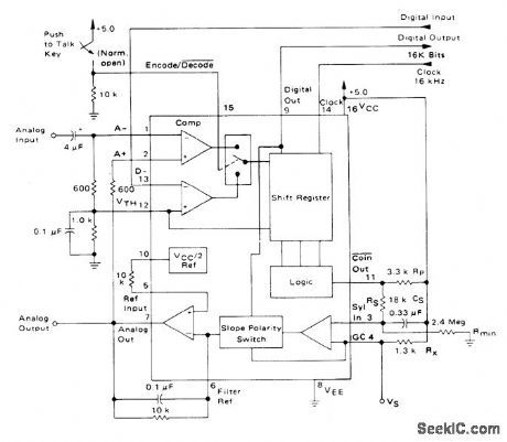
Motorola MC3417 continuously variable slope delta modulator-demodulator IC is used as 16-kHz simplex voice coder-decoder for systems requiring digital communication of analog signals. Clock rate used depends on bandwidth required and can be 9.6 kHz or less for voice-only systems. Analog output uses single-pole integration network formed with 0.1μF and 10K. Report covers circuit operation in detail for various applications.- Continuously Variable Slope Delta Modulator/Demodulator, Motorola, Phoenix, AZ, 1978. DS 9488 (View)
View full Circuit Diagram | Comments | Reading(1845)
PC_TEMPERATURE_INTERFACE
Published:2009/7/14 4:35:00 Author:May
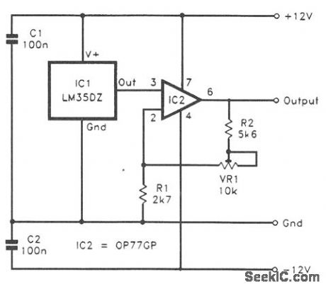
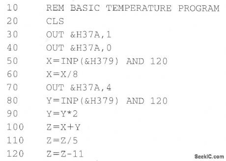
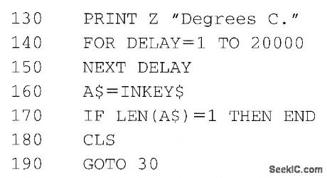
This simple temperature interface covers a range of 0 to 51°C. Dual balanced 12-V supplies were used to power the prototype, but dual 5-V supplies should just about suffice. IC1 is the temperature sensor. Over this range of temperatures, the LM35CZ should work well. The output from IC1 feeds into a noninverting-mode amplifier based on IC2. The closed-loop voltage gain of the amplifier is set by resistors R1 and R2 and preset VR1. The latter is adjusted to give a voltage gain of 5. VR1 is given the correct setting by first subjecting the sensor to a temperature, which is equal to about 50 or 100 percent of the full-scale value (i.e., about 20 to 51°C.). In most cases, the room temperature will be about 20 to 25°C, which will suffice. An accurate thermometer is used to measure the room temperature, and then VR1 is adjusted for the appropriate reading.
The following GW Basic or Q BASIC program reads the temperature sensor and prints the temperature on the screen: (View)
View full Circuit Diagram | Comments | Reading(1800)
LINEAR_READOUT_CIRCUIT
Published:2009/7/14 4:30:00 Author:May

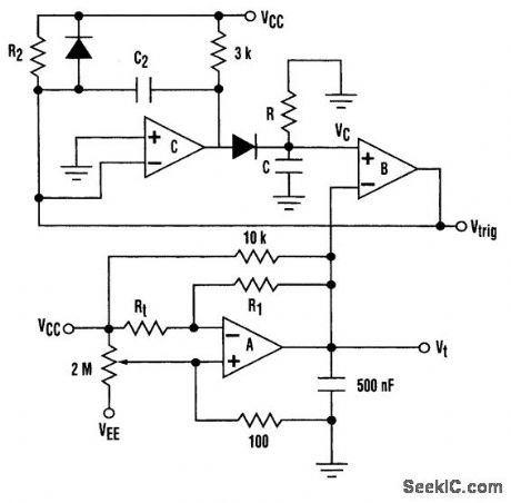
Thermistors have found their way into a number of temperature-sensing applications. However, their resistance is a nonlinear function of temperature. In many applications, a digital readout of the thermistor also is desired. It is possible to produce a digital signal with a frequency that is linearly proportional to the temperature. The entire active portion of the circuitry can be implemented using 3/4 of an LM339. Comparator A is configured to operate as an op amp that generates voltage (Vt) which is inversely proportional to the thermistor's resistance, Rt. The voltage Vt is used as the thresh-old for the relation oscillator formed by comparators B and C. Comparator B monitors the voltage on the integrating capacitor (Vc). When it crosses Vt, it triggers the one-shot formed by comparator C via the signal Vtrig The output of comparator C resets the integrating capacitor for a duration, to, where to= (R2+3 kΩ)C2. Then the cycle begins again. The circuit achieves linear readout because the exponential nonlinearity of the thermistor is compensated by the exponential decay of the voltage in the relaxation oscillator. (View)
View full Circuit Diagram | Comments | Reading(1102)
| Pages:24/126 At 202122232425262728293031323334353637383940Under 20 |
Circuit Categories
power supply circuit
Amplifier Circuit
Basic Circuit
LED and Light Circuit
Sensor Circuit
Signal Processing
Electrical Equipment Circuit
Control Circuit
Remote Control Circuit
A/D-D/A Converter Circuit
Audio Circuit
Measuring and Test Circuit
Communication Circuit
Computer-Related Circuit
555 Circuit
Automotive Circuit
Repairing Circuit