
Electrical Equipment Circuit
Index 23
Ding-dong electronic doorbell
Published:2011/8/7 21:09:00 Author:Ecco | Keyword: Ding-dong electronic doorbell
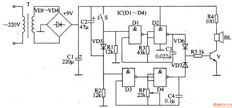
The ding-dong electronic doorbell circuit is composed of the power supply circuit, trigger control circuit, audio oscillator output circuit, and it is shown in Figure 3-125. Power supply circuit is composed of the power transformer T, rectifier diodes VDl-VD4 and filter capacitor Cl. Trigger control circuit is composed of the doorbell button, control circuit S, diode VD5, capacitor C2 and resistors Rl, R2. Audio oscillator A consists of the Dl, D2 which are inside of four NAND gate IC (Dl-D4) and resistor R3, capacitor C3. Audio oscillator B consists of the D3, D4 which are inside of IC and potentiometer RP, capacitor C4. Audio output circuit consists of resistors R4, R5, diodes VD6, VD7, transistor V, and the speaker BL.
(View)
View full Circuit Diagram | Comments | Reading(3879)
Politely welcoming electronic doorbell
Published:2011/8/7 21:38:00 Author:Ecco | Keyword: Politely welcoming, electronic doorbell
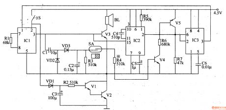
The politely welcoming electronic doorbell circuit is composed of the trigger control circuit, audio amplifier output circuit, music circuit, voice delay control circuit, and it is shown in Figure 3-122. Trigger control circuit is composed of the doorbell button S, magnetic switches SA, transistors V4, V5, resistors R3, R4, R6, diodes VD2, VD3, and capacitors Cl, C2. Audio amplifier output circuit consists of transistor V3 and speaker BL. The music circuit consists of music integrated circuit ICl and resistor Rl. Voice circuit is composed of the voice IC lC2 and resistor R5, capacitors C4, C5.
(View)
View full Circuit Diagram | Comments | Reading(2087)
Recordable electronic doorbell
Published:2011/8/7 21:43:00 Author:Ecco | Keyword: Recordable electronic doorbell
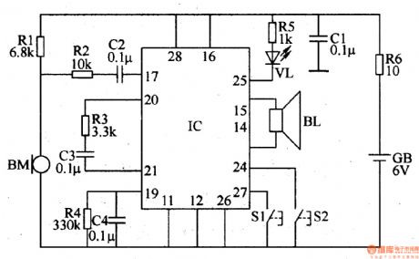
The recordable electronic doorbell is composed of the recording and playback integrated circuit IC, resistors Rl-R6, capacitors Cl-C4, microphone BM, speaker BL, control buttons Sl, S2, battery GB and LED VL, and it is shown in Figure 3-123. Rl-RS select 1/4W metal film resistors or carbon film resistors; R6 select the lW metal film resistor. Cl-C4 select monolithic capacitors. VL chooses the φ3mm green light-emitting diode. IC uses the SR9GlOA or ISDll10 audio recording and playback IC. S1 select the miniature moving together button; S2 uses the bell button. BL uses the 0.25W, 8Ω dynamic speaker.
(View)
View full Circuit Diagram | Comments | Reading(3021)
The improvement of 555 Great Wall floor fan electronic selection time circuit
Published:2011/8/4 9:00:00 Author:nelly | Keyword: Great Wall, floor fan, selection time
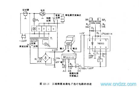
The great wall FS7-40 floor fan adopts the general mechanical electromagnetic relay,as a result,when we are shifting,it's always being the mechanical metal contact's contacting and opening which produces the mechanical noise and discharge spark. Using solid relay and connecting control circuit which consists of 555 can solve this problem. The figure 12-16 is an improved selection time circuit.The solid relay adopts sp1110-2.Its input voltage is between 2vand 6v,and the input current is between 10mAand 50mA,the on state current is 3A. To avoid the influence of the power voltage's change on the triggering and turn-on,we should use w7805 or w7806 to stabilize the +12V original power voltage. Through changing the vibration period and the Duty ratio can Change the RP1 and RP2. The R3 is the relay's limiting current.The D3 is used for the relay's over voltage protection.The R4 and C2 is used for absorpting the surge current to increase the safety.
(View)
View full Circuit Diagram | Comments | Reading(1567)
The bridge type T circuit of reducing the components of Notch filter
Published:2011/8/7 4:15:00 Author:Sophia | Keyword: The bridge type T circuit, reducing the components of Notch filter

The double-T circuit with less number of components achieves the notch filter circuitry, as well known as the T-bridge circuit, its application is few . Figure 1 is a typical example. In the circuit, the arrangement of substitute resistors and capacitors is neglected because of imbalanced value of capacitance. In this circuit, the ratio of resistors R1 and R2 make zero frequency with the largest attenuation changed. When R1 = R2 = 16kΩ, C = 0.01μF, fo = 11kHz, a large amount of attenuation is available. But when it is used, the condition is R1> R2, which is not very simple. (View)
View full Circuit Diagram | Comments | Reading(2030)
Eggs hatching incubator circuit diagram 3
Published:2011/8/5 1:59:00 Author:Ecco | Keyword: Eggs hatching incubator
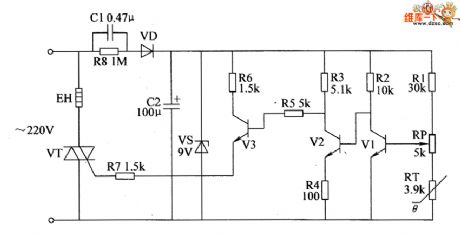
The eggs hatch incubator circuit is composed of the power supply circuit and temperature control circuit, and it is shown as the chart. Step-down power supply circuit is composed of the capacitor C1, discharge resistor R8, rectifier diode VD, filter capacitor C2 and zener diode VS. Temperature control circuit is composed of resistors R1 ~ R7, potentiometer RP, thermistor RT, transistors V1 ~ V3 and the intergranular tube VT. R1 ~ R8 select the 1/4W metal film resistors or carbon film resistors. RT uses the thermistor with negative temperature coefficient. RP uses the synthetic membrane or precision multi-turn potentiometer.
(View)
View full Circuit Diagram | Comments | Reading(2817)
Eggs hatching incubator circuit diagram 2
Published:2011/8/5 1:55:00 Author:Ecco | Keyword: Eggs hatching incubator
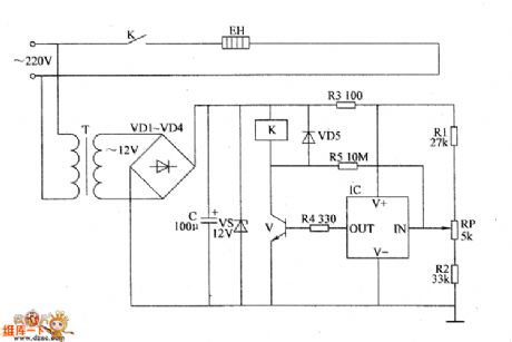
The eggs hatch incubator circuit is composed of the power supply circuit and temperature control circuit, and it is shown as the chart. Power supply circuit is composed of the power transformer T, rectifier diodes VD1 ~ VD4, filter capacitor C and zener diode VS. Temperature control circuit consists of resistors RI ~ R5, potentiometer RP, diode VD5, temperature sensor integrated circuit IC, transistor V, Relay K and electric heater EH. R1 ~ R5 select the 1/4W metal film resistors or carbon film resistors. RP uses the small synthetic membrane potentiometer or multi-turn potentiometer. VD1 ~ VD5 select 1N4007 silicon rectifier diodes.
(View)
View full Circuit Diagram | Comments | Reading(3912)
Glanz WD900B Microwave Oven Defect Circuit
Published:2011/8/5 19:18:00 Author:Robert | Keyword: Glanz, Microwave Oven, Defect
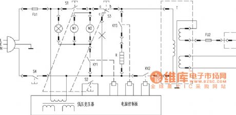
By detailed analysis according to the circuit (shown in the picture), its is tested to know that the S1 would be disconnected when openning the oven door and it would be connected when closing the oven door. The S3 would connect the ac when openning the oven door and it would connect ab when closing the oven door. Which means the S1 is changed to be connected and the S3 is changed from connecting the a to c to from connecting the a to b when closing the oven door. Obviously, the wire connecting to the S3's C port is unnecessary. So if the S3 has been used for a long time and its switching performance has reduced, the S1 may has been connected before closing the oven door. Because the S3 has not changed its mode which is from connecting a to c to connecting a to b. So it could cause the short circuit. So it should remove the wire which connecting to S3 switch's C port (the practical object is a red wire and a blue wire are twisted together and then they are inserted to the switch's C port). That means it should disconnect the position of x in the picture. Then it would be normally used when it is electrified again. (View)
View full Circuit Diagram | Comments | Reading(1198)
Converter Circuit With Non-Resonant Feature
Published:2011/8/4 10:35:00 Author:Robert | Keyword: Converter, Non-Resonant, Feature
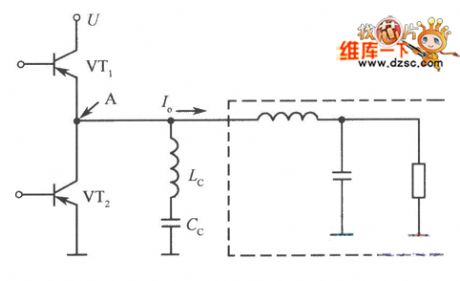
The converters, which are named with part-resonance, multi-resonance, current commutation type and so on, are the zero voltage switch converters with this feature. And the inductance commutation type converter even be used as zero voltage switch in non-resonant mode from the principle, it also has few cases of the surge phenomena. And also it could adjust the voltage by the PWM control. The picture is the basic circuit of this mode. The Lc is the inductance for current commutation. The Cc is the capacitor for cutting the DC power (not for non-resonant using). In this mode, the VT1 and VT2 would alternately and continuously turn on and turn off. (View)
View full Circuit Diagram | Comments | Reading(904)
Black-And-White Wall Hanging Visible Doorbell Circuit
Published:2011/8/5 8:12:00 Author:Robert | Keyword: Black-And-White, Wall, Hanging, Visible, Doorbell
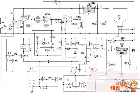
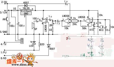
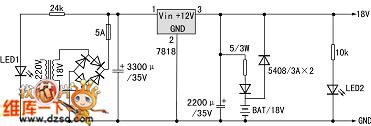
As the people's life level in our country is higher than before, some home security products have entered the house gradually. And the visible doorbell's price is going from the original thounds yuan per set to now hundreds yuan per set. It enters the home with geometric popularizes speed.The home installing the visible doorbell's purpose is to enhance the security. If adding a electromagnetic locks and automatic door closer, the user could enjoy the modern life that control the door to open or close without going out.To assemble a visible doorbell by yourself, it needs the following elements: a 38x35 standard size black-and-white camera, a 4-inch black-and-white display module, outdoor device and indoor device and 18V power case which are totally three sets, two control circuit boards, one power board, several electronic elements, one set of colourful product outer packing. The optional component is listed here: a electric control lock, a automatic door closer. (View)
View full Circuit Diagram | Comments | Reading(895)
Automatic Lighting Doorbell Circuit
Published:2011/8/5 9:14:00 Author:Robert | Keyword: Automatic, Lighting, Doorbell
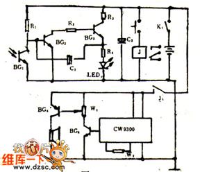
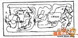
When in the night and the veranda also has not light, the doorbell's button is hard to find, especially for the new visitors. They could only knock the door. If adding a LED on the doorbell button switch, and the LED would automatically flash in the night. And it would automatically shut down in the day. This would provide the convenience for the visitors.The picture 1 shows the automatic lighting doorbell circuit.When the power switch K1 is closed, the phototransistor BG1's resistance would be reduced as it is under the light in the day. And the BG2 tube's base polar's voltage would also be reduced to make the BG2, BG3 be not conducted. Then the circuit would stop workng and the LED would not flash.
(View)
View full Circuit Diagram | Comments | Reading(1148)
Eggs hatching incubator circuit diagram 1
Published:2011/8/5 1:50:00 Author:Ecco | Keyword: Eggs hatching incubator
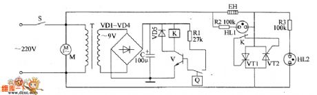
The eggs hatch incubator circuit is composed of the power supply circuit, temperature detection control circuit and indication circuit, and it is shown as the chart. Power supply circuit is composed of the power switch S, power transformer T, rectifier diodes VD1 ~ VD4 and filter capacitor C. Temperature detection control circuit is composed of electric hot thermometer Q, resistor R1, transistor V, Relay K, diode VD5, thyristors VT1, VT2 and fan motor M. Indicating circuit consists of resistors R2, R3 and neon lights HL1, HL2.
(View)
View full Circuit Diagram | Comments | Reading(1522)
Eggs automatic incubator circuit diagram 3
Published:2011/8/5 2:21:00 Author:Ecco | Keyword: Eggs automatic incubator
The eggs automatic incubator circuit is composed of the power supply circuit, temperature / ventilation control circuit, automatic egg turning control circuit and temperature indication circuit, and it is shown in Figure 3. Power supply circuit is composed of the power switch S3, power transformer T, bridge rectifier UR and capacitors C2 ~ C4, current limiting resistor R12 and zener diode VS. R1 ~ R17 use 1/4W carbon film resistors or metal film resistors. RP1 ~ BP5 use high-quality synthetic membrane potentiometers or multi-turn potentiometers; RP6 uses the organic solid potentiometer. C1, C4 ~ C6 and C8 select monolithic capacitors.
(View)
View full Circuit Diagram | Comments | Reading(6077)
Temperature And Humidity, Liquid Level Multipurpose Automatic Controller Circuit
Published:2011/8/5 8:48:00 Author:Robert | Keyword: Temperature, Humidity, Liquid Level, Multipurpose, Automatic, Controller
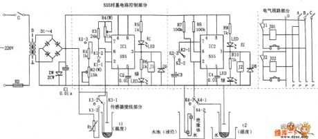
The picture shows the temperature and humidity, liquid level multipurpose automatic controller. This circuit is made up of buck rectifier filter power circuit, temperature and humidity sensor, frequency variable oscillator and single stable timing control circuit and so on. The sensor could use the thermistor, photoresistor, conductive mercury thermometer and other sensing elements. It could crossly connect the 555's charging and discharging loop circuit or the trigger port. So it would change the oscillator's frequency or 555's trigger status. When the predetermined temperature is higher than the environment temperature, the sensor's internal two mercury columns would be separate to be open circuit, so this make the IC1 reset because of the pin 2 staying in high voltage level. Then the pin 3 would output low voltage level to make the relay J1 have no action, as well as make the electrical heater's power conducted to heating. (View)
View full Circuit Diagram | Comments | Reading(2783)
Electronic ERNIE Device Circuit
Published:2011/8/5 9:41:00 Author:Robert | Keyword: Electronic, ERNIE
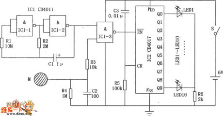
The picture shows the electronic ERNIE device's specific circuit. The IC1 is CD4011 with two input ports and four NAND gates. And the NAND gate IC1-1, IC1-2 make up the clock pulse generator, The NAND gate IC1-3 make up the counter gate circuit. Its one input port is connected with the clock pulses generator's output port and the other input port is connected to the touching metal sheet M through the resistor R3. The IC2 is decimal counter/divider CD4017. Its output ports Q0~Q9 have been added ten LED which are LED1~LED10. They are standing for 0~9 ten numbers separately. The capacitor C2 and the resistor R5 make up a electrifying automatical clearing and reset circuit. When the people's hand has not touched the metal sheet, the NAND gate IC1-3's lower input port is low voltage level, which make the counter gate closed and the IC2 would not count. (View)
View full Circuit Diagram | Comments | Reading(1265)
Eggs automatic incubator circuit diagram 2
Published:2011/8/5 2:17:00 Author:Ecco | Keyword: Eggs automatic incubator
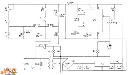
The eggs automatic incubator circuit is composed of the power supply circuit, temperature detection control circuit and eggs timing turning circuit, and it is shown as the chart. Power supply circuit is composed of the power switch S, power light HL1, power transformer T, bridge rectifier UR, filter capacitors C7 ~ CIO and three-terminal voltage regulator integrated circuit IC2. Temperature detection control circuit consists of resistors R1 ~ R6, capacitors C1 ~ C4, transistors V1, V2, thermistor RT, thyristor VT1, heating indicating lamp HL2 and heater EH. Eggs timing turning circuit is composed of the time-base integrated circuit IC1, resistors R7 ~ R9, capacitors C5, C6, thyristor VT2, motor M and eggs turning light HL3.
(View)
View full Circuit Diagram | Comments | Reading(3606)
Eggs automatic incubator circuit diagram 1
Published:2011/8/5 2:12:00 Author:Ecco | Keyword: Eggs automatic incubator
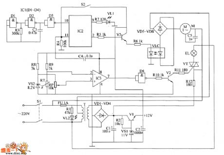
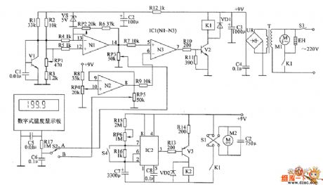
The eggs automatic incubator circuit is composed of the power supply circuit, automatic egg turning control circuit and temperature control circuit and other components, and it is shown the chart. Power supply circuit is composed of the power switch S1, fuse FU, the power transformer T, rectifier diodes VD1 ~ VD4, filter capacitors C1, C2, resistors R1, R2, power indicator LED VL2, voltage regulator VS1 and power regulator diode V1. Temperature control circuit is composed of the thermistor RT, voltage regulator diode VS2, potentiometer RP, resistors R8 ~ R12, operational amplifier integrated circuit IC3, IC1's internal NAND gate D4, transistor V2, thyristor VT and heating lighting lamp EL and other components.
(View)
View full Circuit Diagram | Comments | Reading(5884)
RGB_SYNC_COMBINER_CIRCUIT
Published:2009/7/14 21:49:00 Author:Jessie
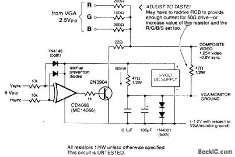
This circuit shows one way of combining RGB and sync signals from a computer to form an NTSC B/W video signal that is viewable on an ordinary video monitor.
(View)
View full Circuit Diagram | Comments | Reading(2072)
VIDEO_PATTERN_GENERATOR
Published:2009/7/14 21:47:00 Author:Jessie

A 3.58-MHz clock drives a counter chain, which addresses a preprogrammed EPROM, to generate a complete NTSC sync and video waveform. The EPROM can be programmed for various test patterns as required. A switch provides a choice of a checkerboard pattern, a color bar pattern, or a custom pattern. The total number of pixels in the custom pattern is 43,605. Each pixel can be programmed to one of the eight colors in the color bar pattern. The color signal is formed in the MC1377 encoder chip from the RGB digital inputs. The composite video out at PL1 is 2.5 V p-p. (View)
View full Circuit Diagram | Comments | Reading(1997)
MULTIRATE_VIDEO_SYNC_STRIPPER
Published:2009/7/14 22:04:00 Author:Jessie
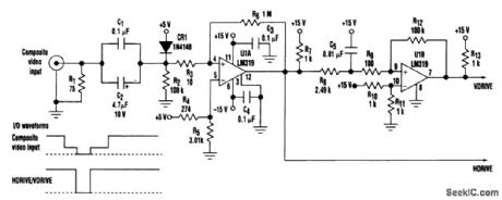
This dual-comparator, multirate video sync stripper provides separate horizontal and vertical pulses that are consistent with the composite video-input-signal sync pulses. Using an LM319 dual-comparator integrated circuit and associated passive components, this circuit can strip horizontal (HSYNC) and vertical (VSYNC) sync pulses from standard RS170 video (525/2:1 interlaced) through an industry high-end video rate of 1280 X 1024/1:1 (noninterlaced). The composite video input signal is ac-coupled through capacitors C1 and C2 to the junction of resistors R2 and R3 and diode CR1. The video sync tips are clamped by CR1 at approximately 4.5 V and applied to noninverting input of comparator U1A (pin 4). Positive feedback from resistors R6 and R3 provides a hysteresis of about l50μV to ensure a stable state change at the output of U1A (pin 12). R8 and C5 constitute a low-pass filter that prevents the filtered amplitude of the horizontal sync pulse from dropping below the threshold volt-age of 7.5 V, established by R10 and R11 for the inverting input of U1B (pin 10). R9 and R12 supply a hysteresis of about 15 mV to the noninverting input of U1B (pin 9). The inherently longer vertical sync pulse width provides sufficient time for U1A (pin l2) to be near ground. As a result C5 is adequately charged Lo exceed the threshold voltage and generate a vertical (VDRIVE) at U1B (pin 7). (View)
View full Circuit Diagram | Comments | Reading(3345)
| Pages:23/126 At 202122232425262728293031323334353637383940Under 20 |
Circuit Categories
power supply circuit
Amplifier Circuit
Basic Circuit
LED and Light Circuit
Sensor Circuit
Signal Processing
Electrical Equipment Circuit
Control Circuit
Remote Control Circuit
A/D-D/A Converter Circuit
Audio Circuit
Measuring and Test Circuit
Communication Circuit
Computer-Related Circuit
555 Circuit
Automotive Circuit
Repairing Circuit