
Electrical Equipment Circuit
Index 28
APERTURE_CORRECTING_CIRCUIT
Published:2009/7/19 23:54:00 Author:Jessie
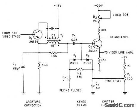
Diode D2 of keyed clamp acts as conventional peak rectifier d-c restorer for tv camera circuif. -D. G. Cartoon, Designing Transistorized Television Cameras, Electronics, 33:37, p 72-75. (View)
View full Circuit Diagram | Comments | Reading(800)
NUVISTOR_TRANSISTOR_CASCODED_TV_CAMERA_PREAMP
Published:2009/7/19 23:53:00 Author:Jessie
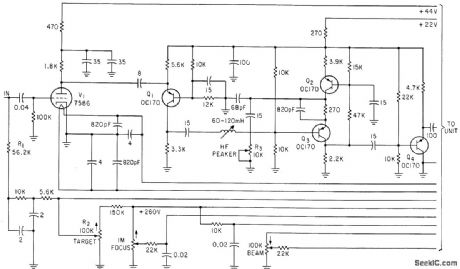
Noise figure is 3 db and video bandwidth about 6 Mc. Used with uvicon camera tube for ultraviolent telescope,-R. N. Riggs, Ultraviolet Space Telescope Will Scan the Stars, Electronics, 35:46, p 37-43. (View)
View full Circuit Diagram | Comments | Reading(977)
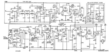
EEG_WAVEFORM_ANALYZER
Published:2009/7/20 20:40:00 Author:Jessie

Uses derivative curves of primary eeg signals to quantitatively describe waveshape deviations of irregular electrical waveforms emitted by brain, in terms of time and amplitude. Oporates on zero-crossing detector measurements to produce analog voltages proportional to time between base periods and also proportional to time values of left and right deviation coefficients.-C. J. Zaander, Computer Ancalyzes Brain Waveforms, Electronics, 31:29, p 68-72. (View)
View full Circuit Diagram | Comments | Reading(0)
NERVE_STIMULATOR
Published:2009/7/20 20:38:00 Author:Jessie
Neon relaxation oscillator and transistor give stable pulse gen erator covering range of 0.2 to 2,500 cps for neurophysiology research.-R. D. Ryan, Low-Cost Pulse Generator, Electronics, 35:15, p 70. (View)
View full Circuit Diagram | Comments | Reading(1506)
HORIZONTAL_DEFLECTION
Published:2009/7/20 20:38:00 Author:Jessie
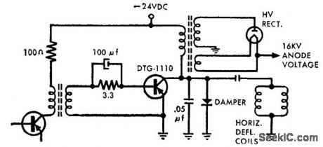
Uses 200-v 15-amp transistor with high power dissipation characteristics and low thermal resistance. Drive requirements are substantially reduced because transistor has high saturated current gain.-High-Power Nu-Base Germanium Transistors (Delco Radio ad), Electronics, 39:7, p 20-21. (View)
View full Circuit Diagram | Comments | Reading(1144)
BLOOD_PRESSURE_INDICATOR
Published:2009/7/20 20:37:00 Author:Jessie
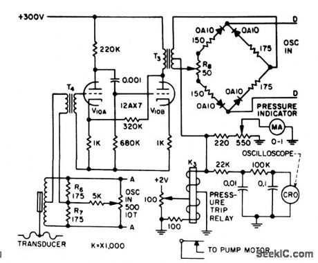
Transducer bridge is energized at points A-A by external 3-kc oscillator. Unbalance voltage is amplified by V10 and demodulated by second bridge that operates as rectifier with phase discrimination, while energized at D-D by separate 3-kc oscillator source. During unbalance, the only components reaching ring demodulator are those in phase or l80° out of phase with reference carrier voltage, giving positive or negative swing on meter-R.Schild and N. Wesson, Servo Circuit Controls Artificial Heart, Electronics, 31:15, p 73-75. (View)
View full Circuit Diagram | Comments | Reading(1170)
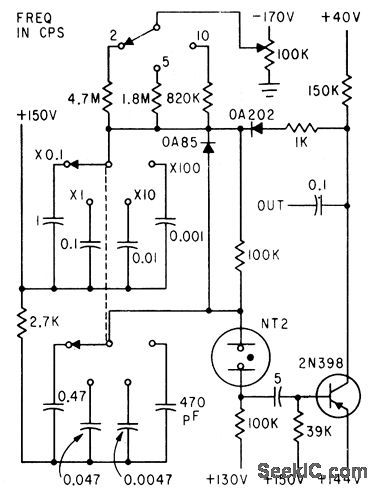
CAPACITIVE_TRANSISTOR_SYNC_LOCK
Published:2009/7/20 20:36:00 Author:Jessie
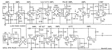
Provides stable sync lock of signal generator against noise interference on tv station relay lines.-Y. Fujimura and N. Mii, Automatic Frequency Control with Reactance Transistors, Electronics, 33:40, p 97-99. (View)
View full Circuit Diagram | Comments | Reading(1525)
EEG_WAVEFORM_ZERO_DETECTOR
Published:2009/7/20 20:34:00 Author:Jessie
Uses Schmitt triggers to produce output of one value when input signal exceeds preset reference, and produces output of one other value when input signal is less than reference value.-C. J. Zaander, Computer Analyzes Brain Waveforms, Electronics, 31:29, p 68-72. (View)
View full Circuit Diagram | Comments | Reading(1226)
MESA_TRANSISTOR_TUNER_OSCILLATOR
Published:2009/7/20 20:34:00 Author:Jessie
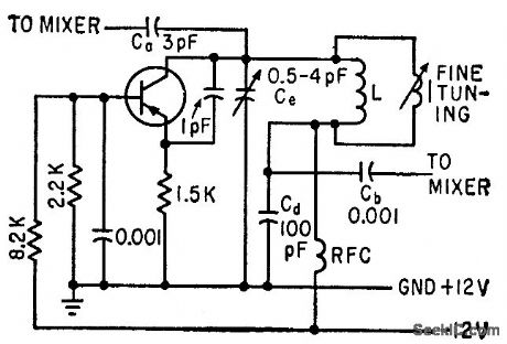
Uses common-base transistor connection, which is regenerative at high frequencies. Additional feedback capacitance between emitter and collector assures dependable oscillation. With emitter current of 2 ma, circuit can supply about 20 times the 300 microwatts required by mixer. Sliding-core coil gives 2:1 change in inductance for fine tuning.-H. F. Cooke, Designing Tv Tuners with Mesa Transistors, Electronics, 33:15, p 64-69. (View)
View full Circuit Diagram | Comments | Reading(782)
THREE_OUTPUT_3_KC_OSCILLATOR
Published:2009/7/20 20:34:00 Author:Jessie
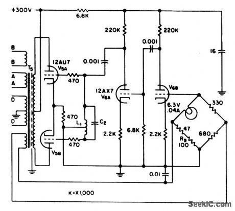
L-C oscillator provides carrier voltages of 4 V rms at 3 kc to blood-volume servo amplifier and to venous and arterial pressure indicator-Amplitude stabilization is achieved by bridge feedback network using filament-type lamp as nonlinear element in one bridge arm.-R. Schild and N. Wesson, Servo Circuit Controls Artifidal Heart, Electronics, 31:15, p 73-75. (View)
View full Circuit Diagram | Comments | Reading(797)
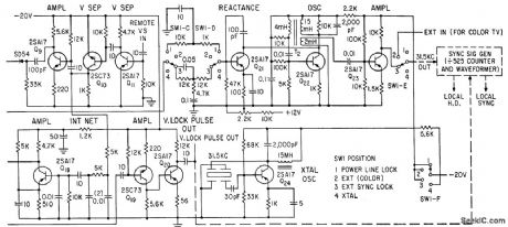
INDUCTIVE_TRANSI_STOR_SYNC_LOCK
Published:2009/7/20 20:33:00 Author:Jessie
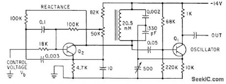
D-c bias of inductive-reactance transistor Q2 is controlled by modulating voltage from oscillator Q1.-Y. Fujimura and N. Mil, Automatic Frequency Control with Reactance Transistors, Electronics, 33:40, p 97-99. (View)
View full Circuit Diagram | Comments | Reading(766)
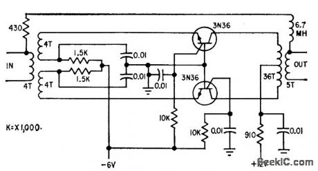
CCTV_10_MC_REPEATER
Published:2009/7/20 20:31:00 Author:Jessie
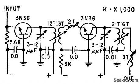
Has gain characteristics to match losses in 0.5 mile of coaxial cable. Mismatching is used at input and between stages to stabilize gain and cut if down to required 18 db at 15 Mc.-L. G. Schimpf, Carrier Transmission for Closed-Circuit Television, Electronics, 32:24, p 66-68. (View)
View full Circuit Diagram | Comments | Reading(764)
ULTRASONIC_OSCILLATOR_KEYER
Published:2009/7/20 20:31:00 Author:Jessie
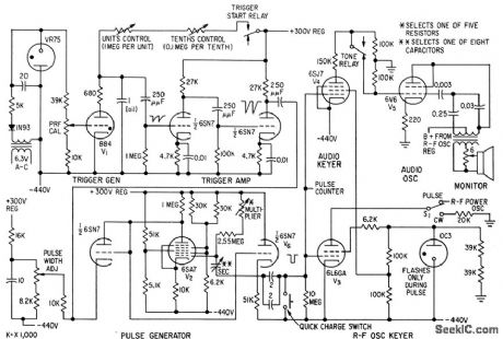
Generates keying pulses up to 2 sec wide at prf down to 0.1 pps. Oscillator cutoff bias is gated off during pulse operation and switched off during c-w operation. Pulse repetition generator V1 is relaxation oscillator with trigger period variable in 0.1-sec steps from 0.1 to 10.9 sec. Fast-recovery phantastron pulse generator 1/2 allows precise pulsing up to 90% duty cycle, with pulse lengths from 0.005 to 2 sec.-B. J. Cosman amd T. F.Hueter, Instrumentation for Ultrasonic Neurosurgery, Electronics, 32:20, p 53-57. (View)
View full Circuit Diagram | Comments | Reading(950)
CCTV_RECEIVING_TERMINAL
Published:2009/7/20 20:31:00 Author:Jessie
Used with repeater (not shown) that makes up for loss in last section of cable. Amplifier then raises level about 10 db. Selective negative feedback improves transmission characteristic over bandwidth of 3 to 17 Mc.-L. G. Schimpf, Carrier Transmission for Closed-Electronics, Television, Electronics 32:24, p 66-68.
(View)
View full Circuit Diagram | Comments | Reading(709)
LASER_TV
Published:2009/7/20 20:30:00 Author:Jessie
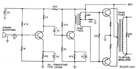
Audio driver delivers 300 v peak. to peak to KDP optical modulator controlling gas laser.-C. J. Peters et al., Laser-Television System Developed With Off-The Shelf Equipment, Electronics, 38:3, p 75-78.
(View)
View full Circuit Diagram | Comments | Reading(902)
OSTEOGRAPH_DETECTS_BONE_DISEASE
Published:2009/7/20 20:26:00 Author:Jessie
Electronic scanner using television fiying-spot microscope measures irregular micro-scopic tissue areas of spongy bone, for earlydiagnosis of bone disease. Television moni-tor receiver shows enktrged picture of bone section as ctid in centering areo to be scanned. Recorder plots ratio between bonearec and marrow area.-0. W. Jones III, R. V. Vreelcmd, and C. C. Collins, Video Microplanimeter Detects Bone Disease, Flee.tronics, 31:43, p 85-87. (View)
View full Circuit Diagram | Comments | Reading(1310)
TRIGGER_SHAPING_FOR_RETINA_WELDER
Published:2009/7/20 20:23:00 Author:Jessie
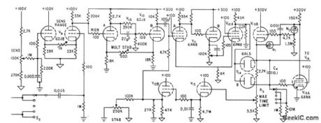
Trigger pulse, selected by S2, is compared to fixed bias on one half of comparator tube V9. Trigger shaping by V10 provides strong, sharp pulse for gating mvbr V11-V12A, which turns off diodes V14, allowing Miller integrator V13A and cathode follower V13B to start lime base runup that drivesC4 to 150V. Circuit then reverts to normal.-O. Rich, Jr. and R. V. Hill, R-F Spot Welder Reattaches Retina of Human Eye, Electronics,34:32, p 160-163. (View)
View full Circuit Diagram | Comments | Reading(792)
MYOELECTRIC_STIMULATOR
Published:2009/7/20 20:47:00 Author:Jessie
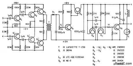
Six-transistor amplifier having high-impedance differential input for commercial eeg or emg electrodes and gain of 10,000 from 5 to 10,000 cps drives modulator Q4-Q5 from decoupling transformer. Modulator makes stimulator (astable mvbr Q6-Q7) apply pulsating voltages to muscles of hand, to make hand open in response to signals picked up by electrodes ovel shoulder muscles, thereby bridging severed arm nerves.-L Vodovnik and W. D. McLeod, Electronic Detours of Broken Nerve paths,Electronics,38:19,p110-116. (View)
View full Circuit Diagram | Comments | Reading(3048)
BLOOD_PRESSURE_REGULATOR
Published:2009/7/20 20:46:00 Author:Jessie
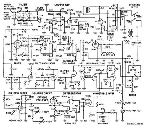
Chopper amplifier delivers d-c voltage to adder that is proportional to mean blood pressure. Potentiometers in adder permit introducing negative voltages corresponding to desired blood pressure level and maximum safe level-R. L. Skinner, D. K. Gehmlich, and F. W. Longson, Blood Pressure and Heart Regulator, Electronics, 32:1, p 38-41. (View)
View full Circuit Diagram | Comments | Reading(1014)
RETINA_STIMULATOR
Published:2009/7/20 20:43:00 Author:Jessie
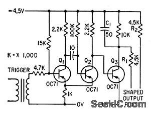
Generated pulse is op plied to skin near eyes, to act on nerve cells of retina and give same effect as slight flash of extremely short duration.-P. Scott, Microflash and Pulse Stimulator Tests Human Optical Response, Electronics, 34:27, p 48-51. (View)
View full Circuit Diagram | Comments | Reading(705)
| Pages:28/126 At 202122232425262728293031323334353637383940Under 20 |
Circuit Categories
power supply circuit
Amplifier Circuit
Basic Circuit
LED and Light Circuit
Sensor Circuit
Signal Processing
Electrical Equipment Circuit
Control Circuit
Remote Control Circuit
A/D-D/A Converter Circuit
Audio Circuit
Measuring and Test Circuit
Communication Circuit
Computer-Related Circuit
555 Circuit
Automotive Circuit
Repairing Circuit