
Electrical Equipment Circuit
Index 39
Color_TV_chroma_processing_system_with_a_PLL_featuring_APC_and_ACC
Published:2009/7/21 6:15:00 Author:Jessie
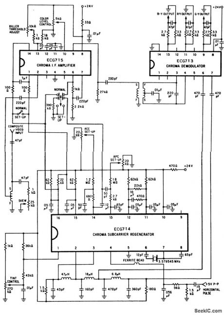
Color TV chroma processing system with a PLL featuring APC and ACC (courtesy GTE Sylvania Incorporated). (View)
View full Circuit Diagram | Comments | Reading(832)
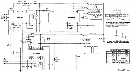
Color_TV_automatic_resolution_control_1
Published:2009/7/21 7:44:00 Author:Jessie
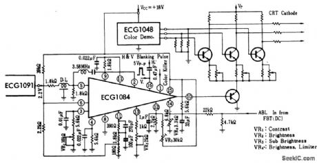
Color TV automatic resolution control. The ECG1091 partially shown is for reference only and is a videp processor chip (courtesy GTE Sylvania Incorporated). (View)
View full Circuit Diagram | Comments | Reading(697)
TV_sound_channelwith_1_watt_output
Published:2009/7/21 7:41:00 Author:Jessie
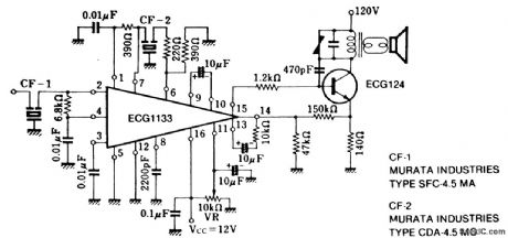
TV sound channelwith 1-watt output. The ECG1133 containsthree IF differential dmplifiers, a phase detector, a DC operated volume control and an AF amplifier. The IF specified is 4.5 MHz (courtesy GTE Sylvania Incorporated). (View)
View full Circuit Diagram | Comments | Reading(690)
LOW_POWER_PARALLEL_TRANSISTOR_OUTPUT
Published:2009/7/21 7:41:00 Author:Jessie
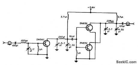
Conventional transistor arrangement provides up to 2 w output with power gain of 10 db. Chief advantage is simplicity.-W.A. Rheinfelder, Choosing the Best Transmitter Output Stage, EEE, 11:10, p 48-53. (View)
View full Circuit Diagram | Comments | Reading(911)
Color_TV_chroma_demodulator_with_tint_control
Published:2009/7/21 7:39:00 Author:Jessie
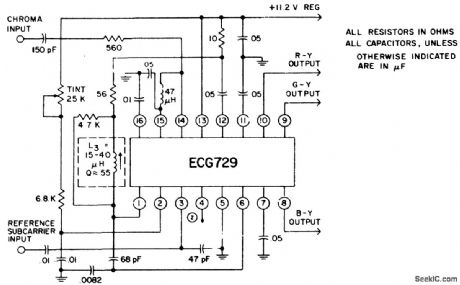
Color TV chroma demodulator with tint control. The color demodulators consist of two sets of balanced detectors that receive their reference subcarrier from the internal demodulator drive amplifiers. The chroma signal input is applied to pin 14. The chroma signal differentially drives the demodulators. The demodulation components are matrixed and DC-shifted in voltage to give R-Y, G-Y and B-Y color difference compo-nents with close DC balance and proper amplitude ratios. When the zener reference element is not used the power supply should be maintained at +11.2 volts (courtesy GTE Sylvania Incorporated). (View)
View full Circuit Diagram | Comments | Reading(1338)
Low_noise_TV_IF_system_with_two_FET_amplifiers
Published:2009/7/21 6:59:00 Author:Jessie
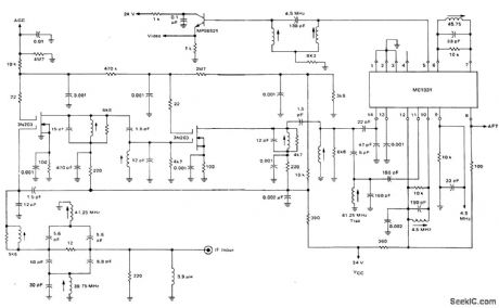
Low-noise TV IF system with two FET amplifiers (courtesy Motorola Semicon,-ductor Products Inc.). (View)
View full Circuit Diagram | Comments | Reading(926)
Color_TV_chroma_processor_using_an_ECG797_16_pin_QIP_with_AFPC_ACC_andkiller
Published:2009/7/21 6:52:00 Author:Jessie
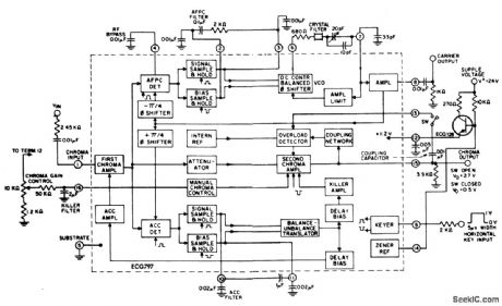
Color TV chroma processor using an ECG797 16-pin QIP with AFPC, ACC, andkiller (courtesy GTE Sylvania Incorporated). (View)
View full Circuit Diagram | Comments | Reading(807)
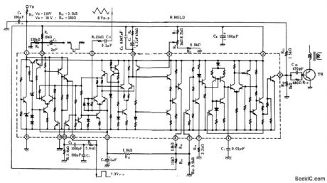
TV_horizontal_AFC_and_oscillator_with_sync_separator_for_negative_sync_using_an_ECG1086_16_pin_DIP
Published:2009/7/21 6:46:00 Author:Jessie
TV horizontal AFC and oscillator with sync separator for negative sync, using an ECG1086 16-pin DIP. The singletransistor stage is the horizontal driver and can be an ECG199 bipolar transistor (courtesy GTE Sylvania Incorporated). (View)
View full Circuit Diagram | Comments | Reading(1017)
TV_horizontal_AFC_and_oscillator_with_sync_separator_for_positive_sync_using_an_ECG1086_16_pin_DIP
Published:2009/7/21 6:43:00 Author:Jessie
TV horizontal AFC and oscillator with sync separator for positive sync, using an ECG1086 16-pin DIP. The single transistor shown is an ECG199, a horizontal driver stage (courtesy GTE Sylvania Incorporated). (View)
View full Circuit Diagram | Comments | Reading(1312)
TV_video_IF_amplifier_video_detector_and_signal_processor_circuits_Used_in_color_and_BW_TVs
Published:2009/7/21 6:26:00 Author:Jessie
TV video IF amplifier, video detector, and signal processor circuits. Used in color and B&W TVs (courtesy GTE Sylvania Incorporated). (View)
View full Circuit Diagram | Comments | Reading(1734)
TELEPHONE_TAP
Published:2009/7/7 22:55:00 Author:May
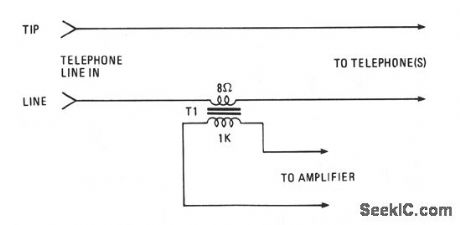
Amplify or record a telephone call with the simple circuit shown. The 8-Ω secondary winding of a min-iature transistor output transformer is connected in series with either of the telephone lines. The 1000-Ω primary winding can feed either a cassette recorder or an audio amplifier. (View)
View full Circuit Diagram | Comments | Reading(940)
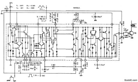
TV45_MHz_sound_channel_with_1__wattAF_output_using_an_ECG1051_chipand_an_ECG171_bipolartransistor
Published:2009/7/21 7:24:00 Author:Jessie
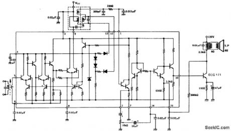
TV4.5 MHz sound channel with 1 -wattAF output using an ECG1051 chipand an ECG171 bipolartransistor. Typical supply voltage for the chip is 10 g volts, while the output transistor can be operated from a 120-volt DC supply. Audio output from the chip is 3 volts RMS. The IF transfomen radio detector transformer and audio output transfomer are all standard and can be purchased at Radio Shack(courtesy GTE Sylvania Incorporated).
(View)
View full Circuit Diagram | Comments | Reading(811)
ColorTV_358_MHz_crystal_oscillator_using_a_dual_gate_MOSFET
Published:2009/7/21 7:19:00 Author:Jessie
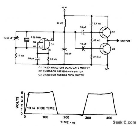
ColorTV 3.58 MHz crystal oscillator using a dual-gate MOSFET (courtesy Texas Instruments Incorporated). (View)
View full Circuit Diagram | Comments | Reading(1497)
Color_TV_automatic_resolution_control
Published:2009/7/21 7:17:00 Author:Jessie
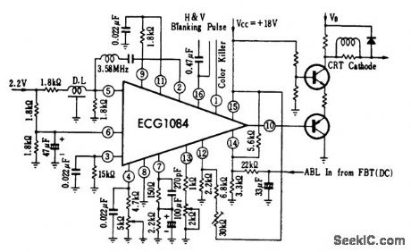
Color TV automatic resolution control (courtesy GTE Sylvania Incorporated). (View)
View full Circuit Diagram | Comments | Reading(759)
TV_video_signal_processor_circuit_1
Published:2009/7/21 7:32:00 Author:Jessie
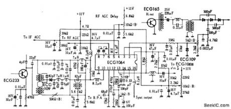
TV video signal processor circuit. The ECG1064 chip contains a first video amplifier, two sync pulse amplifiers, look-out protector, noise detector, two noise gates, AGC detector, IF AGC amplifier, BF AGC delay clamp, RF AGC amplifier, beam current limiter and syncpulse separator (courtesy GTE Sylvania Incorporated). (View)
View full Circuit Diagram | Comments | Reading(2045)
The_ECG_1064_chip
Published:2009/7/21 7:29:00 Author:Jessie
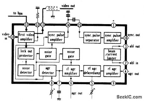
The ECG 1064 chip(see page 651).
(View)
View full Circuit Diagram | Comments | Reading(720)
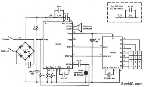
PULSE_DIALING_TELEPHONE
Published:2009/7/7 21:36:00 Author:May

The TP5700 or TP5710 can reduce the number of components required to build a pulse-dialing telephone, as shown. The usual current source can be eliminated by using the VREG1 output to power a TP50982A low-voltage (1.7 V) pulse dialer via a blocking diode. A low forward-voltage drop diode such as a Schottky type is necessary because VREG1 is used in its nonregulated mode and its output voltage might fall to 2 V on a 20-mA loop. A 100-μF decoupling capacitor is required to hold up the pulse dialer supply voltage during dialing. This capacitor will take about one second to charge up when the telephone is first connected to the line, but thereafter, the 20-MΩ resistor, required to retain the last-number dialed memory, will keep this capacitor charged. Partial muting is obtained by directly connecting the N-channel opendrain mute output of the pulse dialer to the RCV in pin on the speech circuit. A fully muted pulse dialer design requires the use of a shunt-mode dialer, such as the TP50981A or TP50985A. (View)
View full Circuit Diagram | Comments | Reading(3284)
Color_TV_AFT_circuit
Published:2009/7/21 7:28:00 Author:Jessie
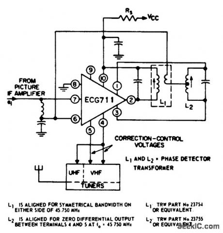
Color TV AFT circuit. The supply is +30 volts, resistor Rs is 1.5K, the bypass capacitor between pin 10 and ground is 0.001 μF, the capacitor across L1 is 91 pF, the capacitor across L2 is 68 pF, the series coil and capacitor at pins 6 and 7 are 3.3 μH and 0.001 μF and the input frequency at 45.75 MHz (courtesy GTE Sylvania Incorporated). (View)
View full Circuit Diagram | Comments | Reading(953)
TONE_DIALING_TELEPHONE
Published:2009/7/7 21:11:00 Author:May
This circuit shows the TP5700 directly interfacing to a low-voltage DTMF generator.VREG1 supplies the necessary 2-V minimum bias to enable the TP5380 to sense key closures and pull its mute output high.VREG1 then switches to a 3-V regulated output to sustain the tone dialer during tone generation. The TP5700 DTMF input incorporates the necessary load resistor to V- and provides gain, plus AGC action, to compensate for loop length. A muted tone level is heard in the receiver. For DTMF generators with a higher output level than the TP5380, a resistive potentiometer should be added to reduce the level at the speech circuit DTMF input. (View)
View full Circuit Diagram | Comments | Reading(4654)
HANDS_FREE_TELEPHONE
Published:2009/7/7 20:55:00 Author:May
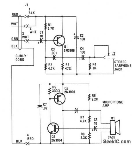
Transistor Q1 of the headset amplifier circuit amplifies the 30 mV signal, that would have gone to the earphones, to.5 V, which sufficiently drives the stereo earphones. Capacitor C1 blocks any dc current from shorting back into the telephone base. Capacitor C2 provides the very important ac signal short around the amplifier. Capacitor C3 provides high-frequency rolloff characteristics and prevents the amplifier from oscillating. Capacitor C4 is a dc block to the 35-Ω impedance of the stereo earphones, and resistor R4 bleeds off any charge build up to prevent a popping sound when the stereo earphones are plugged into the mini-earphone jack J2. The headset amplifier has only about 2 Vdc across it. The microphone amplifier circuit is composed of transistors Q2 and Q3 in an inverted-Darlington configuration.Another, and perhaps easier, way to understand the operation of this circuit is to consider Q3 as an emitter-follower stage. The electret microphone has a built-in FET IC amplifier that needs at least 3 V at 0.4 mA of clean supply power in order to provide an output impedance of 200 to 800 Ω. Resistors R6 and C5 provide that clean dc power to the FET IC and also provide the bias to Q2 without an ac feedback, which would have reduced Q2's gain. Capacitor CG blocks the output dc bias from the FET IC. (View)
View full Circuit Diagram | Comments | Reading(1134)
| Pages:39/126 At 202122232425262728293031323334353637383940Under 20 |
Circuit Categories
power supply circuit
Amplifier Circuit
Basic Circuit
LED and Light Circuit
Sensor Circuit
Signal Processing
Electrical Equipment Circuit
Control Circuit
Remote Control Circuit
A/D-D/A Converter Circuit
Audio Circuit
Measuring and Test Circuit
Communication Circuit
Computer-Related Circuit
555 Circuit
Automotive Circuit
Repairing Circuit