
Electrical Equipment Circuit
Index 22
RP-type ideal diode circuit
Published:2011/8/7 23:40:00 Author:Sophia | Keyword: RP-type, ideal diode
Clamping circuit is difficult to achieve in non-inverting idealized diode circuit. Inevitably the output can be saturated on the negative potential. Thus, the general idealized diode is constituted by the inverting circuit shown in Figure 1. In this circuit, when the input is positive potential, diode D1 is conducted, and OP amplifier output is almost saturated because of the diode forward voltage (-VF). At this point, because of -VF, the diode D1 is against the bias, and the circuit output resistance ro is 10kΩ. (View)
View full Circuit Diagram | Comments | Reading(819)
The symmetrical double T circuit to improve the notch filter circuit
Published:2011/8/7 23:40:00 Author:Sophia | Keyword: symmetrical double T, improve the notch filter
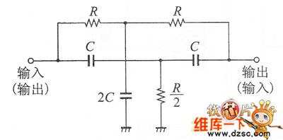
Figure 1 is an example of the symmetrical double-T circuit. Under careful observation, we found that it is circuit synthesis of low-pass filter and high pass filter. In this circuit, usually the ratio of components grounding into the earth adopts 2C and R / 2 method. The reason for this is that the ratio can effectively make the attenuation frequency reach the spike values, but the Q value of this circuit is also dropped to 0.25, zero frequency The composition of the circuit is extremely simple, accoring to the circuit, we can see 2C capacitors is needed. The author's approach improves the cost, we can adopt two capacitors connected in parallel to process. (View)
View full Circuit Diagram | Comments | Reading(2607)
The RC phase-shift circuit with unchanged Output amplitude
Published:2011/8/7 23:42:00 Author:Sophia | Keyword: The RC phase-shift circuit, unchanged Output amplitude
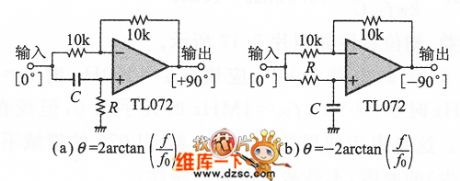
The most commonly used phase shifter phase difference is 90 °. Shown in Figure 1, in the RC phase shift circuit, even the amplitude is allowed down to 3dB, phase shift quantity is 45 °, as in the OP amplifier circuit shown in Figure 1, which is characterized by the phase shift of 0 to 180 °, 180 °to 0 , and the output amplitude does not depend on input frequency. The diagram shows the basic of RC phase circuit, the inverting amplifier of the gain A =- 1. This RC circuit can be connected to the non-inverting input terminal to decide the feedback resistance of inverting gain. If they are the same resistance value, its value can be chosen freely, actually, it is typically chosen to be 10kΩ. (View)
View full Circuit Diagram | Comments | Reading(3755)
High-voltage Electrostatic Generator (the 1st)
Published:2011/7/29 4:32:00 Author:Felicity | Keyword: High-voltage Electrostatic, Generator
Work of the circuit
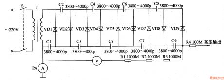
The circuit consists of power Switch power transformer T, rectifier diode VDl-VD9, capacitors Cl-C9, resistors R1-R4, a voltmeter PV and ammeter PA. (It is showed in the picture 8-115.)
Turn on power switch s. the 220V AC voltage is set-up by the power transformer. The 9 doubler rectifying circuit consists of VDl-VD9 and Cl-C9. The voltage is 9 doubler rectified by the circuit. It then produces 100LV DC voltage. The voltage separates into two parts. One is limited by M and then outputted. The other one is limited by R1-R3. PV shows the value of outputting voltage.
When the circuitcomponentsinstalled,you should useepoxytosealfillingprocessto preventdischargebetweenthe variouscomponents. (View)
View full Circuit Diagram | Comments | Reading(6100)
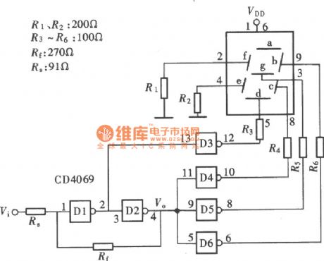
Logic Pen-based Text Display Formed With The Gate Circuit The 3rd (CD4069) Circuit
Published:2011/8/6 8:46:00 Author:Felicity | Keyword: Logic Pen-based Text Display, The Gate Circuit
View full Circuit Diagram | Comments | Reading(1355)
irrigation motor automatic protector (1)
Published:2011/7/20 0:30:00 Author:chopper | Keyword: irrigation motor, automatic protector
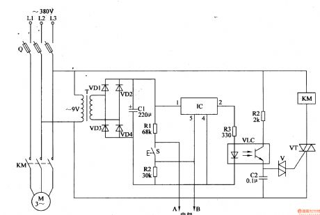
The principle of circuitThe irrigation motor automatic protector circuit is formed by the power supply circuit and the detection/protection control circuit, which is shown in Figure 4-96. Power supply circuit is formed by the power transformer T, rectifier diodes VD1-VD4 and filter capacitor C1. Detection/protection control circuit is formed by the detection electrodes A,B,start button S,resistors R1-R4, capacitor C2, optical coupler VLC, bi-directional trigger diode V, thyristor VT, electronic switch integrated circuit IC and AC contactor KM.
(View)
View full Circuit Diagram | Comments | Reading(1564)
Digital lock 6
Published:2011/8/8 2:26:00 Author:Ecco | Keyword: Digital lock
The digital lock circuit is composed of the power switch SO, power transformer T, bridge rectifier UR, relays Kl, K2, password buttons Sl-Sl2, transistors VT, LED VLl, VL2, diodes VD1-VD4, resistors R1 -R3 and capacitors Cl-C6, and it is shown in Figure 3-103. Rl-R3 use the 1/4W carbon film resistors or metal film resistors. Cl-C4 select ultra small aluminum electrolytic capacitors with the voltage in 16V; C5 uses the monolithic capacitor. VD1-VD4 are choose 1N4148 silicon switch diode; VD5 uses the lN4007 silicon rectifier diode.
(View)
View full Circuit Diagram | Comments | Reading(896)
Digital lock 5
Published:2011/8/8 2:21:00 Author:Ecco | Keyword: Digital lock
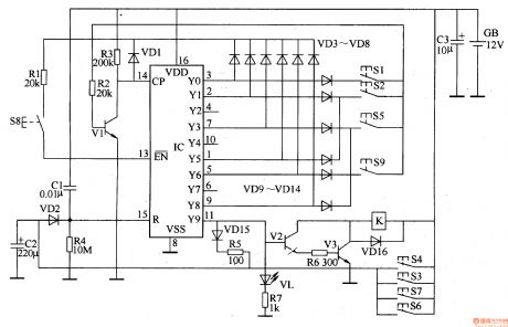
The digital lock circuit is composed of the input control circuit, reset circuit, counter / divider circuit and control implementation circuit, and it is shown in Figure 3-102. The input control circuit is composed of password buttons S1, S2, S5, S8, S9 and diodes VD3-VDl4, resistor R1 and so on. Count / divider circuit consists of IC and transistor Vl, resistors R2, R3, diode VDl. Reset circuit consists of capacitors Cl, C2, diodes VD2, VDl5, resistors R4, R5 and buttons S3, S4, S6, S7. Control implementation circuit is composed of transistors V2, V3, light-emitting diode VL, resistors R6, R7, relay (or electric lock) K and diode VDl6.
(View)
View full Circuit Diagram | Comments | Reading(1474)
Digital lock 4
Published:2011/8/8 2:16:00 Author:Ecco | Keyword: Digital lock
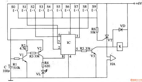
The digital lock circuit is composed of the timing trigger circuit, trick lock circuit, sound and alarm circuit and control implementation circuit, and it is shown in Figure 3-101. Timing trigger circuit is composed of the transistors Vl, V2, resistors Rl-R4, light-emitting diode VL and capacitor C. The trick lock circuit is composed of the password buttons S0-S9 and electronic lock integrated circuit IC. Sound and alarm circuit is composed of resistor R6, thyristor VT and alarm HA. Control implementation circuit is composed of the resistor, transistor V3, relay K (or electric locks), and diode VD.
(View)
View full Circuit Diagram | Comments | Reading(2271)
Digital lock 3
Published:2011/8/8 3:39:00 Author:Ecco | Keyword: Digital lock
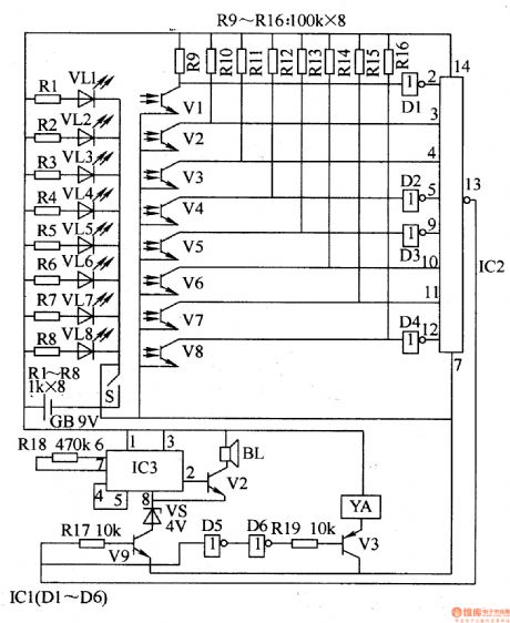
The digital lock circuit consists of the optical switch circuit, trigger, sound and alarm circuit and solenoid drive circuit, and it is shown in Figure 3-100. Photoelectric switch circuit consists of the light-emitting diodes VLl-VL8, phototransistors Vl-V8 and resistors Rl-R16. Trigger circuit consists of the Dl-D4 which are inside of six NOT gate integrated circuit ICl (Dl-D6) and eight-input NAND gate IC lC2. Sound and alarm circuit is composed of the integrated circuit IC3, transistors V9, VlO, voltage regulator diode VS, speaker BL and resistors R17, Rl8.
(View)
View full Circuit Diagram | Comments | Reading(1371)
Digital lock 2
Published:2011/8/8 3:36:00 Author:Ecco | Keyword: Digital lock

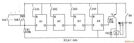
The digital lock circuit consists of buttons S1-S10 (S1-S4 are valid password buttons, S5-S10 are the lock buttons), four RS trigger integrated circuit IC (Al-A4) and resistor Rl. Control implementation circuit is composed of the resistor R2, transistor V, Relay K and diode VD. Rl and R2 use the 1/4W carbon film resistor or metal film resistor. VD selects the lN4001 or 1N4007 silicon rectifier diode. V uses C8550 or S8550, 3CG8550 silicon PNP transistor. IC choosed the CC4043 CD4043 four-RS flip-flop circuit. S0 uses the ordinary power switch.
(View)
View full Circuit Diagram | Comments | Reading(1612)
Digital lock 1
Published:2011/8/8 3:33:00 Author:Ecco | Keyword: Digital lock
The digital lock circuit is composed of the password input control circuit, error closed circuit, reset circuit and control implementation circuit, and it is shown in Figure 3-98. Password input control circuit consists of the buttons Sl-S4, transistors V3-V5, voltage regulator diodes VSl-VS3, resistors R3-R7 and capacitors C2-C4. Error closed circuit is composed of the buttons S6-S10, capacitor Cl, voltage regulator diode VS5, transistors Vl, V2 and resistor Rl. Control implementation circuit is composed of the transistors V6-V8, relay K, diode VD, voltage regulator diode VS4, resistors R9-Rl2 and capacitors C5, C6.
(View)
View full Circuit Diagram | Comments | Reading(802)
Digital lock 8
Published:2011/8/8 3:18:00 Author:Ecco | Keyword: Digital lock
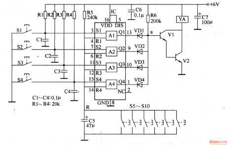
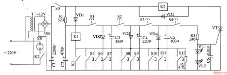
The digital lock circuit is composed of the password input control circuit and control implementation circuit, and it is shown in Figure 3-105. Password input control circuit is composed of the password buttons S1-S10 (S1-S4 are valid passwords, S5-S10 are invalid passwords), R-S flip-flop IC lC, resistors R1-R5 and capacitors Cl-C5. Control implementation circuit consists of the diodes VDl-VD4, resistor R6, transistors Vl, V2, and solenoid YA. C6 and C7 use the power filter capacitors. Rl-R6 select the 1/4W carbon film resistors or metal film resistors.
(View)
View full Circuit Diagram | Comments | Reading(2804)
Digital lock 9
Published:2011/8/8 3:21:00 Author:Ecco | Keyword: Digital lock
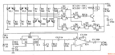
The digital lock circuit is composed of the light control coding circuit, logic control circuit, control implementation circuit and alarm, and it is shown in Figure 3-106. Light control coding circuit consists of the infrared light emitting diodes VLl-VM, infrared receiver photodiodes VDl-VD4 and resistors Rl-R8. Logic control circuit consists of NAND gate integrated circuit ICl (Dl. D4) and the OR gate integrated circuit IC2 (D5-D7). Control implementation circuit is composed of the transistor V, resistor R9, diode VD5 and relay K. Voice alarm circuit is composed of the integrated circuit IC3, audio power amplifier integrated circuit IC4, voltage regulator diode VS, resistors RlO-R14, capacitors Cl-C6 and the speaker BL.
(View)
View full Circuit Diagram | Comments | Reading(940)
Inductive electronic doorbell 1
Published:2011/8/7 22:52:00 Author:Ecco | Keyword: inductive electronic doorbell
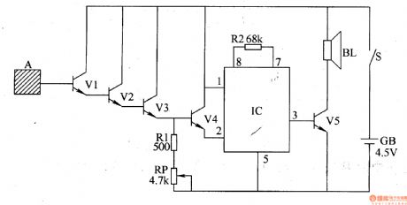
The inductive electronic doorbell circuit is composed of the inductive electronic switch and music generator circuit, and it is shown in Figure 3-115. Inductive electronic switch circuit is composed of the inductive electrode A, transistor Vl-V4 and the resistor R1, potentiometer RP components. Music generator circuit by the music integrated circuit IC, resistor R2, transistor V5 and speaker BL. Rl and R2 select the 1/4W carbon film resistors or metal film resistors. RP chooses the membrane variable resistor. Vl-V3 use 3DG6 or Sg013 silicon NPN transistors; V4 and V5 use C8050 or S8050, 3DG8050, 3DGl2 silicon NPN transistors. IC uses the KD9300 or CW9300 music circuit.
(View)
View full Circuit Diagram | Comments | Reading(3175)
Inductive electronic doorbell 2
Published:2011/8/7 22:56:00 Author:Ecco | Keyword: Inductive electronic doorbell
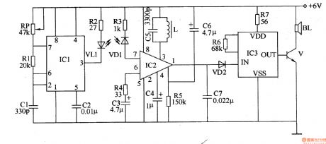
The inductive electronic doorbell circuit is composed of the infrared transmitter, infrared receiver circuit and music generating circuit, ans it is shown in Figure 3-116. Infrared transmitter circuit consists of the time-base integrated circuit lCI, infrared light-emitting diode VL, resistors Rl, R2, capacitors Cl, C2 and potentiometer RP. Infrared receiver circuit consists of the infrared photodiode VDl, resistors R3-R5, capacitors C3-C5 , inductor L and infrared receiving and dealing the integrated circuit IC2. Music generating circuit is composed of the music IC IC3, resistors R6, R7, diode VD2, capacitor C7, transistor V, and the speaker BL.
(View)
View full Circuit Diagram | Comments | Reading(1943)
Inductive electronic doorbell 3
Published:2011/8/7 23:05:00 Author:Ecco | Keyword: Inductive electronic doorbell

The inductive electronic doorbell circuit is composed of the trigger control circuit and audio output circuit, and it is shown in Figure 3-117. Trigger control circuit consists of pyroelectric infrared detection module lCl, doorbell circuit IC2, resistors Rl-R4 and capacitors Cl, C2. Audio output circuit consists of transistors Vl, V2, resistor R5 and speaker BL. Rl-R5 use the metal film resistors or carbon film resistors. Cl and C2 select the aluminum electrolytic capacitors with the voltage value being greater than 6V. Vl uses the S9013 or 3DG6 NPN transistor; V2 uses the C8550 or S8550 silicon PNP transistor.
(View)
View full Circuit Diagram | Comments | Reading(1252)
Password electronic doorbell 1
Published:2011/8/8 1:52:00 Author:Ecco | Keyword: Password electronic doorbell

The password electronic doorbell circuit is composed of the electronic password circuit and music occurred circuit, and it is shown in Figure 3-118. Electronic password circuit consists of integrated circuits lCl and keys Sl-S6, diodes VDl-VD5. lCl is the electronic password IC, its pin 1-3 and pin 6 are the effective transmission input ends, and pin 7 is the reset end, when the pin 1, 2, 3, 6 are input high trigger level in turn, only pin 5 outputs high. Otherwise, pin 5 is in low level. R uses the 1/4W carbon or metal film resistor. VDl-VD5 select the 1N4148 silicon switch diodes.
(View)
View full Circuit Diagram | Comments | Reading(1914)
Password electronic doorbell 2
Published:2011/8/8 1:58:00 Author:Ecco | Keyword: Password electronic doorbell

The password electronic doorbell circuit is composed of the trigger circuit and music generating circuit, and it is shown in Figure 3-119. Trigger circuit is composed of the buttons S1-S9, four NAND gate Schmitt trigger integrated circuit IC1 and the external RC components. Music generating circuit is composed of the integrated circuits lC2 and 1C3, transistors Vl and V2, diodes VDl-VD3, speaker BL and the RC components. Rl-R9 select the V4W carbon film resistors. CI-C5 select the aluminum electrolytic capacitors with voltage in lOV. VDl-VD4 select the 1N4148 silicon switch diodes. Vl uses S9013 silicon NPN transistor; V2 uses Sg012 silicon PNP transistor.
(View)
View full Circuit Diagram | Comments | Reading(1717)
Flashing electronic doorbell
Published:2011/8/7 22:37:00 Author:Ecco | Keyword: Flashing electronic doorbell
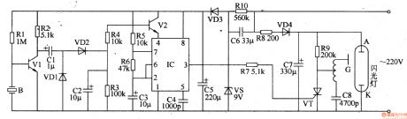
The flashing electronic doorbell circuit is composed of the power supply circuit, audio input trigger circuit, multivibrator, and it is shown in Figure 3-124. The power supply circuit consists of the step-down capacitor C6, resistor RlO, rectifier diode VD3, regulator C5. Audio input trigger circuit s composed of the audio sensor trigger circuit B, transistors Vl, V2, diode VDlR4 and capacitors Cl, C2. Multivibrator is composed of the time-base integrated circuit IC, resistors R5, R6 and capacitors C3, C4. Flash circuit consists of resistors R7-R9, rectifier diode VD4, capacitors C7, C8, thyristor VT and flash components.
(View)
View full Circuit Diagram | Comments | Reading(1133)
| Pages:22/126 At 202122232425262728293031323334353637383940Under 20 |
Circuit Categories
power supply circuit
Amplifier Circuit
Basic Circuit
LED and Light Circuit
Sensor Circuit
Signal Processing
Electrical Equipment Circuit
Control Circuit
Remote Control Circuit
A/D-D/A Converter Circuit
Audio Circuit
Measuring and Test Circuit
Communication Circuit
Computer-Related Circuit
555 Circuit
Automotive Circuit
Repairing Circuit