
Index 226
G52103-the integrated microcomputer circuit of the communication single door
Published:2011/5/12 21:56:00 Author:Borg | Keyword: integrated microcomputer circuit, single door
(View)
View full Circuit Diagram | Comments | Reading(550)
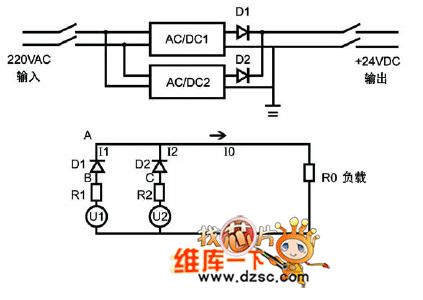
Traditional power system circuit diagram
Published:2011/5/12 21:36:00 Author:Nicole | Keyword: power system
View full Circuit Diagram | Comments | Reading(583)
HA1137W-the FM-IF integrated circuit
Published:2011/5/12 21:38:00 Author:Borg | Keyword: FM-IF, integrated circuit
HA1137W is an FM-IF amplifier integrated circuit produced by Hitachi, Japan, which is used in HI-FI stereo tuner as FM INTREQ.
1. The internal circuit and pin functions of HA1137WHA1137W consists of sub-circuits of INTREQ, orthogonal detection, low noise preamplifier, delay high AGC, step indicator and central indicator. Its features are: high sensitivity of input amplitude, good AM impedence, low harmonic distortion, large working range and without noise in ±50KHz.
HA1137 is in 16-lead dual in-line package.
(View)
View full Circuit Diagram | Comments | Reading(4548)
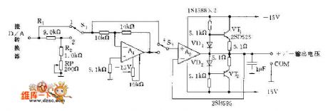
Positive and negative voltage output circuit diagram
Published:2011/5/12 21:45:00 Author:Nicole | Keyword: Positive voltage, negative voltage, output
View full Circuit Diagram | Comments | Reading(670)
S13120C 12V V terminal voltage regulator integrated circuit diagram
Published:2011/5/12 1:44:00 Author:Ecco | Keyword: 12V , V terminal, voltage regulator, integrated circuit
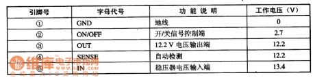
S13120C is the 12V V terminal voltage regulator integrated circuit produced by the micro-systems in the United States, it is widely used in DVD players, televisions, computer monitors, sound system and various kinds of small household appliances in the voltage regulator circuit. 1. Features of functionS13120C IC contains 12V regulated power supply circuit, power supply on / off control circuit, automatic detection circuit and some other ancillary features circuit.2. Pin functions and dataS13120C integrated circuit uses separate 5-pin package, the pin functions and data are listed in Table. S13120C IC pin functions and data
(View)
View full Circuit Diagram | Comments | Reading(711)
5A regulated power supply circuit diagram composed of LM340T integrated regulator
Published:2011/5/12 20:45:00 Author:Ecco | Keyword: 5A , regulated power supply , integrated regulator
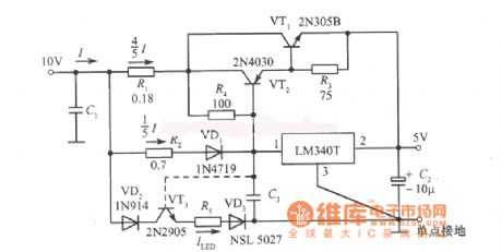
5A regulated power supply circuit diagram(providing power for TTL IC)composed of LM340T integrated regulator
(View)
View full Circuit Diagram | Comments | Reading(1281)
3A regulated power supply circuit diagram composed of LM5000 integrated regulator
Published:2011/5/12 20:46:00 Author:Ecco | Keyword: 3A , regulated power supply , integrated regulator
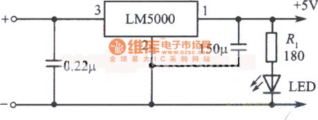
3A regulated power supply circuit diagram(providing power for TTL IC)composed of LM5000 integrated regulator
(View)
View full Circuit Diagram | Comments | Reading(521)
Logic control integrated regulated power supply circuit diagram
Published:2011/5/10 21:41:00 Author:Rebekka | Keyword: Logic control , integrated regulated power supply
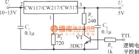
Logic control integrated regulated power supply circuit composed of CW117, CW217 and CW317.
The figure shows the integrated regulated power supply that uses TTL logic level control. When the TTL logic level is high, the transistor VT is saturated. Connect the the resistor R2 to ground, the output voltage is 1.25V. When the logic level is low, the transistor VT will be cut off, the output voltage: Uo = 1.25 (1 + R2/R1) = 5V, the power supply can be used as the logic generator of controlled TTL integrated circuit. (View)
View full Circuit Diagram | Comments | Reading(692)
OTIS TOEC-40 elevator control power supply circuit (1)
Published:2011/5/12 19:39:00 Author:TaoXi | Keyword: OTIS, elevator control, power supply circuit
OTIS TOEC-40 elevator control power supply circuit (1) (View)
View full Circuit Diagram | Comments | Reading(567)
OTIS TOEC-40 elevator control power supply circuit
Published:2011/5/12 19:37:00 Author:TaoXi | Keyword: OTIS, elevator control, power supply circuit
OTIS TOEC-40 elevator control power supply circuit (View)
View full Circuit Diagram | Comments | Reading(579)
BD200W emergency power supply circuit diagram
Published:2011/5/12 1:18:00 Author:Ecco | Keyword: emergency power supply
View full Circuit Diagram | Comments | Reading(643)
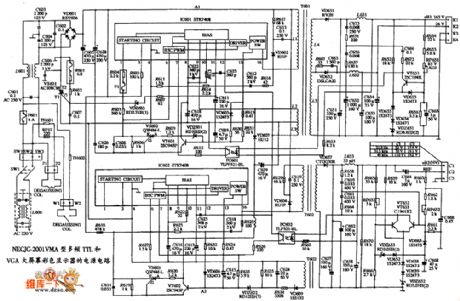
NEC JC-140HM-type VGA Color Display Power Supply Circuit
Published:2011/5/9 22:25:00 Author:Sharon | Keyword: VGA, Color Display, Power Supply
NEC JC-140HM-type VGA Color Display Power Supply Circuit is shown below:
(View)
View full Circuit Diagram | Comments | Reading(587)
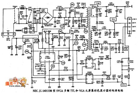
GREAT WALL GW-600C-type V, SVGA Multi-frequency Display Power Supply Circuit
Published:2011/5/9 22:24:00 Author:Sharon | Keyword: V, SVGA, Multi-frequency Display, Power Supply
GREAT WALL GW-600C-type V, SVGA Multi-frequency Display Power Supply Circuit is shown in below figure:
(View)
View full Circuit Diagram | Comments | Reading(787)
Diode Detector Inputting Power circuit
Published:2011/5/9 22:10:00 Author:Sharon | Keyword: Diode Detector, Inputting Power
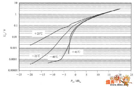
Diode detector inputting power circuit is shown in the figure. This is a simple half-wave rectifier and filter circuit. The circuit's total input resistance is 50Ω.VDis the rectifier, and Cis the filter capacitor. Input power PIN is rectified and filtered to output voltage Uo. The relation curve of Uo and the PIN at different ambient temperatures is shown below. The figure shows that only under the ambient temperature of +25 oC, Uo is approximately in linear relationship with the PIN; when the ambient temperature increases or decreases, Uo will reduce significantly.
(View)
View full Circuit Diagram | Comments | Reading(684)
Color Display EMC EM-1 Type Power Supply Circuit
Published:2011/5/9 22:24:00 Author:Sharon | Keyword: Color Display, Power supply
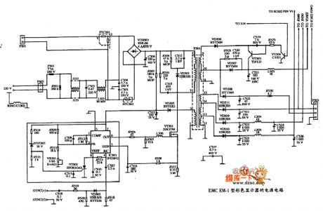
ColorDisplay EMC EM-1 Type Power Supply Circuit is shown in below figure:
(View)
View full Circuit Diagram | Comments | Reading(610)
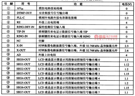
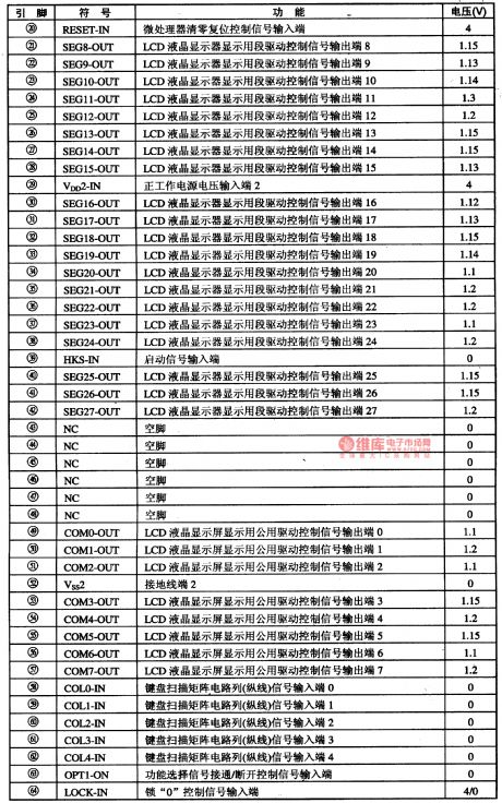
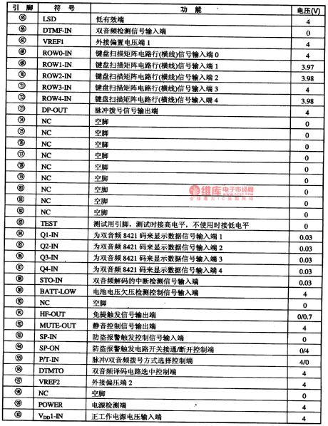
The Decoding Intergrated Circuit of HT9170-DTMF Two-tone Caller Display
Published:2011/5/11 23:59:00 Author:Borg | Keyword: Decoding, Intergrated Circuit, HT9170-DTMF, Two-tone Caller Display
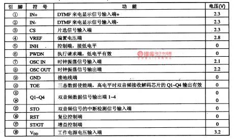
HT9170 is an decoding intergrated circuit of two-tone caller display,which iswidely used in wireless or wiring phones with caller display.
1.pin functions and relevent data
HT9170 intergrated circuits are pinned in dual in-line package with 18-lead, whose pin functions and relevent data are listed in Figure 11.
2.intergrated ciucuits of the same type
The decoding intergrated circuits of caller display usually used by DTMF:CS9370DGP,HM9270C, TH3170D,HM9270D and HT9l70HT9270D. The pin sequences and functions of these 6 circuits are almost the same, and all of their pin functions and relevent data are listed in Table 1-1.
Table 1-1 The pin functions and relevent data of the HT9170 intergrated circuit (View)
View full Circuit Diagram | Comments | Reading(1293)
HICl016-an Intergrated Circuit of Multi-function Power Supplies
Published:2011/5/12 0:04:00 Author:Borg | Keyword: Intergrated Circuit, Multi-function, Power Supplies
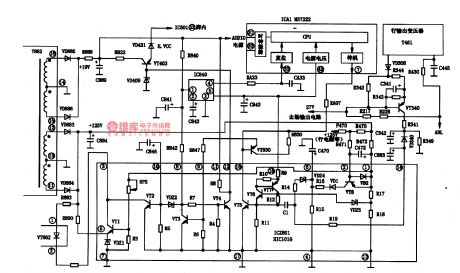
HIC016-is an intergrated circuit of multi-function power supplies used in the switches of TOSHIBA large screen color TV sets.
1.the priciple diagram of the internal circuit
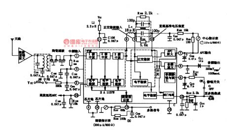
HIC1016 contains sub- protection circuits of power supply fault LEV test of secondary circuits, sampling amplifier, off-hook control and power output, etc, whose internal circuit and typical appolcation circuit are as shown in Figure 1-1.
2.pin functions and data
Pin functions and data of HIC1016 are listed in Table 1-1.
3.typical application circuit
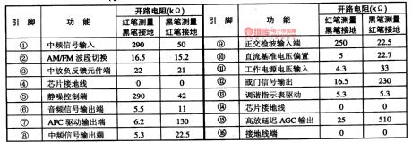
The open loop resistences of HIC1016 are listed in 1-2, which can be used to judge if IC is malfunctioning. The specification data of HIC1016 internal components are listed in 1-3.
Figure 1-1 the internal circuit and typical application circuit of HIC1016
Table 1-1 pin functions and relevent data of HIC1016
Table 1-2 the open loop resistences of HIC1016
Table 1-3 the specification data of HIC1016 internal components
(View)
View full Circuit Diagram | Comments | Reading(1625)
The Battery Charging Control and Alternative Intergrated Circuit of the Bq24700、Bq24701 Laptop
Published:2011/5/11 1:51:00 Author:Borg | Keyword: Battery Charging Control, Alternative Intergrated Circuit
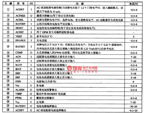
Bq24700、Bq24701 are highly intergrated battery charging control and alternative intergrated circuit specailly developed for laptops which can automatically adjust the charging current by using their DPMs and AC adapters,therefore, the charging time can be shortened, besides, cheap adapters can be installed in it.1.pin functions and relevent dataBq24700、Bq24701 are packaged with pinnings of TSSOP whose pin functions and data are listed in Table 1.
Table 1 pin functions and data of Bq24700
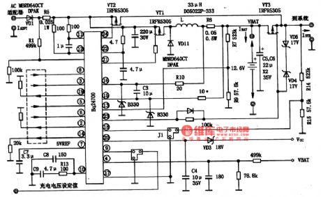
2.typical application circuit The typical application circuit of Bq24700 chips is shown in Figure 1, whose input point connects with the AC adapter and output point with the laptop. VT2 is the adapter alternative switch, and VT3 the battery alternative switch.
Figure 1 The typical application circuit of Bq24700 chips (View)
View full Circuit Diagram | Comments | Reading(3780)
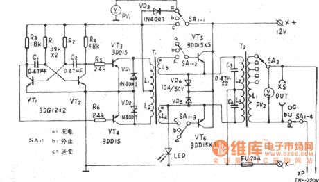
The construction circuit diagram of 0-12V/3A power supply
Published:2011/5/11 22:06:00 Author:Rebekka | Keyword: 0-12V/3A power supply, construction circuit

Usually the power supply can not be adjusted form zero volt. The circuit presented here can be continuously adjusted from 0-12 volts, and the circuit is simple. Its sampling is easy and it is easy to imitate. It is very suitable for amateur electronic enthusiasts to use as experiment power supply. Icon device parameters can use icon value. The transformer should have sufficient capacity according to the output power. (View)
View full Circuit Diagram | Comments | Reading(3200)
5V、0.26A TV standby power supply circuit composed of TNY253P
Published:2011/5/11 22:08:00 Author:Rebekka | Keyword: TV standby power supply
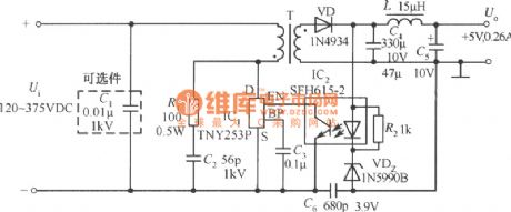
5V、0.26A TV standby power supply circuit composed of TNY253P is shown as above. (View)
View full Circuit Diagram | Comments | Reading(1708)
| Pages:226/291 At 20221222223224225226227228229230231232233234235236237238239240Under 20 |
Circuit Categories
power supply circuit
Amplifier Circuit
Basic Circuit
LED and Light Circuit
Sensor Circuit
Signal Processing
Electrical Equipment Circuit
Control Circuit
Remote Control Circuit
A/D-D/A Converter Circuit
Audio Circuit
Measuring and Test Circuit
Communication Circuit
Computer-Related Circuit
555 Circuit
Automotive Circuit
Repairing Circuit