
Index 240
60v/40mA regulated power supply circuit
Published:2011/4/20 1:18:00 Author:muriel | Keyword: 60v, 40mA , regulated power supply
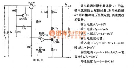
This circuit can prevent short circuit overload by limiting the base current of transistor T1 and output voltage to rated valut via potentiometer R7.
The main technical data:
output voltage:U2=60V
output current:I2=40mA
input voltage:U1=62V~93V
output voltage variable quantity:when output voltage U1=62V~93V(Io=0), ΔU2=20mV; when output current I2=0mA~40mA(U1=constant), ΔU2=5mV; ambient temperature θu=0°C~60°C.
(View)
View full Circuit Diagram | Comments | Reading(1235)
Changing the output voltage of ringing switching power supply circuit diagram
Published:2011/4/22 18:45:00 Author:Nicole | Keyword: switching power supply
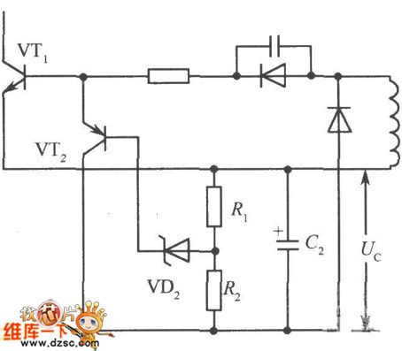
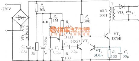
In the ringing choke type switching regulator circuit, the output voltage Uo is in direct proportion to the negative bias Uc, in order to change the output voltage, we should find a way to change Uc, as shown below.
The collector of transistor VT2 is connected on the negative terminal of capacitor C2. Once Uc2 increased, the base current of Zener diode VD2, transistor VT2 also increase, so that VT2 conducting. Because of the collector current VT2 can shorten the conduction time of switching transistor VTl than before, so it can be ended early, then to bring down the output voltage Uo.
(View)
View full Circuit Diagram | Comments | Reading(770)
Circuit diagram of buck-mode converted into boost-mode by CW34603
Published:2011/4/25 4:29:00 Author:Nicole | Keyword: buck-mode, boost-mode
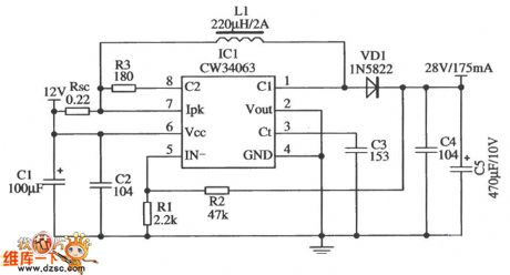
The figure is a typical application circuit of boost-mode. The input voltage is 12 V, output voltage is 28 V/175 mA, it only hasnine external components, the efficiency can reach 90%.
(View)
View full Circuit Diagram | Comments | Reading(504)
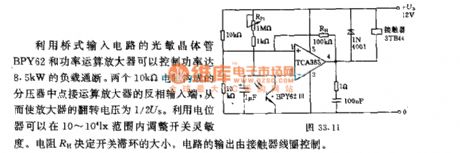
Light intensity control flashing switch circuit
Published:2011/4/24 7:49:00 Author:Nicole | Keyword: light intensity, flashing switch
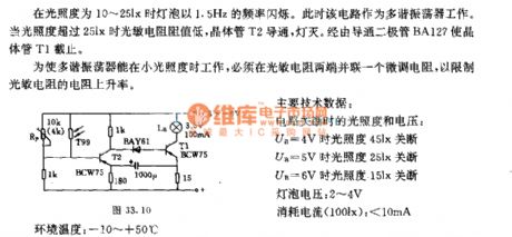
When the light intensity is 10~25lx, the light is flashing with 1.5Hz frequency. At this time, the circuit works as multivibrator. When is light intensity is more than 25lx, the photosensitive resistance is minimum, transistor T2 turns on, the light off. The transistor T1 is cut off by conductive diode BA127.
In order to make the multivibrator can work with low light intensity, it should parallel a trimmer resistor to the sides of photosensitive resistance, then to limit its resistance rate of rise.
The main technical details: the light intensity and voltage when the circuit is off: UB=4V, light intensity 45lx turns off; UB=5V, light intensity 25lx turns off; UB=6V, light intensity 15lx turns off; bulb voltage: 2~4V; current consumption(100lx): <10mA; environmental temperature: -10~50℃. (View)
View full Circuit Diagram | Comments | Reading(506)
Opto-electrical isolator input protection circuit
Published:2011/4/13 8:49:00 Author:Nicole | Keyword: Opto-electrical isolator
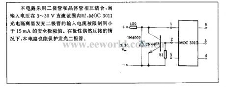
This circuit combines diode with transistor, when the input voltage is in the range of DC 3~30V, the input current of MOC3011 photoelectric isolator LED is limited in the security limit value 15mA. In the case of polarity reverse connection occasionally, this circuit also can protect LED. (View)
View full Circuit Diagram | Comments | Reading(561)
Solid laser range finder reception circuit
Published:2011/4/24 7:29:00 Author:Nicole | Keyword: laser range finder
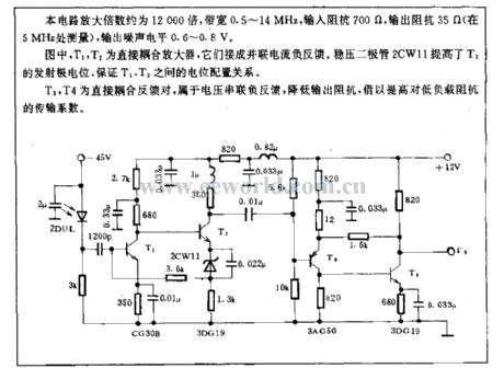
The amplification of this circuit is about 12000 times, the bandwidth is 0.5~14MHz, the input resistance is 700Ω, the output resistance is 35Ω(measured with 5MHz), the output noise level is 0.6~0.8V.
In figure, T1, T2 are direct coupling amplifier, they are connected into parallel current negative feedback. Zener diode 2CW11 improves T2 emitter level, it ensures the level configuration relationship between T1, T2.
T3, T4 is a pair of direct coupled feedback, it belongs to voltage series negative feedback, reducing the output resistance to improve the transmission coefficient of low load resistance. (View)
View full Circuit Diagram | Comments | Reading(2645)
Day and night optical control switch circuit with 10-10LX light intensity
Published:2011/4/22 22:21:00 Author:Nicole | Keyword: optical control switch, 10-10LX light intensity
(View)
View full Circuit Diagram | Comments | Reading(495)
Light intensity control alarm circuit
Published:2011/4/22 23:05:00 Author:Nicole | Keyword: light intensity, alarm
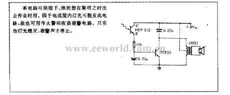
This circuit is used by hunters and fishermen when they want to work at daylight. Because the flashlight or indoor light can trigger this circuit, so it also can be used as fire alarm and burglary alarm circuit. Only the light turns off, the alarm voice will stop. (View)
View full Circuit Diagram | Comments | Reading(584)
Separately excited switching regulated power supply circuit 3
Published:2011/4/25 21:17:00 Author:May | Keyword: Separately excited, switching, regulated power supply
The diagram is separately excited switching regulated power supply circuit which using self-excited multivibrator as pulse generator. In the diagram, VTl is switching tube; VT2, VT3 is pushing tube; VT4 is emitter follower. Separately excited oscillation circuit is self-excited multivibrator consists of VT5, VT6, C2, C3, R3, R4, etc. VT7, VT8 forms emitter-coupled differential amplifier and it uses as error amplifier. Sampling circuit consists of resistor R7, R8 and potentiometer R9 in series. Reference voltage source circuit is composed of diode VD4 and R5. Diode VDl, VD2 is used to prevent the push tube VT2, VT3 emitter breakdown by reverse voltage. VD3 is freewheeling diode; L is energy storage inductor.
Switching regulator's turn-on and cut-off is overturned by multivibrator and controlled by emitter follower VT4.The time of multivibrator’s reversal is determined by error amplifier. That is to say, the reversal time of VT5 from cut off to turned off is determined by the charging current of V8 to C3. If the current of VT is larger, the cut off time of VT5 is longer. (View)
View full Circuit Diagram | Comments | Reading(846)
DUT07 AC distribution box electrical schematic diagram
Published:2011/4/21 21:42:00 Author:muriel | Keyword: distribution box, electrical schematic diagram
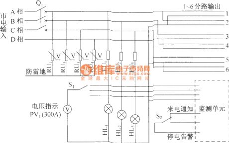
DUT07 HF switch power supply system is based on the DZW75-48/50(50II) type rectifier module with JP50-50II) type AC distribution box. As shown in the figure is the schematic diagram of the P50-AC distribution box. (View)
View full Circuit Diagram | Comments | Reading(1768)
Photoelectric ignition circuit
Published:2011/4/22 20:36:00 Author:Nicole | Keyword: photoelectric ignition circuit
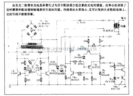
Located at re-greasing distributor cam, the photoelectric sensor is composed of LED and phototransistor. It can eliminate the problems produced by timing drift and re-greasing distributor transfer oil gap. The head of sensor is very small, it can be fixed in majority of re-greasing distributor, its lead wire has no need of shielding. (View)
View full Circuit Diagram | Comments | Reading(930)
Light pipe amplifier circuit
Published:2011/4/24 7:11:00 Author:Nicole | Keyword: light pipe, amplifier circuit
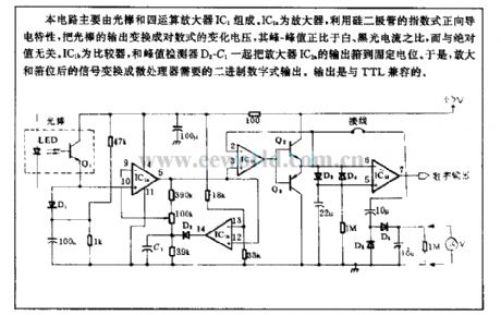
This circuit is composed of light pipe and four operational amplifiers IC1. IC1a is operational amplifier, using silicon diode's exponential positive conductivity to change the light pipe output to logarithmic voltage change, its peak-peak value is in direct proportion to the ratio of white and black light current, it is irrelevant to the absolute value. IC1b is comparator, the output of amplifier IC1a is rose to fixed level by IC1b and peak value detector. So the singal is transferred into the microprocessor needed binary digital output. The output is compatible with TTL. (View)
View full Circuit Diagram | Comments | Reading(707)
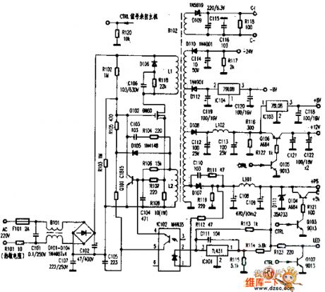
sv-250 power supply circuit diagram
Published:2011/4/26 10:23:00 Author:Nancy | Keyword: power supply
View full Circuit Diagram | Comments | Reading(556)
Steady voltage circuit with adjustable output voltage
Published:2011/4/26 20:35:00 Author:Nicole | Keyword: steady voltage, adjustable output voltage
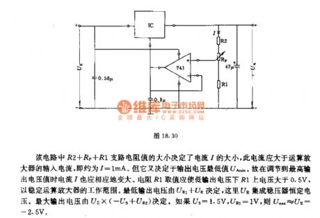
In this circuit, the current I is decided by R2+RP+R1 branch resisitance, the current should be higher than the input currrent of operational amplifier, that is I=1mA. It also depends on the mimimum output voltage UAmin. When the voltage is adjusted to the maximum value, the current I becomes higher too. The resistance R1 should ensure the voltage on R1 higher than 0.5V, to stabilize the work range of operational amplifier. The lowest output voltage is determined by UR1+UR, UR is the integrated regulator constant voltage. The highest output voltage is decided by UE*(-US+UR2). If US=1.5V, UR2=1V, then Umax≈UE=-2.5V. (View)
View full Circuit Diagram | Comments | Reading(460)
Circuit Of On-off Function Remote Voltage Regulator
Published:2011/4/22 3:03:00 Author:Christina | Keyword: Remote, Voltage Regulator, On-off Function
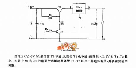
When voltage Us>3V, transistor T2 turns on, and T1 turns on too; but when the Us<0.2V, T1 and T2 turn off. Actually the value of R1 and R2 is related to transistor T1,T2 and operating voltage, you need to adjust the value inexperiment. (View)
View full Circuit Diagram | Comments | Reading(515)
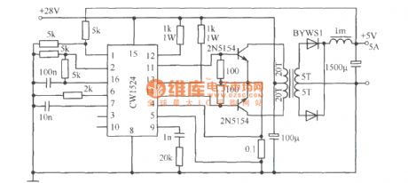
Push pull type switching regulated power supply circuit composed of CW1524
Published:2011/4/26 3:45:00 Author:May | Keyword: Push pull, switching regulated power supply
View full Circuit Diagram | Comments | Reading(575)
Simple nickel-cadmium battery charger
Published:2011/4/25 23:02:00 Author:May | Keyword: Simple, nickel-cadmium, battery charger
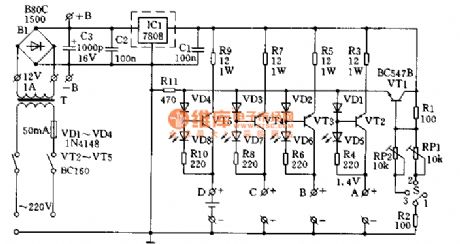
The circuit is shown in diagram 2-2. It consists of three terminal regulator 708 and four loads current source composed of triode VT2~VT5. VT1 and corresponding adjustable resistance RRP1, RP2 and switching tube S is used to control each roads charging current. When S is placed on position 1, charging current of each roads is 90mA; when S placed 2 and 3, it can get 100mA~300mA charging current by adjusting RP1 and RP2. If it adopts current above 200mA to charge, each triode should add radiator. Light emitting diode VD5~VD8 in diagram 2-2 is used as charge indicator. Whole circuit can supply by 220V mains, it also can supply by 12V storage battery. Charge time can count according to the following formula:
Charging time(h)=Nickel-cadmium battery capacity(mAh)/charge current(mA)
In actual use, charging time can proper extended.
(View)
View full Circuit Diagram | Comments | Reading(1273)
Simple constant current charger circuit
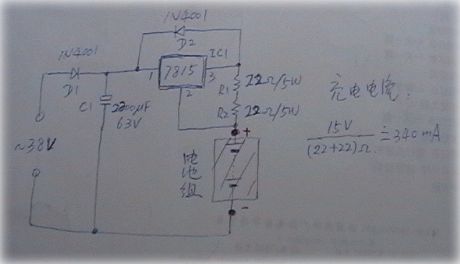
Published:2011/4/26 1:46:00 Author:May | Keyword: constant current charger
View full Circuit Diagram | Comments | Reading(469)
Using KD-28 as voice switching circuit diagram
Published:2011/4/26 3:30:00 Author:Rebekka | Keyword: voice switching
Using KD-28 as voice switching circuit diagram is shown as above. (View)
View full Circuit Diagram | Comments | Reading(661)
Using LA4112 as regulated power supply circuit diagram
Published:2011/4/26 3:19:00 Author:Rebekka | Keyword: regulated power supply
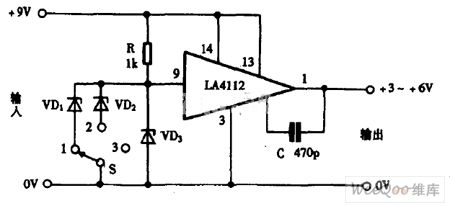
Using LA4112 as regulated power supply circuit diagram is shown as above. (View)
View full Circuit Diagram | Comments | Reading(1030)
| Pages:240/291 At 20221222223224225226227228229230231232233234235236237238239240Under 20 |
Circuit Categories
power supply circuit
Amplifier Circuit
Basic Circuit
LED and Light Circuit
Sensor Circuit
Signal Processing
Electrical Equipment Circuit
Control Circuit
Remote Control Circuit
A/D-D/A Converter Circuit
Audio Circuit
Measuring and Test Circuit
Communication Circuit
Computer-Related Circuit
555 Circuit
Automotive Circuit
Repairing Circuit