
Index 239
Photo coupler data transmission circuit
Published:2011/4/24 8:49:00 Author:Nicole | Keyword: photo coupler, data transmission
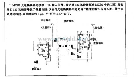
MCD2 photoelectric isolator can receive TTL input singal. Transmitter 322 comparator drives LED of MCD2, receiver 322 comparator is added bias circuit, then it can match with the photodiode output of photoelectric isolator. This circuit is inphase, the delay time is about 2μs. V+ can be 4.5~40V. (View)
View full Circuit Diagram | Comments | Reading(678)
1A transistor integrated circuit driven by photoisolator
Published:2011/4/27 9:42:00 Author:Nicole | Keyword: transistor, opto-electrical isolator drive
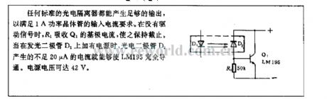
Any standard photoelectric isolator can produce enough output to meet the input current requirement of 1A power transistor. When it is without drive singal, R1 pulls in the Q1's base current, to keep it cut off. To add power supply to LED D1, then LM195 will be absolutely conducted by the insufficient 20μA current which is produced by photodiode D2. The power voltage can reach 42V. (View)
View full Circuit Diagram | Comments | Reading(610)
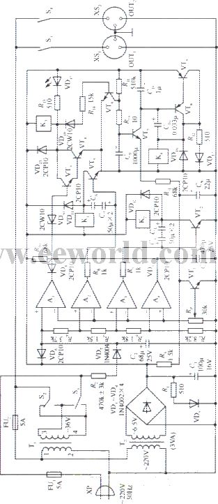
The power supply circuit of high efficient emergency light
Published:2011/4/23 3:14:00 Author:May | Keyword: power supply, high efficient, emergency light

View full Circuit Diagram | Comments | Reading(706)
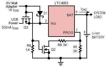
ltc4053 USB charger circuit diagram
Published:2011/4/23 3:13:00 Author:May | Keyword: USB charger
View full Circuit Diagram | Comments | Reading(836)
The principle diagram of 400W switchching power output dc5v/80a
Published:2011/4/11 1:03:00 Author:may | Keyword: switchching power, 400W, output dc5v/80a
View full Circuit Diagram | Comments | Reading(774)
330W AC stabilized voltage supply circuit
Published:2011/4/15 5:34:00 Author:May | Keyword: stabilized voltage supply
View full Circuit Diagram | Comments | Reading(569)
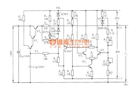
3~120V stabilized voltage supply circuit
Published:2011/4/14 5:58:00 Author:may | Keyword: stabilized voltage supply
View full Circuit Diagram | Comments | Reading(749)
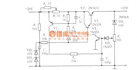
Protective current adjustable 15V stabilied voltage supply
Published:2011/4/15 5:21:00 Author:May | Keyword: Protective current adjustable, 15V, stabilied voltage supply
View full Circuit Diagram | Comments | Reading(556)
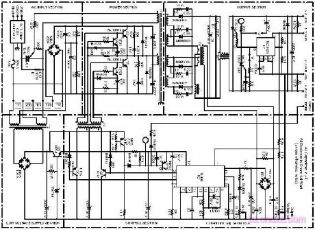
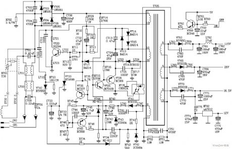
QiSheng DVD-8829 switching power supply circuit diagram
Published:2011/4/11 4:11:00 Author:Rebekka | Keyword: Singular sound , switching power supply

Here is the schematic diagram of theQiShengDVD-8829 switching power supply circuit:
(View)
View full Circuit Diagram | Comments | Reading(4941)
Cursor control circuit
Published:2011/4/27 9:45:00 Author:Nicole | Keyword: cursor control circuit
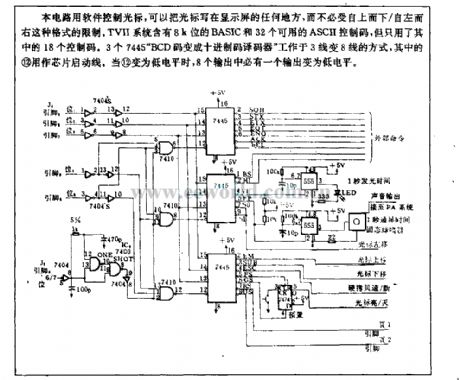
This circuit uses software to control cursor, then the cursor can be writen at any place of display screen, it is not limited by the form of from above to below or from left to right. TVII system contains 8K bits BASIC and 32 usable ASCII control codes, but only 18 codes are used. Three 7445 BCD code changes into BCD decoder work as the way of 3 lines change into 8 lines, the (12) is used as chip start-up line. When the (12) is low level, there must be a output turning into low level. (View)
View full Circuit Diagram | Comments | Reading(641)
TDA two chips switching power supply circuit diagram
Published:2011/4/28 9:31:00 Author:Rebekka | Keyword: two chips , switching power supply
TDA two chips switching power supply circuit diagram is shown as above. (View)
View full Circuit Diagram | Comments | Reading(3989)
Hafeisaima car charging system circuit diagram
Published:2011/4/28 1:38:00 Author:Rebekka | Keyword: Hafeisaima car charging system
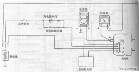
Hafeisaima car charging system circuit diagram is shown as above. (View)
View full Circuit Diagram | Comments | Reading(2117)
Using TDA as positive and negative regulator dual power supply circuit diagram
Published:2011/4/28 1:36:00 Author:Rebekka | Keyword: positive and negative , regulator dual power supply
Using TDA as positive and negative regulator dual power supply circuit diagram is shown as above. (View)
View full Circuit Diagram | Comments | Reading(3563)
Pull-up standard voltage circuit composed of RF2320
Published:2011/4/11 3:02:00 Author:may | Keyword: Pull-up standard voltage
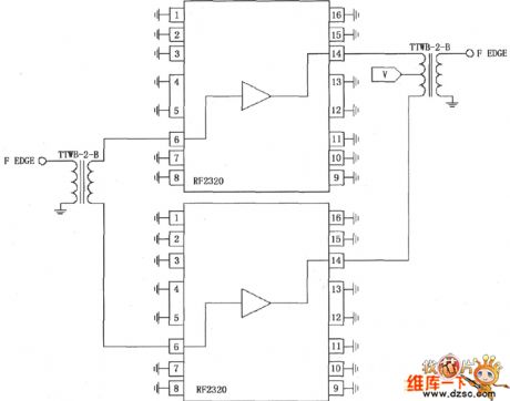
The diagram is pull-up standard voltage circuit composed of RF2320. This circuit uses two transformer TTWB-2-B, one used as input transformer, the other used as output transformer. Using 2 pieces RF2320 to form push-pull circuit. The signal is coupling input through input transformer, get by push-pull enlarge than coupling output by output transformer. Output transfomer centretap offers 7V of power standard voltage.
(View)
View full Circuit Diagram | Comments | Reading(702)
Output boost adjustable power composed Of MAX761 circuit diagram
Published:2011/3/30 5:04:00 Author:may | Keyword: Output boost adjustable, power
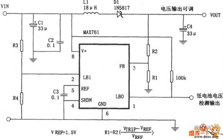
The diagram is output boost adjustable transform power, itconsists of highly active, low power consumption Step Up DC convertor MAX761 and some peripheral cells. The output voltage depends on the specific value of R2 and R1, it can calculate according to the formula V0=(1+R2/R1)×VREF, VREF=1.5V.
(View)
View full Circuit Diagram | Comments | Reading(741)
Multipurpose charging cirucit
Published:2011/4/13 4:10:00 Author:Nicole | Keyword: multipurpose charging
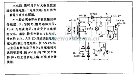
This circuit not only can charge to Ni-Cd battery and dry battery after used by large current, but also can used in general low voltage DC power supply.
The circuit consists of charging part and DC output part. K2 is fast or slow charging selection switch, R2, R3 is limiting resistance, it can change the charging current. Normally, the fast charging is about 4h and slow charging is about 14h. AN, ZD form testing circuit. Before charging,it shouldfix the stay rechargeable battery. When pressed AN, ZD is without light or has low light level, it is normal; When the charging time meets requirement, and press AN, after ZD emitting more than 10s, it means full, it can be used by the electrical equipments. (View)
View full Circuit Diagram | Comments | Reading(588)
Constant current source using integrated regulator circuit
Published:2011/4/26 3:12:00 Author:May | Keyword: Constant current source, integrated regulator circuit
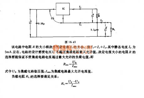
The value of resistor R in this circuit can determine the value of constant current I3. But I3=I1+I2, among them, quiescent current I2 is about 5mA. The design of circuit must make the voltage U not higher than the maximum value of integrated circuit. The selection of resistor R should make sure that the integrated circuit current not higher than maximum load value, namely, Rmin=UR/IMAXIn the formaula, UR is integrated circuit constanst voltage ,IMAX is integrated maximum current value.Load resistor RL must satisfy the following relation:RL=(UE-UR)/IMAX (View)
View full Circuit Diagram | Comments | Reading(838)
Using TDA as positive and negative voltage single-supply circuit diagram
Published:2011/4/27 3:49:00 Author:Rebekka | Keyword: positive and negative voltage , single-supply
Using TDA as positive and negative voltage single-supply circuit diagram is shown as above. (View)
View full Circuit Diagram | Comments | Reading(853)
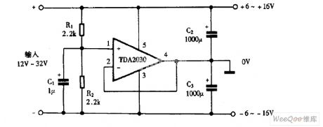
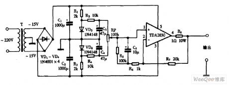
Using TDA2030 as DC power supply circuit diagram
Published:2011/4/27 3:44:00 Author:Rebekka | Keyword: DC power supply circuit
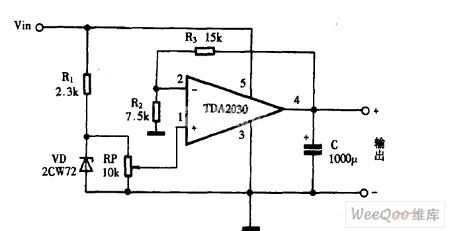
Using TDA2030 as DC power supply circuit diagram is shown as above. (View)
View full Circuit Diagram | Comments | Reading(5629)
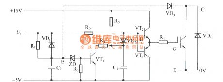
The Driver Circuit of Soft Turn-off Adding Technology
Published:2011/4/21 21:45:00 Author:muriel | Keyword: soft turn-off technological
View full Circuit Diagram | Comments | Reading(783)
| Pages:239/291 At 20221222223224225226227228229230231232233234235236237238239240Under 20 |
Circuit Categories
power supply circuit
Amplifier Circuit
Basic Circuit
LED and Light Circuit
Sensor Circuit
Signal Processing
Electrical Equipment Circuit
Control Circuit
Remote Control Circuit
A/D-D/A Converter Circuit
Audio Circuit
Measuring and Test Circuit
Communication Circuit
Computer-Related Circuit
555 Circuit
Automotive Circuit
Repairing Circuit