
Index 233
5V fixed output linear regulator circuit diagram composed of MIC5158
Published:2011/5/9 22:01:00 Author:Ecco | Keyword: 5V , fixed output , linear regulator
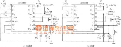
5V fixed output linear regulator circuit diagram composed of MIC5158 is shown as the chart.
(View)
View full Circuit Diagram | Comments | Reading(685)
The integrated regulated power supply circuit diagram with positive and negative voltage output
Published:2011/5/9 22:00:00 Author:Ecco | Keyword: integrated , regulated power supply , positive , negative , voltage, ouput
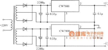
The integrated regulated power supply circuit diagram with positive and negative voltage output composed of CW7800 is shown as the chart.
(View)
View full Circuit Diagram | Comments | Reading(888)
The integrated regulated power supply circuit diagram with fixed negative output voltage
Published:2011/5/9 21:57:00 Author:Ecco | Keyword: integrated , regulated power supply , fixed , negative output , voltage

The integrated regulated power supply circuit diagram with fixed negative output voltage composed of CW7800 is shown as the chart.
(View)
View full Circuit Diagram | Comments | Reading(564)
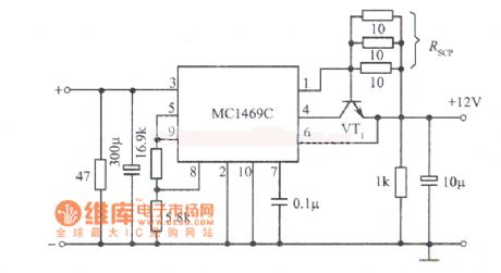
12V regulated power supply circuit diagram with high stability composed of MC1469C integrated voltage regulator
Published:2011/5/9 21:11:00 Author:Ecco | Keyword: 12V , regulated power supply, high stability , integrated voltage regulator
View full Circuit Diagram | Comments | Reading(1272)
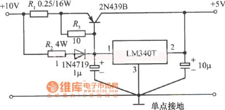
5V, 5A regulated power supply circuit diagram composed of LM340T integrated voltage regulator
Published:2011/5/9 21:08:00 Author:Ecco | Keyword: 5V, 5A, regulated power supply, integrated voltage regulator
View full Circuit Diagram | Comments | Reading(2998)
±15V, 10A power supply circuit diagram composed of MPC1000
Published:2011/5/9 21:07:00 Author:Ecco | Keyword: ±15V, 10A , power supply
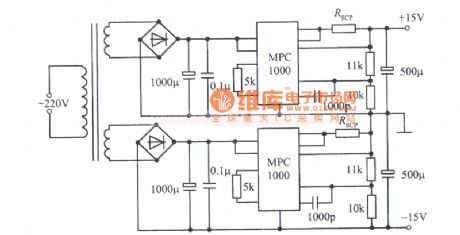
View full Circuit Diagram | Comments | Reading(591)
15V, 5A power supply circuit diagram composed of LM340T-15
Published:2011/5/9 21:00:00 Author:Ecco | Keyword: 15V, 5A , power supply
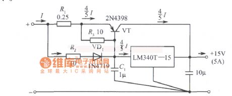
View full Circuit Diagram | Comments | Reading(1386)
12V, 5A power supply circuit diagram composed of LM340K integrated voltage regulator
Published:2011/5/9 20:59:00 Author:Ecco | Keyword: 12V, 5A , power supply, integrated , voltage regulator
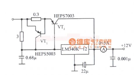
View full Circuit Diagram | Comments | Reading(2957)
28V, 1A power supply circuit diagram composed of SN52105
Published:2011/5/9 20:58:00 Author:Ecco | Keyword: 28V, 1A , power supply
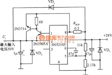
View full Circuit Diagram | Comments | Reading(704)
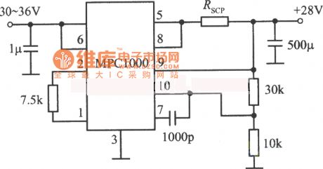
28V, 7A regulated power supply circuit diagram composed of MPC1000
Published:2011/5/9 21:14:00 Author:Ecco | Keyword: 28V, 7A , regulated power supply
View full Circuit Diagram | Comments | Reading(489)
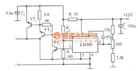
12V, 10A regulated power supply circuit diagram composed of LM305
Published:2011/5/9 21:13:00 Author:Ecco | Keyword: 12V, 10A , regulated power supply
View full Circuit Diagram | Comments | Reading(2341)
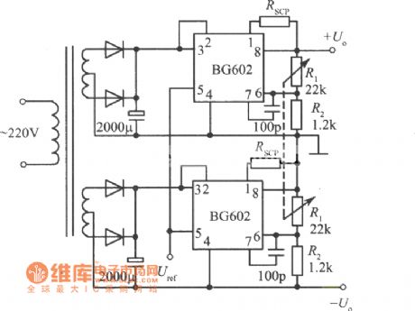
Positive and negative output voltage integrated regulated power supply (BG602) circuit diagram
Published:2011/5/9 21:21:00 Author:Ecco | Keyword: Positive , negative , output voltage , integrated , regulated power supply
View full Circuit Diagram | Comments | Reading(622)
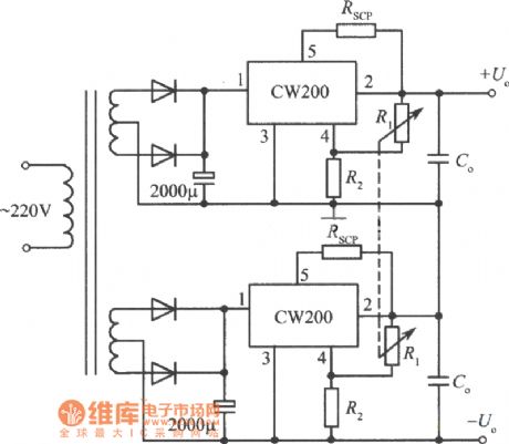
Positive and negative output voltage integrated regulated power supply (CW200) circuit diagram
Published:2011/5/9 21:22:00 Author:Ecco | Keyword: Positive , negative , output , voltage , integrated , regulated power supply
View full Circuit Diagram | Comments | Reading(563)
Tracking integrated regulated power supply (CW200) circuit diagram
Published:2011/5/9 21:24:00 Author:Ecco | Keyword: Tracking , integrated , regulated power supply
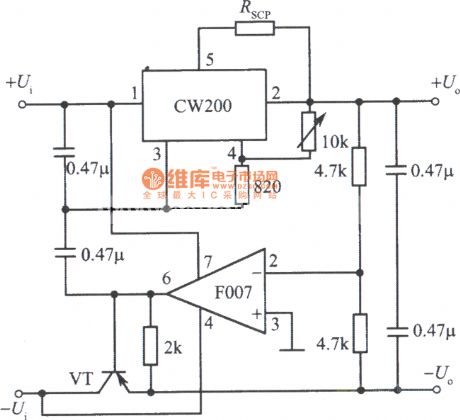
View full Circuit Diagram | Comments | Reading(597)
S13050 5V V terminal voltage regulator integrated circuit diagram
Published:2011/5/9 21:47:00 Author:Ecco | Keyword: 5V , V terminal, voltage regulator , integrated circuit
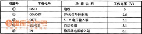
S13050 is 5V V terminal voltage regulator integrated circuit produced by American Microsystems, it is widely used in DVD players, televisions, computer monitors, sound system and various kinds of small household appliances, such as in the regulator circuit. 1. Features of functionS13050 contains +5 V voltage regulator integrated circuit, voltage regulator on / off control circuit, automatic detection circuit, and other ancillary functions circuit. 2. Pin functions and data S13050 integrated circuit uses 5-foot single package, the pin functions and data are listed in Table. S13050 IC pin functions and data
(View)
View full Circuit Diagram | Comments | Reading(640)
Single Display DATAS CH-7423 Power Supply Circuit
Published:2011/5/9 21:36:00 Author:Sharon | Keyword: Single Display, Power Supply
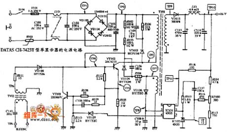
Single Display DATAS CH-7423 Power Supply Circuit is shown below:
(View)
View full Circuit Diagram | Comments | Reading(619)
Constant current battery charger circuit
Published:2011/5/7 12:05:00 Author:John | Keyword: Constant current, battery charger

A three-terminal adjustable output voltage regulator can compose a variety of integrated battery chargers. Figure 1 is a constant current battery charger. The circuit is identical with the constant current source. As resistance for resistor R is 24Ω, the output current Io = 1.25/24 = 52mA. It means that 52mA constant current is used to charge the battery. Changes for resistance value of R can result in different charging current. (View)
View full Circuit Diagram | Comments | Reading(1160)
12V constant voltage battery charger circuit
Published:2011/5/7 12:12:00 Author:John | Keyword: constant voltage, battery charger
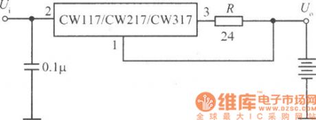
Figure 1 is a 12V constant voltage charger circuit. The circuit is the basically same with a constant power supply. Resistor R1 is 0.2Ω. R1 is used for limiting. It is equivalent to increase the internal resistance of the charger. The charging rate of the initial phase can be reduced. And integrated overcurrent protection on the regulator can be achieved. (View)
View full Circuit Diagram | Comments | Reading(1175)
current limiting battery charger circuit
Published:2011/5/7 12:28:00 Author:John | Keyword: battery charger, current limited protection
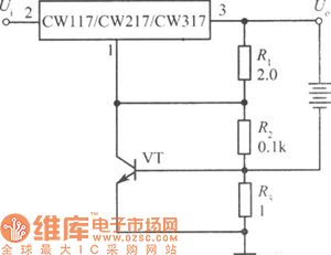
Figure 1 is a current limiting battery charger. VT transistor and resistor R3 form the limiting network. According to the figure, resistor R3 is a base-emitter power resistor of the transistor VT. It is connected in series with rechargeable batteries. Charging current flows through resistor R3. When the charge current is too large, the voltage drop on R3 exceeds 0.6V, the transistor VT can be conducted. As resistor R2 is in parallel with VT, the conduction of VT leads to the reduction of the equivalent parallel resistance. The output voltage Uo reduces and the output current decreases. So the purpose of limiting charging current is achieved. When taking R3 = lΩ), the maximum charge current is Iom = 0.6 / 1 = 0.6A. Select the R3 of a smaller resitance, so charging current can be larger. But the charging current can not exceed the maximum output current value of the integrated voltage regulator. (View)
View full Circuit Diagram | Comments | Reading(1273)
The Intergrated Circuit of HICIO15 Switch Control
Published:2011/5/9 8:33:00 Author:Borg | Keyword: Intergrated Circuit, Switch Control, HICIO15
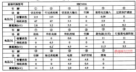
Table 1-1 the pinning functions and data of HIC1015 intergrated circuit (View)
View full Circuit Diagram | Comments | Reading(563)
| Pages:233/291 At 20221222223224225226227228229230231232233234235236237238239240Under 20 |
Circuit Categories
power supply circuit
Amplifier Circuit
Basic Circuit
LED and Light Circuit
Sensor Circuit
Signal Processing
Electrical Equipment Circuit
Control Circuit
Remote Control Circuit
A/D-D/A Converter Circuit
Audio Circuit
Measuring and Test Circuit
Communication Circuit
Computer-Related Circuit
555 Circuit
Automotive Circuit
Repairing Circuit