
Index 229
HM9113A-The Intergrated Circuit of Microcomputer Dialing
Published:2011/5/11 2:09:00 Author:Borg | Keyword: Intergrated Circuit, Microcomputer Dialing

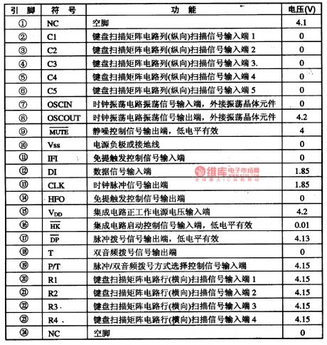
Pin functions and dataof HM9113 are listed in Table 1-1.
Table 1-1 pin functions and data of HM9114A (View)
View full Circuit Diagram | Comments | Reading(585)
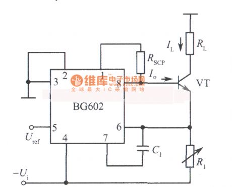
Adjustable constant current source circuit diagram composed of BG602
Published:2011/5/11 1:32:00 Author:Ecco | Keyword: Adjustable , constant current source
View full Circuit Diagram | Comments | Reading(1022)
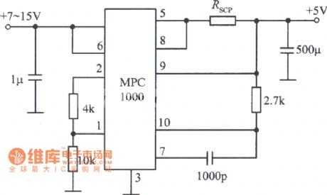
5V, 3A regulated power supply circuit diagram composed of MPC1000 integrated regulator
Published:2011/5/11 1:39:00 Author:Ecco | Keyword: 5V, 3A , regulated power supply , integrated regulator
View full Circuit Diagram | Comments | Reading(1026)
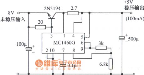
5V regulated power supply circuit diagram composed of MC1460G integrated regulator
Published:2011/5/11 1:40:00 Author:Ecco | Keyword: 5V , regulated power supply, integrated regulator
View full Circuit Diagram | Comments | Reading(593)
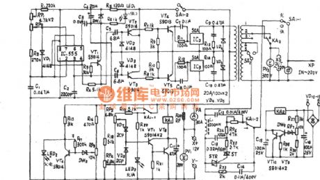
JZ Series-II of 150W multi-function emergency power supply circuit diagram
Published:2011/5/11 1:46:00 Author:Ecco | Keyword: JZ Series-II , 150W , multi-function , emergency power supply
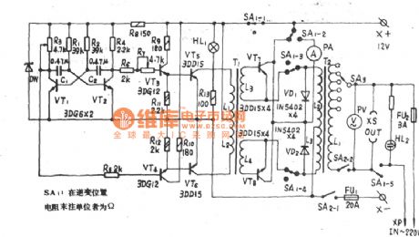
JZ Series-II of 150W multi-function emergency power supply circuit diagram is shown as the chart.
(View)
View full Circuit Diagram | Comments | Reading(804)
JDE-200 multi-function emergency power supply circuit diagram
Published:2011/5/11 1:47:00 Author:Ecco | Keyword: multi-function, emergency power supply
JDE-200 multi-function emergency power supply circuit diagram is shown as the chart.
(View)
View full Circuit Diagram | Comments | Reading(1367)
AC Voltage Regulator One
Published:2011/5/7 5:16:00 Author:Joyce | Keyword: AC Voltage Regulator, One
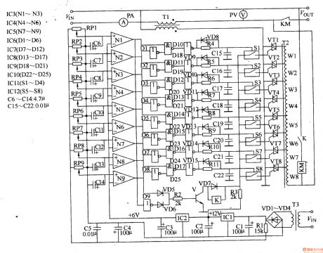
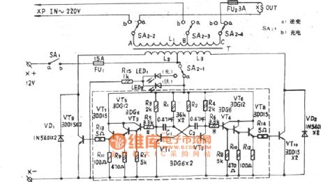
Here is an introduction of an automatic non-contactor compensating AC stabilizer.It changes second offset voltage by controlling primary voltage of the transformer,thus solving the power outages problems in regulating the circuit.The input voltage of AC stabilizer is 167 - 264V,and output voltage is 220 (1土5%) V.Operating principleThe AC stabilizer circuit consists of a power supply voltage-stabilising circuit,an input comparison circuit, a coding control circuit,a compensating output circuit and overvoltage/undervoltage protection circuit , as shown in figure 5-40.
The power supply voltage-stablising circuit consists of power transformer T3, commutation diode VDl- VD4, filter capacitor Cl - C3 and three-terminal integrated regulator IC1,IC2. The Input comparison circuit consists of resistors Rl,potentiometerRPl - RP9, capacitorsC6 - Cl4 and N1- Ng within integrated circuit lC3-1C5 of operational amplifiers .The Coding control circuit consists of NOT gate integrated circuitIC6 -1C8 , NAND gate integrated circuit IC9, IC10,glaze diode VD8 - VDl5, resistorsR4 - Rll and capacitors C15 -C22 .The compensating output circuit consists of integrated circuit ICl (Sl - S4), ( IC17S5 - S8) of electronic switch ,thyristor VTl-VT8, main compensating transformer Tl, assistant compensating transformer T2, AC contactors KM and voltmeter PV, ammeter PA .The over-voltage/under-voltage protection circuit consists ofNOT gate D9 witin IC7 , diodes VD5 - VD7, resistors R2, R3, transistor V and relay K.The assistant compensating transformer is a bodying transformer, which would provide different primary voltages to fulfill different second compensating voltages of T1 . (View)
View full Circuit Diagram | Comments | Reading(4897)
TJ-200VA emergency power supply circuit diagram
Published:2011/5/10 21:50:00 Author:Ecco | Keyword: emergency , power supply
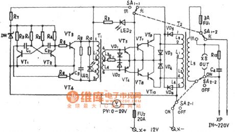
TJ-200VA emergency power supply circuit diagramis shown as the chart.
(View)
View full Circuit Diagram | Comments | Reading(543)
ZD12 150VA emergency power supply circuit diagram
Published:2011/5/10 21:49:00 Author:Ecco | Keyword: 150VA , emergency , power supply
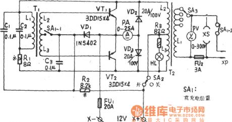
ZD12 150VA emergency power supply circuit diagramis shown as the chart.
(View)
View full Circuit Diagram | Comments | Reading(528)
SD-120A dual-function emergency power supply circuit diagram
Published:2011/5/10 21:13:00 Author:Ecco | Keyword: dual-function , emergency power supply
SD-120A dual-function emergency power supply circuit diagram is shown as the chart.
(View)
View full Circuit Diagram | Comments | Reading(709)
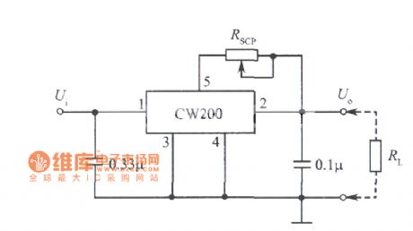
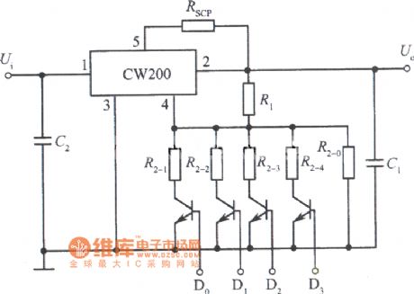
Adjustable constant current source circuit diagram composed of CW200
Published:2011/5/10 20:32:00 Author:Ecco | Keyword: Adjustable , constant current source
View full Circuit Diagram | Comments | Reading(1135)
HT9215D-The Intergrated Circuit of PC Dialing
Published:2011/5/10 8:46:00 Author:Borg | Keyword: Intergrated Circuit
The HT9215D intergrated circuit of PC dialing is widely used in all kinds of phones.
1. Function Features
HT9212D intergrated circuit contains sub circuits of pulse/tone compliant dialing and key switch signal encoding/decoding.
2.pin functions and relevent data
Pin functions and relevent data of the HT9215D intergrated circuit are listed in Table 1-1.
Table 1-1 Pin functions and relevent data of the HT9215D intergrated circuit (View)
View full Circuit Diagram | Comments | Reading(908)
Circuit of DC Motor Driver with Resistor Providing A Path of Returning Signal Current
Published:2011/5/10 2:23:00 Author:Felicity | Keyword: DC Motor Driver, Resistor
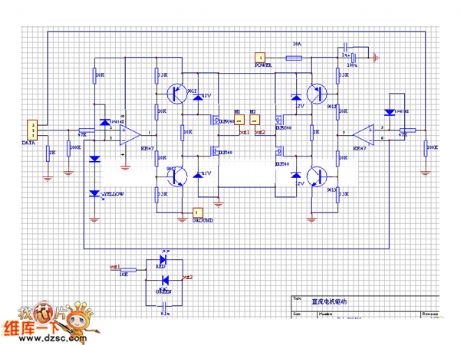
The picture above shows the circuit of DC motor driver with resistor provides a path of returning signal current. (View)
View full Circuit Diagram | Comments | Reading(597)
Logic control integrated regulated power supply circuit diagram composed of CW200
Published:2011/5/10 20:47:00 Author:Ecco | Keyword: Logic control , integrated , regulated power supply
View full Circuit Diagram | Comments | Reading(560)
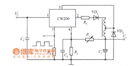
Separately excited switching integrated regulated power supply circuit diagram composed of CW200
Published:2011/5/10 20:30:00 Author:Ecco | Keyword: Separately excited, switching , integrated , regulated power supply
View full Circuit Diagram | Comments | Reading(506)
LM7806 formed full-automatic Nickel cadmium battery charging circuit diagram
Published:2011/5/9 0:16:00 Author:Crystal Liu | Keyword: full-automatic Nickel cadmium battery charging circuit

The charging circuit uses fold point voltage method to charge the nickel cadmium battery . When the battery is plentiful, charge current will be reduced to 8mA automaticly, meanwhile light diode indicates charging end,so it can not produce the phenomenon of overcharge and Owe filling,thus prolong life of the Nickel cadmium battery. (View)
View full Circuit Diagram | Comments | Reading(2512)
Constant current & voltage lithium battery charger circuit
Published:2011/5/9 6:25:00 Author:Christina | Keyword: Constant current & voltage, lithium battery charger
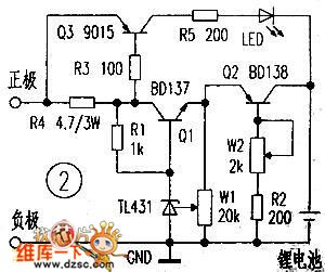
This device is designed as one kind of constant current & voltage lithium battery charger circuit, the precision adjustable voltage regulator is composed of the Q1, R1, W1, TL431. The adjustable constant current circuit is composed of the Q2、W2、R2. The charging indicator circuit is composed of the Q3、R3、R4、R5 and LED. As the charged battery's voltage increases gradually, the charge current will be reduced gradually, when the battery is full, R4's pressure-drop will be decreased, and the Q3 cuts off, the LED turns off to ensure the battery is sufficient, please continue to charge the battery for 1-2 hours after the indicator light turns off, you need to install the heatsink on Q2 and Q3.
(View)
View full Circuit Diagram | Comments | Reading(1672)
Light control integrated regulated power supply circuit composed of CW7800
Published:2011/5/10 0:49:00 Author:Rebekka | Keyword: Light control integrated regulated power supply
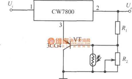
Here is the diagram of light control integrated regulated power supply circuit composed of CW7800. (View)
View full Circuit Diagram | Comments | Reading(588)
0~20V adjustable regulated power supply circuit composed of μA723
Published:2011/5/10 0:46:00 Author:Rebekka | Keyword: 0~20V adjustable regulated power supply
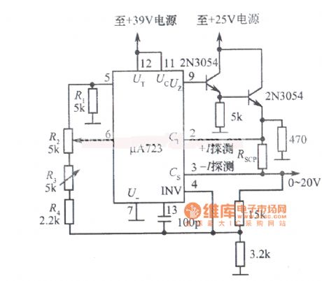
View full Circuit Diagram | Comments | Reading(1563)
1.25 to 37V 1.5A adjustable regulated power supply circuit composed of LM117
Published:2011/5/9 22:54:00 Author:Rebekka | Keyword: 1.25 to 37V 1.5A adjustable regulated power supply
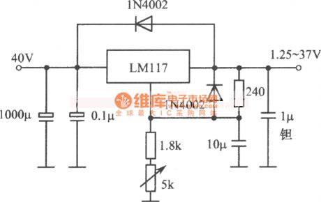
View full Circuit Diagram | Comments | Reading(676)
| Pages:229/291 At 20221222223224225226227228229230231232233234235236237238239240Under 20 |
Circuit Categories
power supply circuit
Amplifier Circuit
Basic Circuit
LED and Light Circuit
Sensor Circuit
Signal Processing
Electrical Equipment Circuit
Control Circuit
Remote Control Circuit
A/D-D/A Converter Circuit
Audio Circuit
Measuring and Test Circuit
Communication Circuit
Computer-Related Circuit
555 Circuit
Automotive Circuit
Repairing Circuit