
Index 223
Power-supply of adjustable DC steady voltage
Published:2011/5/23 7:55:00 Author:Ariel Wang | Keyword: adjustable, DC , steady voltage
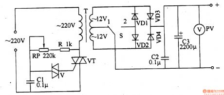
Adjust the resistance of RP.It can change the conduction angle of VT. Then it can change the power-supply of DC steady voltage of input voltage and output voltage.
The 220V AC voltage is adjusted through electronic voltage regulation switch,dropped down through T,commutated through VD1-VD4 and filtered through C2,C3. Then it generates DC voltage needed.
Put S to position 1 ,VD3 and VD4 make up a full wave commutated circuit. At this time the power-supply of DC steady voltage is low voltage output.Put S to position 2 ,VD1-VD4 make up a three-phase-bridge rectifier circuit. At this time the power-supply of DC steady voltage is high voltage output.
(View)
View full Circuit Diagram | Comments | Reading(668)
KBC-Ⅱ programmable power supply circuit diagram
Published:2011/5/12 22:29:00 Author:Rebekka | Keyword: programmable power supply

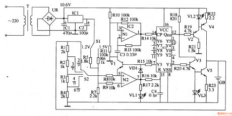
KBC-Ⅱ programmable power supply circuit is composed of the D/A converter, voltage reference, voltage comparators, operational amplifiers Al ~ A3, the output voltage adjustable regulator, CPU, monitor and keyboard. The order and the sizeof the output voltage is set by the keyboard and achieved by computer control. The principle circuit diagram of the programmable power supply is shown as above. (View)
View full Circuit Diagram | Comments | Reading(2595)
Toshiba CV60 elevator control power supply circuit
Published:2011/5/19 8:52:00 Author:TaoXi | Keyword: Toshiba, elevator, control power supply
Toshiba CV60 elevator control power supply circuit (View)
View full Circuit Diagram | Comments | Reading(601)
AN6650-the integrated motor speed-stable circuit
Published:2011/5/19 6:50:00 Author:Borg | Keyword: integrated, speed-stable
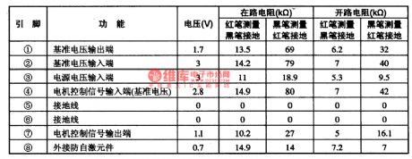
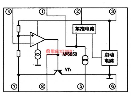
AN6650 is an integrated motor speed-stable circuit produced by Panasonic, which is use to control the speed of the reproducing motor.1.The internal circuit and pin functions of AN6650The internal circuit of AN650 is as shown in Figure 1, and it contains sub-circuits, such as reference voltage circuit, comparing circuit and starting circuit, etc. The IC is in 8-lead dual in-line package, and its pin functions and data are listed in Table 1.
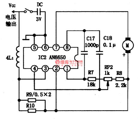
2.the typical application circuit of AN66635The typical application circuit of AN66635 is as shown in Figure 1.
3.working process (View)
View full Circuit Diagram | Comments | Reading(6819)
AN6612/S-the integrated circuit of DC motor speed-stable control
Published:2011/5/19 7:16:00 Author:Borg | Keyword: integrated circuit, DC motor, speed-stable
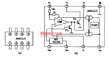
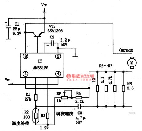
1.the internal circuit and pin functions of AN6612/SThe internal circuit of AN6612/S is shown in Figure 1(b), and the IC contains sub-circuits of voltage comparator, reference voltage forming, combination regulator, current source and starter, etc.
Figure 1 the internal circuit and outline pin arrangement of AN6612/S
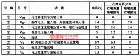
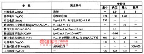
AN6612/S is in flat 8-lead dual in-line plastic package, whose outline pin arrangement are as shown in Figure 1(a). Its pin functions and data are listed in Table 1.2. The main electric parameters of AN6612/S
(View)
View full Circuit Diagram | Comments | Reading(2073)
The e-glass elevating and control door lock wiring circuit of DPCA-VOLCANE DC7140
Published:2011/5/19 10:11:00 Author:Borg | Keyword: door lock, wiring circuit, DPCA-VOLCANE
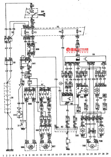
See as the figure: the e-glass elevating and control door lock wiring circuit of DPCA-VOLCANE DC714035-battery; 50-power supply box; 52-inscribing fuse box; 55-controller of the centralized control lock; 58-e-control components; 62-ground connection box; 300-igniting switch; 310-left-front lamp switch; 311-right-front lamp switch; 590,591,592-glass elevation motor switch; 696,697-glass elevation motor; 703,704,705,706 and 708-door lock motor; 809-glass elevating relay; 841-glass elevating motor relay (View)
View full Circuit Diagram | Comments | Reading(874)
Randomness electronic small toys circuit
Published:2011/5/19 18:56:00 Author:Christina | Keyword: Randomness, electronic small toys
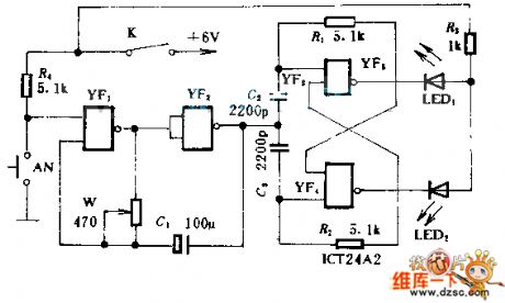
This toys circuit can be played by two or more people. Before you press AN, open the circuit, LED1 and LED2 will shine alternately; if you press AN2, there is only one LED alternately shines. If LED1 shining means one person gets 1 point, LED2 shining means one person loses 1 point, so we can ensure who is the winner according to the number of points.
(View)
View full Circuit Diagram | Comments | Reading(764)
The stereo system circuit of DPCA-VOLCANE DC714OZX
Published:2011/5/19 11:16:00 Author:Borg | Keyword: stereo system, DPCA-VOLCANE
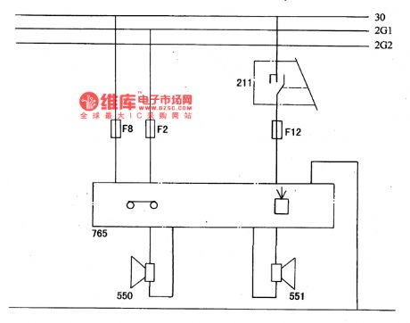
The left and right loudspeakers are controlled by the left combination switch, when the igniting switch is at A gear and M gear, then the radio can be used(see as Figure a and b).
Figure a. The principle stereo circuit of DPCA-VOLCANE DC714OZX211-left combination switch; 550,551-left and right loudspeakers; Fl-FI3-fuse box
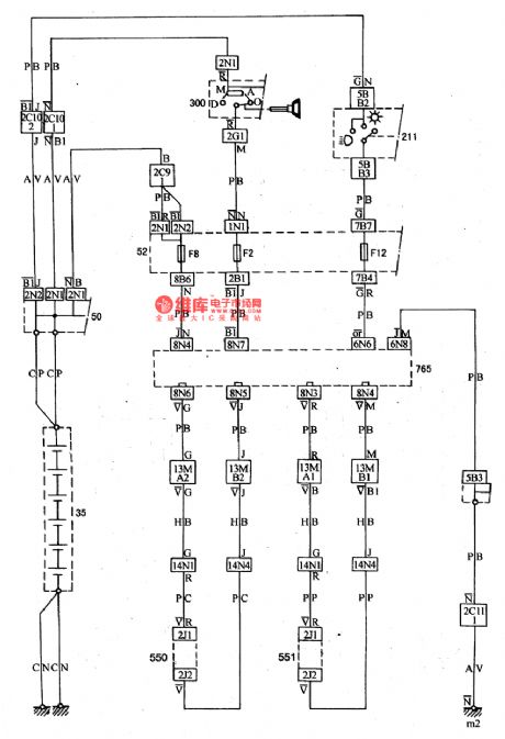
Figure b. The stereo system wiring circuit of DPCA-VOLCANE DC714OZX35-battery; 50-power supply box; 52-inscribing fuse box; 62-ground connection box; 211-left combination switch; 300-igniting switch; 550,551-left and right loudspeakers; 765-radio (View)
View full Circuit Diagram | Comments | Reading(601)
The room light, cigarette lighter and clock principle circuits of DPCA-VOLCANE DC714OZX
Published:2011/5/19 11:55:00 Author:Borg | Keyword: room light, cigarette lighter, principle circuit, DPCA-VOLCANE
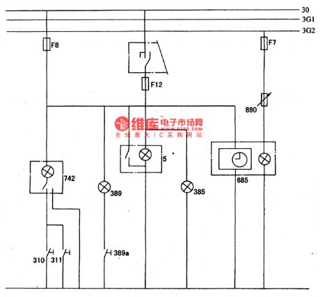
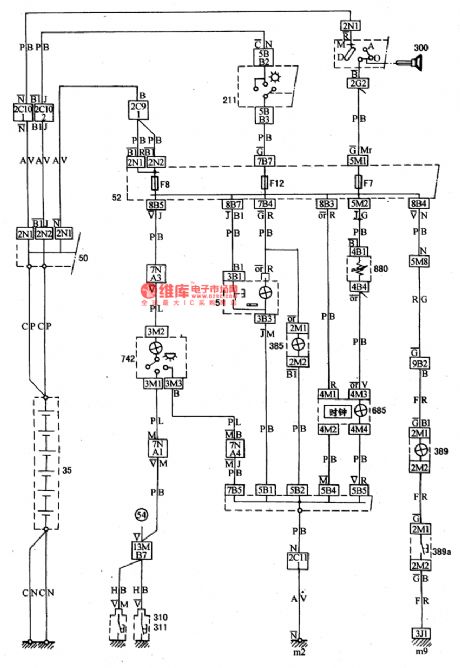
The fuse of F8 links with the battery fire wire, and it controls the room light(742), trunk(389), cigarette lighter and clock(685). The room light can be shut down by hand switch, or controlled by switches of 310 and 311(see as Figure a and b).
Figure a. The room light, cigarette lighter and clock principle circuits of DPCA-VOLCANE DC714OZX5-cigarette lighter; 310,311-the left and right front door switches; 385-ashtray light; 389-trunk light; 389a-trunk light switch; 685-digital clock; 742-head ceiling light; 880-instrument lamp.
(View)
View full Circuit Diagram | Comments | Reading(652)
Multifunction Charger Seven
Published:2011/5/18 10:39:00 Author:Michel | Keyword: Multifunction Charger Seven
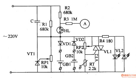
The multifunction charger introduced in the example has the functions of constant current pulse charging,voltage limiting protection,constant and excess temperature protection.It can charge one nickel-spread and nickel-hydrogen battery.
Circuit's Work Principle
This Multifunction charger consists of step-down capacitor,C,thyristor,VT1 and VT2,resistor,R1-R4,diode,VD1,VD2,potentiometer,RP1 and RP2,heat-variable resistor,RT and LED VD1 and VD2 and it's showed as the picture 5-69.The alternating voltage(220V) charges batteries GB1 and GB2 via VD1 and VD2 when it reduces voltage through C. (View)
View full Circuit Diagram | Comments | Reading(969)
Multifunction Charger Six
Published:2011/5/18 10:32:00 Author:Michel | Keyword: Multifunction Charger Six
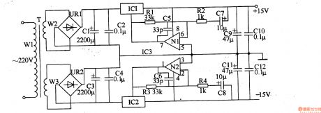
The Multifunction charger introduced in the example can charge nickel-hydrogen batteries and alkaline cells with simple circuit and material.It can charge four pieces of battries at the most one time and stop charging automatically when batteries are fully charged.Circuit's Work PrincipleThis multifunction charger consists of mains transformer,T, rectifier bridge,UR, three-terminal adjustable IC regulator,IC,transistor,V1-V4,LED,VL1-VL4,resistor,R1-R9 and potentiometer,RP and it's showed as the picture 5-68.The alternating voltage(220v) changes to 6v volts d.c.when it passes T and UR.The voltage is added to VLl-VL4's anode as charging voltage and used as charging reference voltage when it passes IC. (View)
View full Circuit Diagram | Comments | Reading(574)
Multifunction Charger Eight
Published:2011/5/18 10:43:00 Author:Michel | Keyword: Multifunction Charger Eight
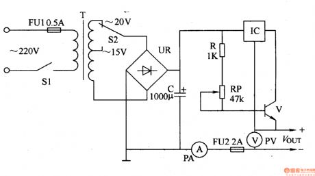
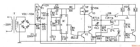
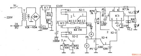
Simple circuit and convenience are features of the multifunction charger introduced in the example.It can charge 1.2-12V nickel-spread nickel-hydrogen and lead-acid batteries and also be used as working power supply of household appliances such as walkman.
Circuit's Work Principle
This multifunction charger consists of voltage change circuit and voltage regulation circuit and it is showed as the picture 5-70.The voltage change circuit is composed of mains switch,S1,voltage-selected switch,S2,fuse plug,FU1,mains transformer,T and rectifier bridge UR and filter capacitor,C.
(View)
View full Circuit Diagram | Comments | Reading(619)
Multifunction Charger Five
Published:2011/5/18 10:28:00 Author:Michel | Keyword: Multifunction Charger Five
Besides nickel-pick batteries,nickel-hydrogen cells and lithium-ion batteries,the Multifunction charger introduced in the example can also chagres plain alkaline cells and it chagres two to six pieces of batteries at a time.
Ciruit's Work Principle
This multifunction charger consists of voltage regulator circuit,charging circuit and discharge circuit,battery selection or voltage detection circuit and sequential control circuit and is showed as the picture 5-67,The voltage regulator circuit is composed of mains transformer,T,rectifier bridge UR circuit,filter capacitor,C1 and C2 and three-terminal voltage regulation IC,IC1. (View)
View full Circuit Diagram | Comments | Reading(1365)
DYMK-2- the integrated circuit of switching power supply thick films
Published:2011/5/16 20:40:00 Author:Borg | Keyword: integrated circuit, power supply, thick films
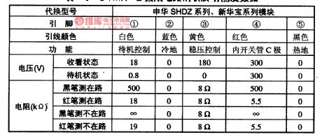
DYMK-2 is an integrated circuit of switching power supply thick films, which is suited in modifying and replacing series switching power supply of all kinds of color TV sets.1.pin functions and dataDYMK-2 is in 5-pin single in-line package, whose pin functions and data are listed in 1-1.
2.InstructionsIn Table 1-1, ① and ④ are the hot-ground detection, while ③ is the cold-ground detection.Color TV screens smaller than 54cm are installed with 21-Ⅱ module, while screens of 60cm are installed with 25-Ⅱandscreens larger than 74cm are installed with 29-Ⅱ. (View)
View full Circuit Diagram | Comments | Reading(646)
Multifunction Charger Three
Published:2011/5/18 10:15:00 Author:Michel | Keyword: Multifunction Charger Three
The Multifunction charger introduced in the example can charge nickel-spread and nickel-hydroge batteries.Before charging,the charger discharges batteries and switches into constant current charging.During charging,there is a heavy load current and batteries cut off charge circuit wnen they are fully charged automatically to avoid excessive charging.Ciruit's Work PrincipleThis multifunction charger is composed of power supply circuit, impulsator,charging circuit,discharging circuit and control circuit.Power supply circuit consists of mains transformer,T,commutation diode,VDl-VD4,filter capacitors,C1and C2,line regulation tube,V1,voltage regulator diodes,VS1 and VS2,resistors,R1,R2 and R5 and LED,VL1 and it is showed as the picture 5-65. (View)
View full Circuit Diagram | Comments | Reading(767)
Common Electrical Motor Controlled Circuit (1)
Published:2011/5/13 5:42:00 Author:Sue | Keyword: Common, Electrical Motor, Controlled
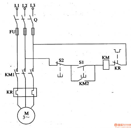
Working Principle: As seen in the figure 4-111, the circuit consists of switch Q, fuse FU, ac contactor KM, start button S1, stop button S2 and thermal relay KR. When we start the circuit, we should connect the switch Q, and push the start button S1. Then KM is connected, which make KM1 and KM2 connected, and the motor M begins to work. When S1 is disconnected, KM is still connected because of KM2's effect. When we stop the circuit, we should push the stop button S2, and KM is disconnected, which make KM1 and KM2 disconnected, and M stops working. (View)
View full Circuit Diagram | Comments | Reading(4507)
Common Electrical Motor Controlled Circuit (2)
Published:2011/5/13 5:41:00 Author:Sue | Keyword: Common, Electrical Motor, Controlled
Working Principle:
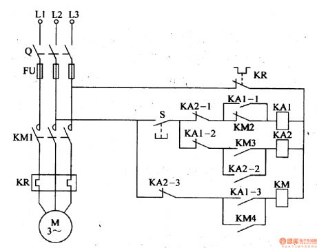
As seen in the figure 4-112, the button controlled motor circuit consists of knife switch Q, fuse FU, ac contactor KM, thermal relay KR, intermediate relay KA1,KA2 and control button S.
When we start the circuit, we should connect the knife switch Q, and push S to connect KA1, which will connect KA1-1 and KA13. The normally closed interlock KA1-2 is disconnected, which makes normally opened main interlock KM1 and assist interlock KM3,KM4 connected, and M begins to work. When S is released, KA is disconnected, and KM is still connected under the action of KM4.
When we stop the circuit, push S, and KA2 is connected, normally opened interlock KA2-2 is connected, while normally closed interlock KA2-1 and KA2-3 are disconnected, which makes KM released, then M stops working. (View)
View full Circuit Diagram | Comments | Reading(4070)
multi-bit counter circuit used to performance
Published:2011/5/16 18:44:00 Author:Christina | Keyword: multi-bit counter, performance
This counter circuit can be used in the demonstration teaching and the science and technology exhibition applications, every bit of this counter is composed of the decimal counter RS7490, the RS7447 decoder and the 7 segment digital tube. If you want to add two stages more, the monitor must gets to the number of 9999 to start a new count cycle. The diode 1N914 which connects with the battery can be used to prevent the wrong polarity of power supply, and you need to reduce the power supply voltage to 5V to meet the integrated circuit's need.
(View)
View full Circuit Diagram | Comments | Reading(552)
Multifunction Charger Two
Published:2011/5/17 3:37:00 Author:Michel | Keyword: Multifunction Charger, Two
Multifuntction charger introduced in the example charges lithium-ion rechargeable battery,nickel-hydrogen battery,nickel-pick battery with constant current.It can charge two pieces of batteries at a time and become supplementary charging when the batteries are fully charged.Circuit's Work PrincipleThis charger is composed of power supply circuit and charging circuit and it's showed as the picture 5-64.Power supply circuit is composed of mains switch,S1,fuse plug,mains transformer,T,commutation diode,VDl-VD4,filter capacitor,Cl and C2,three-terminal IC,IC1,resistor,R1,and regulation resistance,RP. (View)
View full Circuit Diagram | Comments | Reading(602)
10H2 to 2MH2 frequency counter circuit
Published:2011/5/16 19:18:00 Author:Christina | Keyword: frequency counter, 10H2, 2MH2
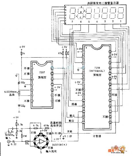
The 7208 seven-stage decimal counter can be used as the frequency counter, it has the latch and multiplexing functions, and it has the direct digital driving circuit and the display driving circuit. 7207IC 6.5536MHZ crystal oscillator's output frequency is divided by 2K to create the 1600HZ square wave for the multiple conversions of the calculator and the monitor. After the frequency demultiplication, this circuit produces the 0.1S and 0.01S calculation measurement selective passing signal and the reset command pulse, modification command pulse. RCA company's 3130 operational amplifier can be used to optimize the input signal.
(View)
View full Circuit Diagram | Comments | Reading(3151)
| Pages:223/291 At 20221222223224225226227228229230231232233234235236237238239240Under 20 |
Circuit Categories
power supply circuit
Amplifier Circuit
Basic Circuit
LED and Light Circuit
Sensor Circuit
Signal Processing
Electrical Equipment Circuit
Control Circuit
Remote Control Circuit
A/D-D/A Converter Circuit
Audio Circuit
Measuring and Test Circuit
Communication Circuit
Computer-Related Circuit
555 Circuit
Automotive Circuit
Repairing Circuit