
Index 224
Multifunction Charger One
Published:2011/5/17 3:34:00 Author:Michel | Keyword: Multifunction Charger, One
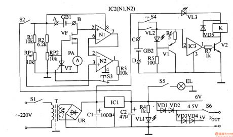
The Multifunctions Charger introduced in the example can charge in constant-current way,charge in regulating current way and the maximum current is 500nA.It can carry out standard and fast charge and stop charging automatically when the battery is fully charged.This charger can charge two pieces of aa(aaa)nickel-spread battery,nickel-hydrogen batteries,alkaline cells at a time.It also can be used as the constant-voltage power supply of miniature radios and videocorders.Circuit's Work PrincipleThis multi-functions charger is composed of power supply circuit,lamp circuit and discharge circuit and it's showed as the picture 5-63. (View)
View full Circuit Diagram | Comments | Reading(580)
RC reset circuit increases the discharge loop
Published:2011/5/16 7:39:00 Author:Christina | Keyword: discharge loop, RC reset circuit
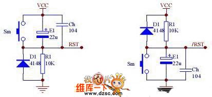
You can solve the system instability which is caused by the power glitch by using the comparison circuit, and the power slow dropping can be reliably reset. Figure 4 is the example: when VCCx(R1/(R1+R2))=0.7V, Q1 closes to reset the system Q1. The amplification of Q1 also improves the load characteristics of the circuit, but the transition threshold voltage Vt is affected by the Vcc, this is the most prominentest weak point of this circuit, so you can use the zener diode to make the Vt will not affected by the Vcc. Figure 5: when Vcc is lower than Vt(Vz+0.7V), the circuit reset the system.
Figure: RC reset circuit increases the discharge loop (View)
View full Circuit Diagram | Comments | Reading(3677)
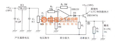
Lithium Dry Battery Charger Five
Published:2011/5/16 23:02:00 Author:Michel | Keyword: Lithium Dry battery Charger, Five
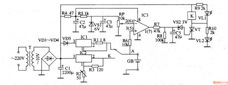
The lithium battery charger introuduced in the example can charge 6V-plated ion battery in constant-current way and change into constant-voltage chagre mode when the battery reaches 4·1V.
Work Principle of the Circuit
This lithium battery charger circuit is composed of power supply constant voltage circuit,oscillator,voltage detection control circuit,constant-current charge circuit and constant-voltage charge circuit and it's showed as the picture 5-77.
The power supply constant-voltage circuit is composed of power supply transformer,T,commutation diode,VDl-VD4,filter capacitor,CI and C2 and three-terminal voltage control IC1. (View)
View full Circuit Diagram | Comments | Reading(2503)
Bipolar Voltage-Stabilizing Circuit with Three Terminal Regulators
Published:2011/5/17 8:02:00 Author:Joyce | Keyword: Bipolar , Voltage-Stabilizing , with Three Terminal Regulators
View full Circuit Diagram | Comments | Reading(666)
Regulated Power Supply Circuit with Operational Amplifier
Published:2011/5/17 7:53:00 Author:Joyce | Keyword: Regulated , Power Supply, with Operational Amplifier
View full Circuit Diagram | Comments | Reading(754)
Transistor Voltage-stabilizing Circuit
Published:2011/5/17 8:00:00 Author:Joyce | Keyword: Transistor , Voltage-stabilizing

View full Circuit Diagram | Comments | Reading(714)
Voltage-stabilizing and Constant-current Circuit with Operational Amplifier
Published:2011/5/17 7:56:00 Author:Joyce | Keyword: Voltage-stabilizing and Constant-current, with Operational Amplifier

View full Circuit Diagram | Comments | Reading(819)
Simple and Utility Lithium Battery Charger Circuit
Published:2011/5/17 7:51:00 Author:Joyce | Keyword: Simple and Utility , Lithium Battery, Charger
View full Circuit Diagram | Comments | Reading(2369)
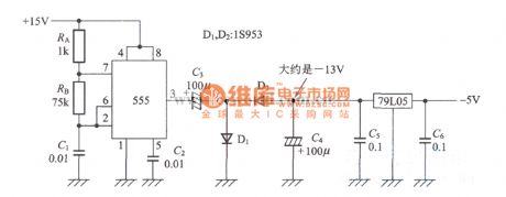
Obtaining Exact -5V from +15V Power Supply Circuit
Published:2011/5/17 7:59:00 Author:Joyce | Keyword: Obtaining Exact -5V from +15V Power Supply
View full Circuit Diagram | Comments | Reading(660)
Single-Phase Bridge Rectifier Circuit
Published:2011/5/17 7:26:00 Author:Robert | Keyword: Single-Phase, Bridge, Rectifier
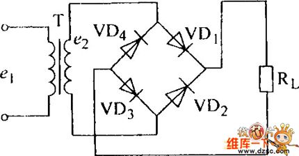
The Single-Phase Bridge Rectifier Circuit is shown below.
(View)
View full Circuit Diagram | Comments | Reading(1646)
Adaptive adjustable power supply circuit diagram
Published:2011/5/16 20:19:00 Author:Ecco | Keyword: Adaptive , adjustable , power supply
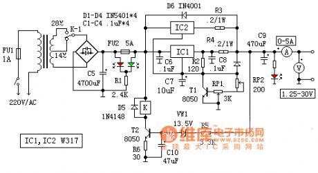
In the circuit, the T2, D5, VW1, R5, R6, C10 and K constitute adaptive switching action circuit. When the output is lower than 14V, VW1 stops due to lacking of sufficient breakdown voltage, the circuit has no current, T2 cuts off, K does not pull, the contact K is in the normal position, the input current is AC 14V. Conversely when the output voltage is higher than 14V, VW1 and T2 are conducted, the relay K pulls in, 28V AC is put in the circuit. This ensures that the input voltage and output voltage difference is not greater than 15V, then, the typically value of W317 output current is 2.2A.
(View)
View full Circuit Diagram | Comments | Reading(916)
Bridge Rectifier Circuit
Published:2011/5/17 6:57:00 Author:Robert | Keyword: Bridge, Rectifier
The Bridge Rectifier Circuit is shown below.
(View)
View full Circuit Diagram | Comments | Reading(941)
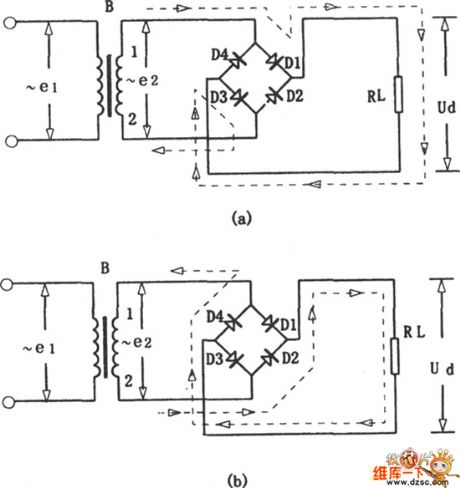
The single power changing into dual power circuit diagram by TDA2030
Published:2011/5/16 21:58:00 Author:Ecco | Keyword: single power , dual power
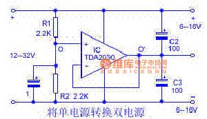
The circuit is shown as the chart, R1 and R2 with the equal resistance form a voltage divider, so that the upper and lower voltage are equal. The mid-point of the divider is connected to the op amp inverting input end, the op amp is connected as a voltage follower, so that the potential on O 'and O side is equal. O 'side is the virtual point, the place connected to input supply must be isolated. If the bipolar power supply is directly out from the R1, R2, the resistance of source is higher, the load capacity is poor, the practical value is little. After using the operational amplifier, two output powers have low internal resistance, the load capacity is strengthened.
(View)
View full Circuit Diagram | Comments | Reading(3584)
circuit diagram of electron gun DC high voltage power supply
Published:2011/5/17 8:21:00 Author:Ariel Wang | Keyword: electron gun, DC, high voltge

The circuit diagram of electron gun DC high voltage power supply is as below:
(View)
View full Circuit Diagram | Comments | Reading(1142)
BA6227-the speed-stable integrated circuit
Published:2011/5/13 7:12:00 Author:Borg | Keyword: speed-stable, integrated circuit
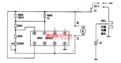
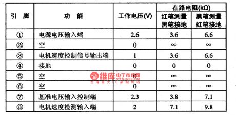
BA6227 is a speed-stable integrated circuit produced by Toyo Corp.,Japan, which is used to drive and regulate the motor.1.the typical circuit of BA6227 The typical application circuit of BA6227 chips is as shown in Figure 1.
Figure 1 The typical application circuit of BA6227 chipsBA6227 is in 8-lead dual-line package, whose pin functions and data are listed in Table 1.
Table 1 pin functions and data of BA6227 chips (View)
View full Circuit Diagram | Comments | Reading(2019)
Multi-purpose automatic charger circuit diagram
Published:2011/5/16 21:43:00 Author:Ecco | Keyword: Multi-purpose , automatic , charger
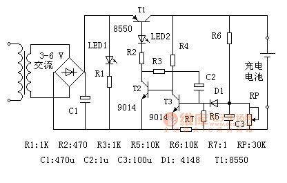
The circuit is designed for the single Ni-MH battery. In the figure: the electric supply is transformed by the transformer, rectified by the full-bridge, filtered by capacitor C1 and then it becomes DC current. LED1 is the power indicator, LED2 is the charging indicator light, T1 is the charging control transistor, which operates in the switching state; T2, T3 and capacitor C2 form a single stable trigger. R6 and RP constitutes a limited pressure sampling circuit, R7 is limiting the sampling resistor.
When the circuit gets power, if it does not connect to the battery, transistor T2 cuts off because of no base voltage, transistor T1 is also off, there is no voltage output. At this point only the power indicator light LED1 is lit.
(View)
View full Circuit Diagram | Comments | Reading(2163)
constant-current timing charging circuit
Published:2011/5/16 20:05:00 Author:Christina | Keyword: constant-current, timing, charging
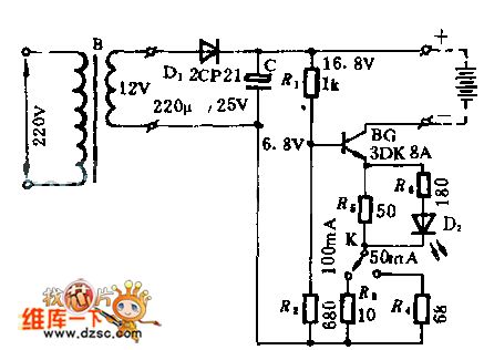
The 12V AC voltage is rectified by the D1 and becomes the 16.8V DC charging voltage, the R1,R2 and the constant-current source tube BG supply the base bias. R3,R4 and R5 are the current limiting resistor to limit the charging current between 50 to 100 mA, and it is switched by K.
This circuit is very simple, and has no timeout protection measures, so you need to notice the timing.
(View)
View full Circuit Diagram | Comments | Reading(711)
Cadmium nickel battery charging circuit
Published:2011/5/16 20:29:00 Author:Christina | Keyword: Cadmium, nickel, battery charging
In this circuit, R1 is the 10Ω resistance, R2 is the 200Ω resistance. When the switch closes up, the charging current is 60mA (constant-current); when the switch closes down, the charging current is 3mA (constant-current). The total pressure drop of the silicon diode CR1 and CR2 are 1.2V, but Q1's launch pressure drop is 0.6V, so R1 or R2's net pressure drop is 0.6V. The 0.6V is divided by the required charge current, we get the resistance of R1 or R2. The LED indicates the charging circuit's working state.
(View)
View full Circuit Diagram | Comments | Reading(622)
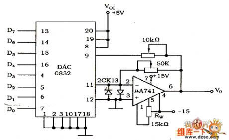
D/A converter DAC0832 circuit
Published:2011/5/16 9:26:00 Author:Christina | Keyword: D/A, converter
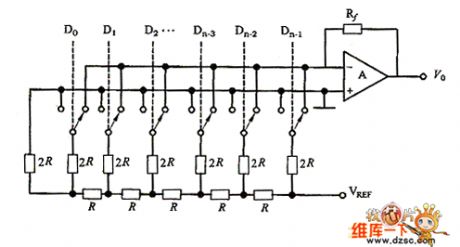
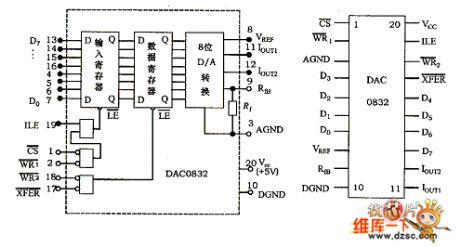
The DAC0832 uses the monolithic dc output type 8 digit/mode converter with the CMOS technology. As the figure 1 shows, this device is composed of the inverted T-type R-2R resistor network, the analog switch, the operational amplifier and the reference voltage VREF. The operational amplifier's output analog quantity V0 is:
Figure 1
One 8-bit D/A converter has eight input ports (each input port is one of the eight binary number) and one analog output port. The input can have 28=256 different binary configurations, the output is one of the 256 voltages, this means the output voltage is not any value of the whole voltage range, it can only be 256 possible values. Figure 2 shows the DAC0832's logic diagram and pin arrangement.
Figure 2
Figure 3
(View)
View full Circuit Diagram | Comments | Reading(4311)
LED slow charging circuit
Published:2011/5/16 22:22:00 Author:Christina | Keyword: LED, slow charging
The LED uses the NSL4944 which is produced by the National Smiconductor Company, this LED has the constant current characteristic. After the AC power input, by getting through the half-wave rectifier charging circuit, you can charge the 1.5~6.0V battery slowly. (View)
View full Circuit Diagram | Comments | Reading(708)
| Pages:224/291 At 20221222223224225226227228229230231232233234235236237238239240Under 20 |
Circuit Categories
power supply circuit
Amplifier Circuit
Basic Circuit
LED and Light Circuit
Sensor Circuit
Signal Processing
Electrical Equipment Circuit
Control Circuit
Remote Control Circuit
A/D-D/A Converter Circuit
Audio Circuit
Measuring and Test Circuit
Communication Circuit
Computer-Related Circuit
555 Circuit
Automotive Circuit
Repairing Circuit