
Index 222
Hitachi F1 microchip power supply circuit
Published:2011/5/25 6:18:00 Author:Christina | Keyword: Hitachi, F1, microchip, power supply
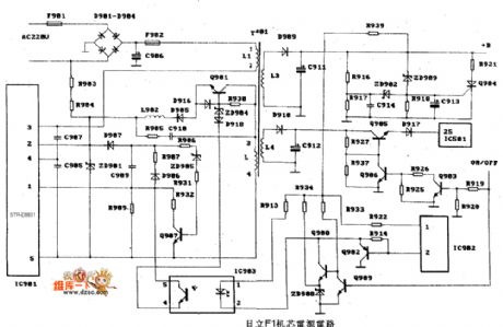
The Hitachi F1 microchip power supply circuit is as shown:
(View)
View full Circuit Diagram | Comments | Reading(1502)
DOHER (DVD) power supply circuit
Published:2011/5/30 3:12:00 Author:Christina | Keyword: DOHER, DVD, power supply
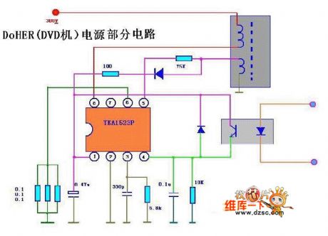
The DOHER (DVD) power supply circuit is as shown:
(View)
View full Circuit Diagram | Comments | Reading(2579)
Bubugao VCD-AB115 switch power supply circuit
Published:2011/5/30 3:20:00 Author:Christina | Keyword: Bubugao, switch, power supply
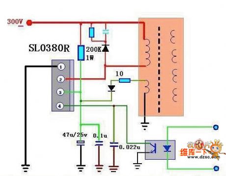
The Bubugao VCD-AB115 switch power supply circuit is as shown:
(View)
View full Circuit Diagram | Comments | Reading(993)
8156 type Amoi DVD power supply circuit
Published:2011/5/30 3:13:00 Author:Christina | Keyword: Amoi, DVD, power supply
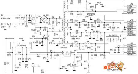
The 8156 type Amoi DVD power supply circuit is as shown:
(View)
View full Circuit Diagram | Comments | Reading(2844)
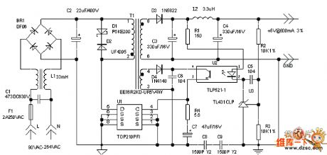
4W switch-type 5V regulated DC power supply circuit
Published:2011/5/29 7:25:00 Author:chopper | Keyword: 4W, switch-type, 5V, regulated DC power supply
View full Circuit Diagram | Comments | Reading(1196)
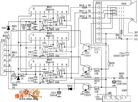
The circuit based on optic radiation TAD6101
Published:2011/5/30 7:14:00 Author:Ariel Wang | Keyword: optic radiation
View full Circuit Diagram | Comments | Reading(744)
the power-supply circuit-fixed of adjustable and DC part 14
Published:2011/5/29 20:14:00 Author:Ariel Wang | Keyword: adjustable, DC, circuit-fixed
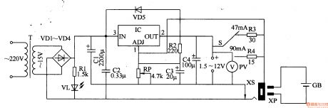
The working principle of circuit
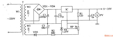
This DC power-supply circuit-fixed is made up by the circuit of dropped-down and commutated voltage,steady output circuit and constant current output circuit.See chart 5-18 below.
After the 220V AC voltage is dropped down through T,commutatedthrough VDl-VD4.It is connected to the third foot (the edge of input) of IC directly,as the input voltage of regulator.It is connected to VL through Rl.And then it light VL up.
When the plug XPisnot plugged into the socket XS,the 15VAC voltage on the second winding of T is commutated through VDl-VD4,filtered through Cl and numberous regulation.Then it outputssteady DC voltage through the second foot of IC. You can adjust the resistence of RP,in order to make the output DC voltage contiously adjustable between 1.25-12V.
(View)
View full Circuit Diagram | Comments | Reading(512)
Power-supply of adjustable DC steady voltage part 11
Published:2011/5/29 20:15:00 Author:Ariel Wang | Keyword: adjustable, DC , steady voltage
After SLis gotten through, HL is lighted up.The 220V AC voltage is dropped down through T,commutated through UR,filtered through C1 and C2 and regulated through voltage regulation output circuit.It generates 5-30V DC voltage.You can adjust the resistance of RP2(output voltage fine adjustment control ) and RP3(output voltage coarse adjustment ). It can change the conduction ability of Vl-V4 and the voltage of emitter (b,e pole) ,then it wil change the output voltage.When it's over loaded by some reasons,try to make the output electric current increase to a certain level.Try to conduct V5,to stop V7 ,to make the 3 feet output voltage of IC 0V and to stop Vl-V4.Then the output voltage is disappeared.
(View)
View full Circuit Diagram | Comments | Reading(2060)
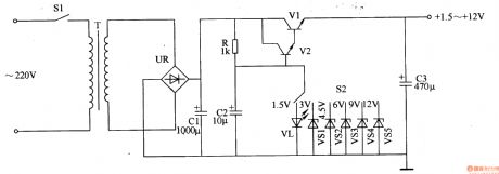
Power-supply of adjustable DC steady voltage part 8
Published:2011/5/29 23:26:00 Author:Ariel Wang | Keyword: adjustable, DC , steady voltage

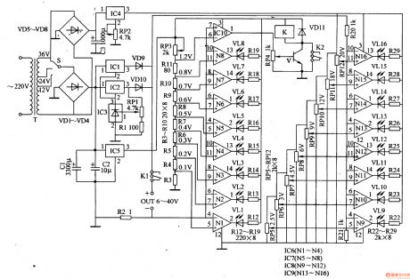
The 220V AC voltage is dropped down through T,commutated through VD1-VD4,filtered through C1 and C.And it is regalated by lCl-IC3,RPl,Rl,VDg and VDlO.Then it goes through the contactor K1 of electric relay K .It provides load(withelectrical equipment) .Or it may charge up storage battery. It is voltage-regulated to +6V through IC5, being as the working voltage for IC6,1C7,IClO and K . The AC voltage regulated through T should commutate through VD5-VD.It filtered through C3 and voltage-regulated through IC4 and RP2.It generates +20V voltage as the working power-supply for IC5 and IC9. In order not to make the voltage drop too much when the voltage goes through the input end to the output end .You can use voltage option switch S to choose the voltage of 12V,24V and 36V AC secondary side of T.Adjust the resistance of RP1.Then its output end (OUT) can generate DC voltage of 6-40V.
(View)
View full Circuit Diagram | Comments | Reading(643)
Power-supply of adjustable DC steady voltage part 9
Published:2011/5/29 20:15:00 Author:Ariel Wang | Keyword: adjustable, DC , steady voltage
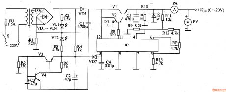
Over current protected circuit is made up by the 13th foot internal circuit of IC,transistor V3,V4,resistor R1,R3-R6,capacitor C2-C4,diode VD7 and LED VL2.When switch S of power-supplyis gottenthrough,the 220V AC voltage is dropped down through T,commutated through VDl-VD4.It lights VL1 up through R2.It is connected to emitter of V3 through R4.And it lights VL2 up at the same time.It is isolated and filtered through VD5 and C1.It generates the voltage of around +23V voltage. And it is connected to the 12th foot of IC and collector of V1. The +23V voltage is regulated and adjusted through circuit.It outputs steady DC voltage from the emitter of V1. You can adjust the resistance of RP,in order to make the output voltage change continuously between 0-+20V.
(View)
View full Circuit Diagram | Comments | Reading(3795)
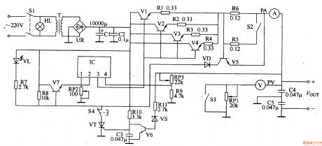
Power-supply of adjustable DC steady voltage part 7
Published:2011/5/29 20:16:00 Author:Ariel Wang | Keyword: adjustable, DC, steady voltage
(View)
View full Circuit Diagram | Comments | Reading(587)
Power-supply of adjustable DC steady voltage part 13
Published:2011/5/29 20:14:00 Author:Ariel Wang | Keyword: adjustable, DC, steady voltage
&nbs (View)
View full Circuit Diagram | Comments | Reading(770)
power-supply circuits-fixed of numerical control and DC part 1
Published:2011/5/29 20:13:00 Author:Ariel Wang | Keyword: mumerical control, DC, circuits-fixed
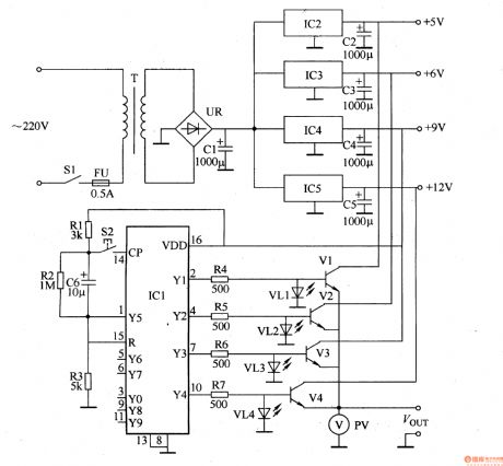
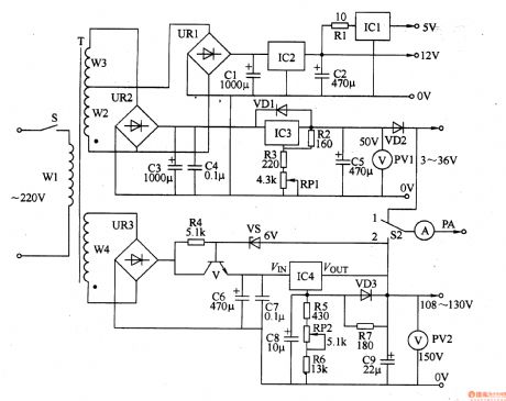
After SI is being connected, 220VACvoltage is dropped down through T, commutated through UR and filtered through C1.It generates +18V DC voltage. The voltage is steady through IC2,IC3,IC4 and IC5. Then it generates the voltage of 5V,+6V,+9V and +l2V. These four groups are put on V1-V4 collectors. The voltage of +gV is being as working power supply as IC. After ICl electrified and reset, the YO edge(3 feet)is high power level output,Yl-Y9 is low power level output. Press S2,the CP edge (14 feet) will output a bigger counting pulse. The Yl egde wil output high power level,while YO edge turns back to low power level. Press S2 continuously,the YO-Y4 edge of ICl will output high power level one by one.
(View)
View full Circuit Diagram | Comments | Reading(833)
power-supply circuit-fixed of adjustable DC
Published:2011/5/25 0:10:00 Author:Ariel Wang | Keyword: circuit-fixed, adjustable, DC
(View)
View full Circuit Diagram | Comments | Reading(863)
Power-supply of adjustable DC steady voltage
Published:2011/5/25 23:26:00 Author:Ariel Wang | Keyword: adjustable, DC, steady voltage
(View)
View full Circuit Diagram | Comments | Reading(941)
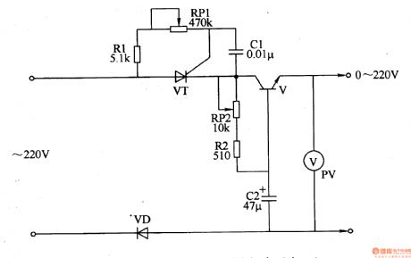
Portable SCR charger circuit
Published:2011/5/24 2:43:00 Author:John | Keyword: Portable SCR charger
Charger directly uses 220V AC power supply. It achieves the output voltage adjustment starting from 0V by controlling the triggering circuit. It is suitable for charging 12V-220V battery (s).
The main control circuit is composed by the fuse FU, ammeter and SCR VS. When the battery, as well as the batteries, requiring being charged is connected, the SCR VS gains trigger pulse. Conduction angle of VS is regulated by pulses with different width. And the RP can be adjusted to meet the charge of different battery or batteries within different charging current or voltage. (View)
View full Circuit Diagram | Comments | Reading(4836)
Maintenance-free sealed micro-battery circuit
Published:2011/5/24 3:02:00 Author:John | Keyword: micro-battery
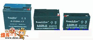
Micro-battery described in this article has the following characteristics: (1) There is no liquid flow inside, so that it can be placed in any direction without influencing the function. (2) There is no need for acid-supply and other maintenance work during the entire applying process. The battery surface is clean and not damp. (3) Gases produced by the charging process can be absorbed by a special anode. The overall sealed performance can be achieved. So it is not necessary to worry about the corrosion and pollution to electrical equipment.(4) Its charge and discharge cycles can be over more than 300 times within proper use. And the service life is up to 3 years. (5) It has very low ability to internal self-discharge. Its rate for self-discharging is less than 1%. (View)
View full Circuit Diagram | Comments | Reading(1108)
active load circuit
Published:2011/5/24 5:15:00 Author:John
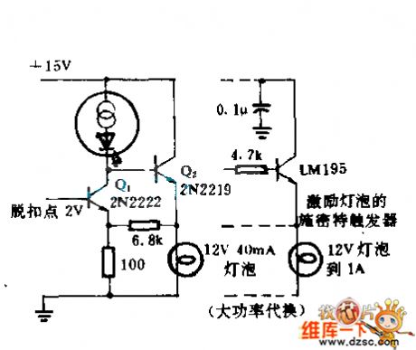
Q1 and Q2 constitute a Schmitt trigger. Constant current LED NSL4944 is regarded as load collector, providing output of 12V and 40mA. When the bulb is not conducting with Q2, most current of the light-emitting diode flows through the resistor with resistance of 100Ω. So the voltage in trigger circuit is limited to 2V. When the control signal saturates Q1, Q2 supplies the lamp with voltage of about 1V. Such plays a role of preheating and reducing voltage for starting. Q2 is conducted to light the bulb.
(View)
View full Circuit Diagram | Comments | Reading(958)
Rechargeable battery technology and charging method circuit
Published:2011/5/24 1:48:00 Author:John | Keyword: Rechargeable battery
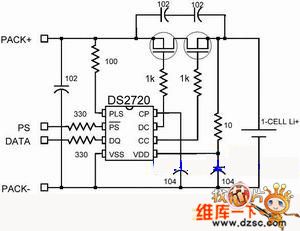
Battery applications have never been so extensive. Batteries are becoming smaller and lighter. And they can accommodate more energy in every unit volume. The main driving force of the battery is mainly from the development of portable devices (mobile phones, laptop computers, camcorders, MP3 players).
This article outlines the battery charging methods and modern technology, in order to make people better understand the batteries used in portable devices. These include battery chemistry description for nickel-cadmium (NiCd), nickel metal hydride (NiMH) and lithium-ion (Li +). This article also describes protection devices for single-cell lithium ion and lithium-ion polymer battery. (View)
View full Circuit Diagram | Comments | Reading(1110)
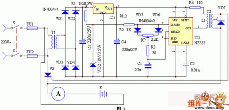
SCR automatic constant current charger circuit
Published:2011/5/24 2:31:00 Author:John | Keyword: automatic constant current charger
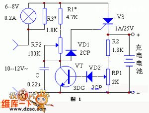
Principle of the circuit is shown in the figure. When it starts to charge, the voltage on two ends of the battery is low. Such is not enough to turn the transistor VT on. Phase-shift circuit formed by RC is to provide trigger current for SCR. The angle of phase-shift is determined by the RP2. SCR deadlines at negative half-cycle moment. Therefore, SCR charges by utilizing the half-wave silicon controlled rectifier to the battery generator. RP2 can be adjusted to adjust the charge current. The maximum charge current is set by R1. Indicating light is string in the circuit to indicate charging status and charge current. R3 is to adjust the brightness of light.
(View)
View full Circuit Diagram | Comments | Reading(3963)
| Pages:222/291 At 20221222223224225226227228229230231232233234235236237238239240Under 20 |
Circuit Categories
power supply circuit
Amplifier Circuit
Basic Circuit
LED and Light Circuit
Sensor Circuit
Signal Processing
Electrical Equipment Circuit
Control Circuit
Remote Control Circuit
A/D-D/A Converter Circuit
Audio Circuit
Measuring and Test Circuit
Communication Circuit
Computer-Related Circuit
555 Circuit
Automotive Circuit
Repairing Circuit