
Index 225
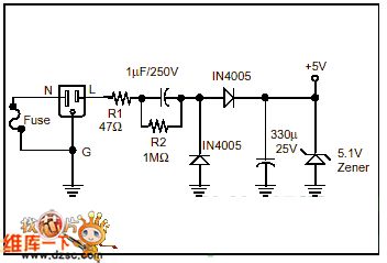
Power supply principle circuit without transformer
Published:2011/5/17 1:26:00 Author:Christina | Keyword: Power supply, principle, transformer
View full Circuit Diagram | Comments | Reading(1827)
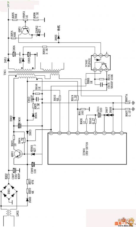
Hitachi A3P-B2 power supply (A4) circuit
Published:2011/5/16 22:22:00 Author:Christina | Keyword: Hitachi, power supply
View full Circuit Diagram | Comments | Reading(733)
Four-tone circuit
Published:2011/5/17 1:12:00 Author:Christina | Keyword: Four-tone
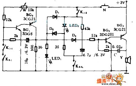
This circuit can send out four kinds of single tones and four kinds of flash effects by using two switches' four different combinations.
BG1 and BG2 are the clearance oscillating circuits, you can adjust the oscillation frequency by using W; BG3, BG4 and Y are the audio oscillating circuits, and you can change the tone by changing C. K1-1, K2-1 and K1-2, K2-2 are two switches, when they are 00,01,10,11, the circuit is in four states and can produce four kinds of single tones and flash effects.
(View)
View full Circuit Diagram | Comments | Reading(632)
Three time base window circuits
Published:2011/5/16 19:31:00 Author:Christina | Keyword: Three, time base window
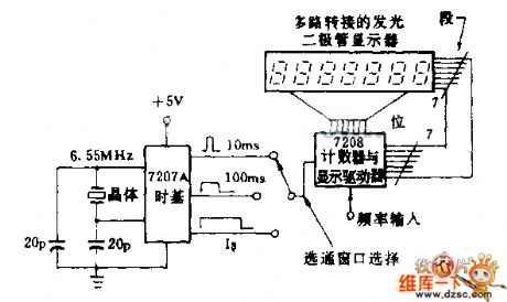
The 7207A crystal control timer produces three accurate selective passing windows; 10ms,100ms and 1S. This windows can be used as the time base of the frequency counter, the approval time standard or the selective passing timer signal.
(View)
View full Circuit Diagram | Comments | Reading(620)
Power supply monitoring circuit
Published:2011/5/16 19:03:00 Author:Christina | Keyword: Power supply, monitoring
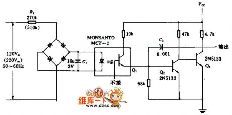
The low-level voltage logic part is separated with the power supply by the optocoupler. If there is something wrong with the citcuit, the output voltage level reduces to the logic voltage level to adjust the output of the trigger and to close the whole circuit. The response time of this circuit is 2ms, when the AC grid voltage passes zero normally, there is on influence to the circuit. The power consumption of this circuit is 50 mW.
(View)
View full Circuit Diagram | Comments | Reading(738)
The limiter circuit and the rectifier circuit
Published:2011/5/16 10:05:00 Author:Christina | Keyword: limiter, rectifier
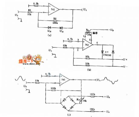
Figure (a) is the circuit of the voltage limiter, the forward limited pressure and the reverse limited pressure are: the regulator's regulator-value UZ plus the diode's positive pressure drop 0.7V. Resistance R1 and R2 decide the amplifier system, when the output voltage UA ≤±(UZ)+0.7 V, the VO≈R2/R1.
(View)
View full Circuit Diagram | Comments | Reading(906)
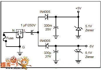
A positive and negative output adjustable voltage-stabilized power supply circuit
Published:2011/5/16 8:24:00 Author:Christina | Keyword: positive, negative, output adjustable, voltage-stabilized, power supply
A positive and negative output adjustable voltage-stabilized power supply circuit:
(View)
View full Circuit Diagram | Comments | Reading(981)
4W switch type DC manostat circuit
Published:2011/5/16 5:45:00 Author:Christina | Keyword: 4W, switch type, DC manostat
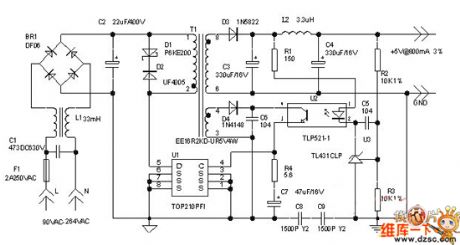
The 4W switch type DC manostat circuit is as shown:
(View)
View full Circuit Diagram | Comments | Reading(1406)
RC reset circuit input/output characteristic circuit
Published:2011/5/16 4:40:00 Author:Christina | Keyword: RC reset circuit, input/output, characteristic
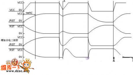
The RC reset circuit input/output characteristic circuit is as shown:
(View)
View full Circuit Diagram | Comments | Reading(574)
interphone quick charger circuit
Published:2011/5/16 4:38:00 Author:Christina | Keyword: interphone, quick charger
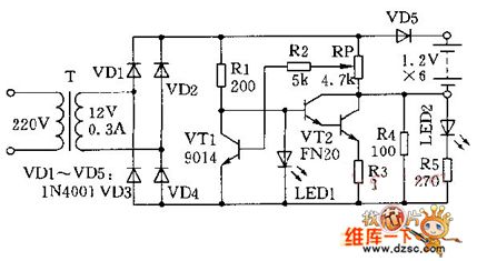
The interphone quick charger circuit is as shown:
(View)
View full Circuit Diagram | Comments | Reading(684)
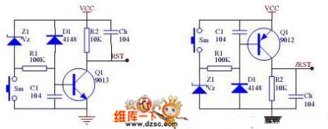
Reset circuit with the voltage monitoring function
Published:2011/5/16 4:37:00 Author:Christina | Keyword: Reset circuit, voltage monitoring function
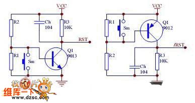
The Reset circuit with the voltage monitoring function is as shown:
(View)
View full Circuit Diagram | Comments | Reading(680)
The simplest Li-ion battery standard charger circuit
Published:2011/5/16 4:25:00 Author:Christina | Keyword: simplest, Li-ion battery, standard charger
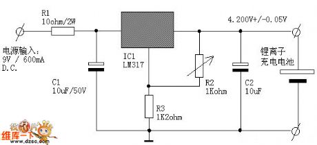
The The simplest Li-ion battery standard charger circuit is as shown:
(View)
View full Circuit Diagram | Comments | Reading(2418)
Practical reset monitoring circuit
Published:2011/5/16 4:28:00 Author:Christina | Keyword: Practical, reset, monitoring circuit
View full Circuit Diagram | Comments | Reading(549)
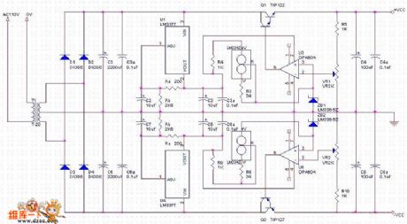
UPS circuit with LM3524D
Published:2011/5/14 23:24:00 Author: | Keyword: LM3524D, UPS circuit
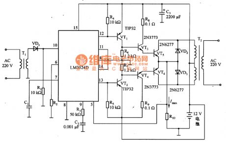
LM3524D is a kind of switch power supply controller which uses PWM operate mode. In the working mode, the pin 12 and pin 13 of LM3524D output pulse signals with the phase difference of 180°, whose voltages are amplified through VT1 and VT2 and then the electric currents are stimulated to be amplified by VT3 and VT4. As a result, both of the two processes drive the VT5 and VT6 to amplify the power of the pulse signals. The power amplifier VT5 and VT6 generates 12V square AV voltages on the one side of T2 transformer according to the alternating of the pulse signals outputting by VT1 and VT2.between turning on and turning off. After being stepped up, the square AV voltages are changed to 220 V AV voltages and are output through the other side of the transformer T2, which offer power supply for the load. The operating frequency of this circuit is decided by R2 and C1.VD2 and VD3 in this circuit is used to prevent the power amplifier from flowing through the current with a opposite direction. (View)
View full Circuit Diagram | Comments | Reading(3397)
Adjustable car battery charger circuit
Published:2011/5/16 4:22:00 Author:Christina | Keyword: Adjustable, car battery charger
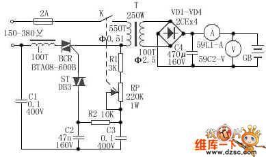
The Adjustable car battery charger circuit is as shown:
(View)
View full Circuit Diagram | Comments | Reading(11694)
DplO4C-the integrated circuit of chief power supply thick films
Published:2011/5/13 20:49:00 Author:Borg | Keyword: integrated circuit, power supply
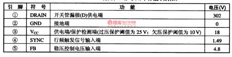
DplO4C-is an integrated circuit of chief power supply thick films, which is widely used in SAMSUNG computer color screens.1.function featuresDPIO4C contains a switch activating circuit, switch circuit, supply and protection circuit, line frequency activating signal processing circuit, stable control circuit and other additional function circuits.2.pin functions and dataDPlO4C is in 5-lead single in-line package, which is used in color screens of SAMSUNG 743DFS. The pin functions and data of it are listed in Table 1-1.
(View)
View full Circuit Diagram | Comments | Reading(539)
Non-isolated 12V DC power supply circuit diagram composed of UCC3889
Published:2011/5/13 3:22:00 Author:Ecco | Keyword: Non-isolated , 12V , DC , power supply
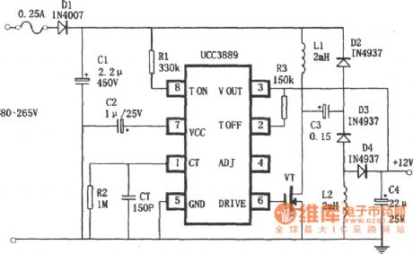
Non-isolated 12V DC power supply circuit diagram composed of UCC3889 is shown as the chart, output poweris 1W, the minimum switching frequencyis 100kHz, the total efficiency is about 50%.
(View)
View full Circuit Diagram | Comments | Reading(3501)
BA6247N-an motor-driven integrated circuit
Published:2011/5/13 1:18:00 Author:Borg | Keyword: motor-driven, integrated circuit
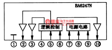
BA6247N is an motor drive integrated circuit of 2-channel 2-way control, which is produced by Toyo, Janpan. It is often used in CD, VCD,SVCD and DVD players as drivers of motors and rolling discs.1.the internal circuitBA6247N contains logic control circuits and drive circuits, whose internal circuit is as shown in Figure 1.
Figure 1 the internal circuit of BA6247N
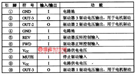
2. Pin functionsBA6247N is in 10-lead single in-line package, whose pin functions are listed in Table 1.
(View)
View full Circuit Diagram | Comments | Reading(578)
Digital controlled adjustable integrated regulated power supply circuit diagram
Published:2011/5/10 22:18:00 Author:Rebekka | Keyword: Digital controlled, adjustable integrated regulated power supply
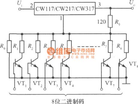
Here is the diagram of digital controlled adjustable integrated regulated power supply circuit composed of CW117, CW217 and CW317.
The figure shows the digital control adjustable integrated regulated power supply. Digital control input is 8-bit binary code. Reasonable choice for the resistance resistance R0 ~ R8 can get the CNC adjustable integrated regulated power supply that its output voltage is 2.5 ~ 120V and stepping value is 0.5V. The precision requirement of resistance R0 ~ R8 is high. The requirement of the high binary code resistance is highest. Such as when the accuracy of R0 and R8 is ± 0.1%, the output precision of 120V high-voltage is about 0.5V. When the 8-bit binary code is 00000000 , the transistor VT1 ~ VT8 all stop, the output voltage is maximum. When the 8-bit binary code shows 11111111 , the transistor VTl ~ VT8 are all turned on, R0 ~ R8 9 resistors in parallel is equivalent to the resistance R2 of the standard circuit, then the output voltage is the lowest. Adjust the output voltage to make the input and output voltage of the integrated regulator is less than the allowed value(40V). (View)
View full Circuit Diagram | Comments | Reading(1665)
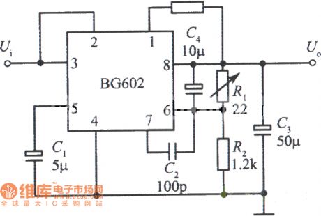
Low ripple integrated circuit diagram 1 composed of BG602
Published:2011/5/13 1:23:00 Author:Ecco | Keyword: Low ripple , integrated circuit
View full Circuit Diagram | Comments | Reading(559)
| Pages:225/291 At 20221222223224225226227228229230231232233234235236237238239240Under 20 |
Circuit Categories
power supply circuit
Amplifier Circuit
Basic Circuit
LED and Light Circuit
Sensor Circuit
Signal Processing
Electrical Equipment Circuit
Control Circuit
Remote Control Circuit
A/D-D/A Converter Circuit
Audio Circuit
Measuring and Test Circuit
Communication Circuit
Computer-Related Circuit
555 Circuit
Automotive Circuit
Repairing Circuit