
Filter Circuit
Index 11
DC_LEVEL_SHIFTER_FOR_AF
Published:2009/7/2 9:13:00 Author:May
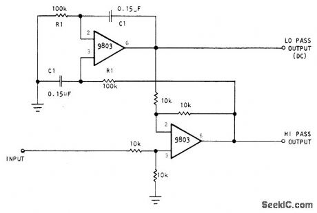
Circuit using optical Electronics 9803 opamps separates AF input signal into two outputs. Low-pass output contains DC to 10 Hz, and high-pass output has frequency content above 10 Hz to upper frequency limit approaching 10 MHz for opamp used. Dynamic output impedance of both outputs is less than 1 ohm. Both outputs have DC continuity. DC output of high-pass terminal is equal to offset voltage of integrator. DC output of low-pass terminal equals DC input plus offset voltages of both opamps.- Automatic DC Level Shifter, Optical Electronics, Tucson, AZ, Application Tip 10226. (View)
View full Circuit Diagram | Comments | Reading(1063)
50_Hz_WIEN_BRIDGE_NOTCH_FILTER
Published:2009/7/2 8:52:00 Author:May
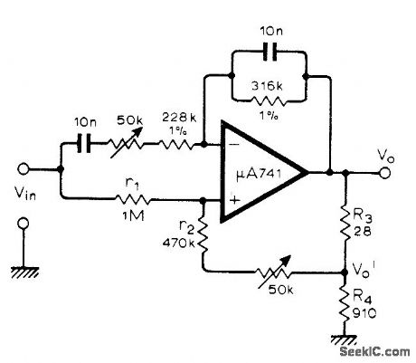
Uses opamp in circuit having essentially zero output impedance, making additional buffer amplifier unnecessary. Article gives design theory and covers many other types of notch filters.-Y.Nezer, Active Notch Filters, Wireless World, July 1975, p 307-311. (View)
View full Circuit Diagram | Comments | Reading(1918)
FREQUENCY_TRACKING_BANDPASS
Published:2009/7/2 8:49:00 Author:May
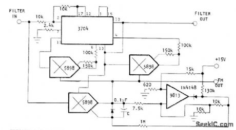
High-Q active bandpass filter automatically tracks input signal frequency over 10:1 range in presence of noise.When signal goes outside tracking range, circuit sweeps between low- and high-frequency limits until suitable signal reappears. Circuit is basically voltage-controlled bandpass filter using Optical Electronics 3704 active filter with 5898 analog multipliers. 9813 opamp connected as Schmitt trigger is main element of scanning circuit. Frequency range is 160 to 1600 Hz, and FM bandwidth of error-voltage output is 20 Hz.- Frequency Tracking Active Filter, Optical Electronics, Tucson, AZ, Application Tip 10270. (View)
View full Circuit Diagram | Comments | Reading(1191)
1_kHz_MULTIPLE_FEEDBACK_BANDPASS
Published:2009/7/2 8:47:00 Author:May
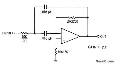
Single 741 or equivalent opamp is suitable for applications where bandwidth is less than 100%.Gain is fixed at -2Q2, where Q is reciprocal of damping d and ranges from less than 1 to above 100. Q is changed by varying ratio of input and feedback resistors while keeping their product constant. For Q of 3, feedback resistor should be 36 times value of input resistor.-D. Lancaster, Active-Filter Cookbook, Howard W. Sams, Indianapolis, IN, 1975, p 150-154. (View)
View full Circuit Diagram | Comments | Reading(961)
1_Hz_STATE_VARIABLE_FILTER
Published:2009/7/2 8:46:00 Author:May
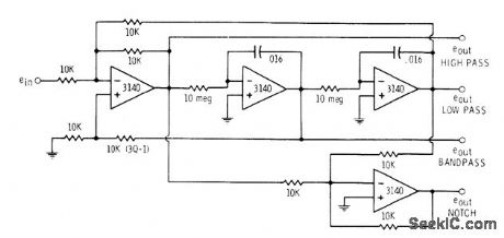

Universal filter has simultaneous low-pass, bandpass, high-pass, and notch outputs all with cutoff frequency of 1 Hz. To scale circuit up to 1-kHz cutoff, replace 10-megohm resistors with 10K.-D.Lancaster, CMOS Cookbook, Howard W.Sams, Indianapolis, IN, 1977, p 343-344. (View)
View full Circuit Diagram | Comments | Reading(944)
20_kHz_BANDPASS
Published:2009/7/2 8:44:00 Author:May
Provides bandwidth of 2000 Hz and midband gain of 1 for applications requiring narrow-bandwidth bandpass active filter. Design procedure is given.- Audio Handbook, National Semiconductor, Santa Clara, CA, 1977, p 2-52-2-53. (View)
View full Circuit Diagram | Comments | Reading(1046)
3_1_TRACKING_FILTER
Published:2009/7/2 8:40:00 Author:May
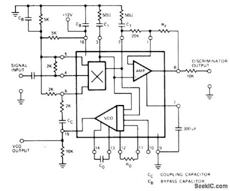
Connection shown for Exar XR-215 PLL IC tracks input signal over 3:1 frequency range centered on free,running frequency of VCO. Tracking range is maximum when pin 10 is open. R0 is typically between 1K and 4K.C1 is between 30 and 300 times C0 where timing capacitor C0 depends on center frequency. System can also be operated as linear discriminator or analog frequency meter covering same 3:1 change of input frequency. RF can be 36K.- Phase-Locked Loop Data Book, Exar Integrated Systems, Sunnyvale, GA, 1978, p 21-28. (View)
View full Circuit Diagram | Comments | Reading(888)
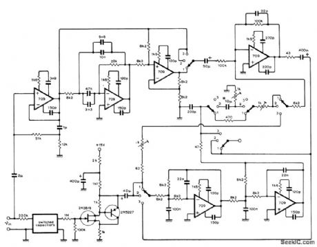
2_20_kHz_SELF_TUNING_BANDPASS
Published:2009/7/2 8:13:00 Author:May
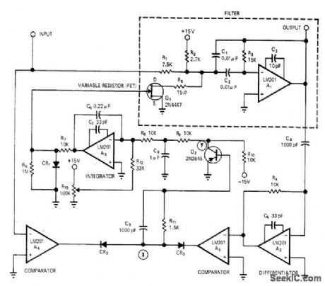
Center frequency of filter is automatically adjusted to track signal frequency, for optimum noise rejection when input frequency varies over wide range as it does with many types of vibrating transducers.Requires no reference frequency and no intemal oscillator or synchronizing circuits. Flequency range can be extended in decade steps by capacitor switching. When filter is not tuned to input frequency, phase shift is not 180° and phase detector applies error signal to gate of FET to control its drain-source resistance. Phase detector A4-A5-CR2-CR3 and FET form part of negative-feedback loop around filter, so error in phase changes resistance of FET and thereby retunes filter, Article gives design equations, operational details, and waveforms at various points in circuit.-G. J. Deboo and R.C. Hedlund, Automatically Tuned Filter Uses IC Operational Amplifiers, EDN/EEE Magazine, Feb.1, 1972, p 38-41. (View)
View full Circuit Diagram | Comments | Reading(1050)
75O_Hz_SIXTH_ORDER_BANDPASS
Published:2009/7/2 8:12:00 Author:May
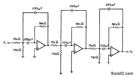
Provides passband gain of 6 (15.6 dB) and Q of 8.53 by cascading three identical second-order filter sections. Each section uses multiple feedback.-H. M.Berlin, Design of Active Filters, with Experiments, Howard W. Sams, Indianapolis, IN, 1977, p 147-148. (View)
View full Circuit Diagram | Comments | Reading(918)
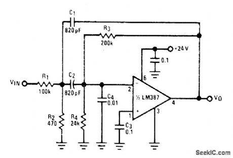
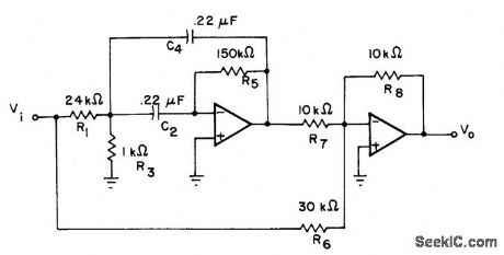
150_Hz_HIGH_PASS
Published:2009/7/2 8:10:00 Author:May
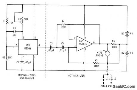
Circuit includes variable high-frequency source supplying triangle-wave input to filter for demonstrating high-pass action. If long supply leads cause oscillation, connect 0.1-μF capacitors between ground and supply pins 4 and 7 as shown.-F. M. Mims, lntegrated Circuit Projects, Vol. 4, Radio Shack, Fort Worth, TX, 1977, 2nd Ed., p 87-94. (View)
View full Circuit Diagram | Comments | Reading(1040)
300_3000_Hz_WIDEBAND
Published:2009/7/2 8:07:00 Author:May
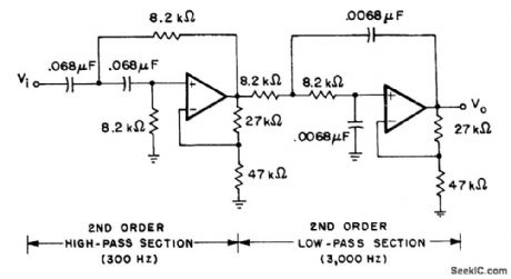
Used in voice communication systems where signals below 300 Hz and above 3000 Hz must be rejected. Secondorder Butterworth stopband responses are achieved by combining low-pass and high-pass sections of equal-component voltage-controlled voltage-source filters. Overall passband gain is 8 dB Opamps can be 741.-H. M. Berlin, Design of Active Filters, with Experiments, Howard W. Sams, Indianapolis, IN, 1977, p 148-151. (View)
View full Circuit Diagram | Comments | Reading(1526)
480_kHz_LOW_PASS
Published:2009/7/2 8:07:00 Author:May
Butterworth low-pass active filter uses pair of dual opamps with external resistors and capacitors to give corner frquency of 480 kHz and output impedance level of 1K. Article presents design procedure in detail and gives frequency response curve.-L. T.Burton and D.Treleaven, Active Filter Design Using Generalized Impedance Conveners, EDN Magazine,Feb.5,1973, p 68-75. (View)
View full Circuit Diagram | Comments | Reading(893)
NARROW_BANDPASS_FOR_SPEECH
Published:2009/7/2 7:36:00 Author:May
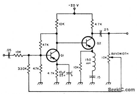
Simple audio filter provides about 20-dB gain at bandwidth of 80 Hz Bandwidth can be narrowed tolimits of unintelligibility by adjusting 10K pot.Input is plugged into phone jack of receiver, and headphones are connected to output. Transistors are SK3004 or equivalent.-Circuits, 73 Magazine, Jan.1974 p 125. (View)
View full Circuit Diagram | Comments | Reading(979)
ACTIVE_CW_FILTER
Published:2009/7/2 5:17:00 Author:May
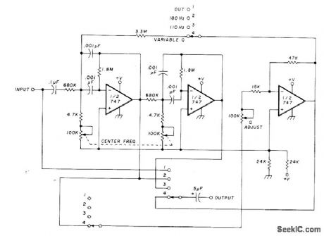
Modifications made on MFJ Enterprises OWE-2 active audio filter per mit maximum flexibility. Circuit provides fixed bandwidth of 180 or 110 Hz centered on 750 Hz, or optional variable bandwidth for which center frequency can be adiusted in range of 280 to 1590 Hz.-H. M. Berlin, Increased Flexibility for the MFJ Enterprises CW Filters, Ham Radio, Dec. 1976, p 58-60. (View)
View full Circuit Diagram | Comments | Reading(2014)
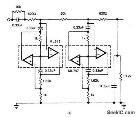
10_Hz_HIGH_PASS
Published:2009/7/2 5:13:00 Author:May
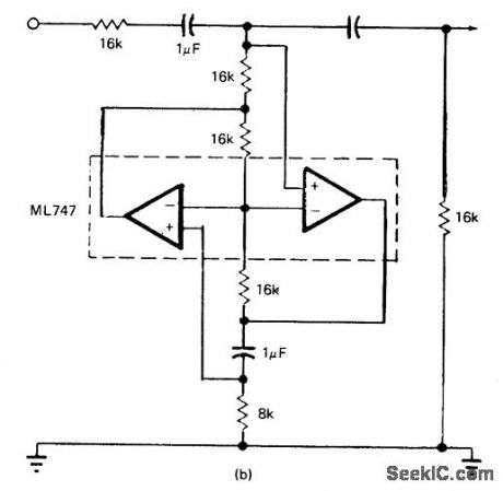
Equiterminated Butter-worth high-pass ladder filter has corner frequency of 10 Hz and output impedance level of 16K. Opamps are matched pair in single ML747 package. Article covers design procedure based on use of generalized impedance converters and gives frequency response curve.-L. T. Burton and D. Treleaven, Active Filter Design Using Generalized Impedance Converters, EDN Magazine,Feb. 5,1973,p 68-75. (View)
View full Circuit Diagram | Comments | Reading(1156)
THREE_LOUDSPEAKER_CROSSOVERS
Published:2009/7/2 5:12:00 Author:May
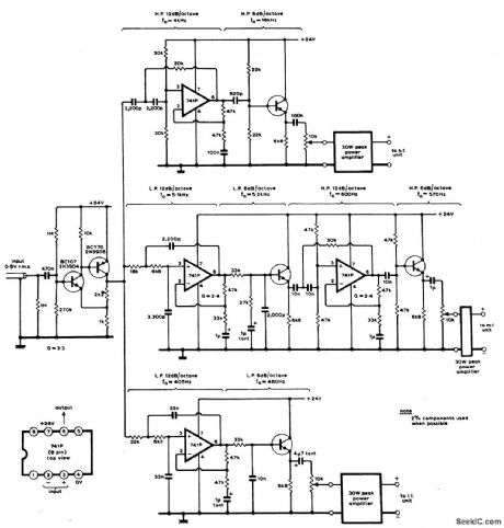
Active filter network splits AF input into three frequency bands each feeding separate 30-W power amplifier. Design allows adjustment of any part of frequency characteristic to any desired level and gives choice of slopes in any part of frequency band. Article gives design equa-tions and construction details. PNP transistors can be BCY70, BCY71, BCY72, or 2N3906. Article also gives circuit of suitable 30-W amplifier.-D. C.Read, Active Filter Crossover Networks, Wireless World, Dec.1973, p 574-576. (View)
View full Circuit Diagram | Comments | Reading(973)
60_Hz_NOTCH_FILTER
Published:2009/7/2 5:10:00 Author:May
Design is based on passband gain of 3 and O of 6. Resistors can be 5%.Opamps can be 741. Notch response is obtained by subtracting output signal of bandpass filter from its input signal whh R6.-H, M. Berlin, Design of Active Filters, with Experiments, Howard W. Sams, Indianapolis, IN, 1977, p 155. (View)
View full Circuit Diagram | Comments | Reading(2953)
TRACKING_LINE_FREQUENCY_FILTER
Published:2009/7/2 4:14:00 Author:May
Improvements in commutating RC network filter extend dynamic range without sacrificing signal bandwidth, for reducing interference at fundamental of power-line frequency and harmonics up to fifth. Although values in circuit are for British 50-Hz mains frequency, circuit can readily be adapteU for 60-Hz rejection. Operation involves commutating 16 capacitors electroni.cally at 16 times line frequency, Article gives one method of doing this, by driving two 8-way multiplexors alternately. Each multiplexec has eight MOSFETg, each switched on in turn by consecutive input clock pulses. Circuit details, design equations, and performance graphs are given Three-position swith gives choice of filer characteristics.-K. F. Knott and L. Unsworth, Mains Rejection Tracking Filter, Wireless World,Oct.1974, p 375-379. (View)
View full Circuit Diagram | Comments | Reading(961)
LOW_PASS_DIGITAL_FILTER
Published:2009/7/2 4:15:00 Author:May
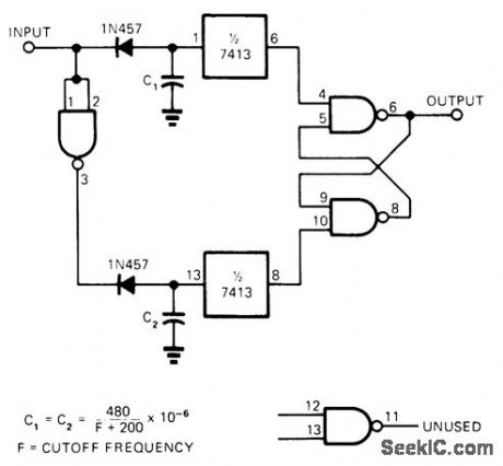
Used to retrieve pulse train data from noisy signal line. Filtering is achieved with SN7400 quad two-input NAND gate, SN7413 dual four-input Schmitt trigger, two diodes, and two capacitors. One gate of SN7400 is used as inverter driving pulse delay operating on negative-going transition of input pignal. Other Schmitt trigger, diode, and capacitor provide delay on positive-going transition. Any additional pulses occurring during delaycirouit time-out resets delay time without affecting output.-T. H. Haydon. Low-Pass Digital Filter. EDN Magazine. Nov. 20. 1973. p 85. (View)
View full Circuit Diagram | Comments | Reading(1872)
MULTIPLE_FEEDBACK_BANDPASS_FILTER
Published:2009/7/2 3:22:00 Author:May
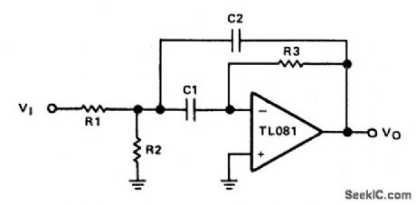
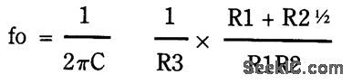
The op amp is connected in the inverting mode. Resistor R3 from the output to the inverting input sets the gain and current through the frequency-determining capacitor, C1. Capacitor C2 provides feedback from the output to the junction of R1 and R2.C1 and C2 are always equal in value. Resistor R2 may be made adjustable in order to adjust the center frequency which is determined from:When designing a filter of this type it is best to select a value for C1 and C2, keeping them equal. Typical audio filters have capacitor values from 0.01,μF to 0.1,μF which will result in reasonable values for the resistors. (View)
View full Circuit Diagram | Comments | Reading(0)
| Pages:11/21 1234567891011121314151617181920Under 20 |
Circuit Categories
power supply circuit
Amplifier Circuit
Basic Circuit
LED and Light Circuit
Sensor Circuit
Signal Processing
Electrical Equipment Circuit
Control Circuit
Remote Control Circuit
A/D-D/A Converter Circuit
Audio Circuit
Measuring and Test Circuit
Communication Circuit
Computer-Related Circuit
555 Circuit
Automotive Circuit
Repairing Circuit