
Filter Circuit
Index 2
DZW75-48/5050II high frequency rectifier filter circuit
Published:2011/12/4 20:45:00 Author:May | Keyword: high frequency reetifier, filter
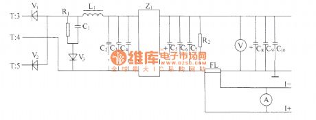
Alternating positive and negative pulse voltage of high-frequency transformer T's secondary induction is rectified by the full-wave rectifier composed of high-power high frequency switching diodes V1,V2, then it is smoothed filtered by L filter composed of inductor and capacitors C2, C3, C4 and Z1 power filter, then it gets 48V volts d.c. output with met the index high and low frequency noise requirements at output end. Impulse width determines the height of output voltage directly. Impulse width is wide, and output voltage is high, impulse width is narrow, output voltage is low. The output end is connected a voltmeter in order to measure display output volts d.c. R2 is leak resistor, and FL is current divider.
(View)
View full Circuit Diagram | Comments | Reading(2622)
DZW75-48/50(50II) high frequency rectifying filtering circuit
Published:2011/11/23 1:27:00 Author:May | Keyword: high frequency rectifying, filtering

Positive and negative alternation pulse voltage of high frequency transformer T’s secondary induction pass full wave rectifier composed of high frequency switching diodes V1, V2, then pass L power line filter composed of L1 inductor and capacitor C2, C3, C4 and Z 1 :power supply filter and other smoothing filters,then the output end gets 48V DC voltage output with high and low frequency noise to meet the index demand. The pulse width isdirectly decided bythe output voltage. When the pulse width is wide, the output voltage will be high; if the pulse width is narrow, output voltage islow. In order to measureanddisplay output DC voltage, we can parallel connect a voltmeter in output end. R2 is the leak resistor. FL is thecurrent divider. The voltage value in the justify of FL also can be uses as output current sampling signal and itcan besent to stabilize voltage and limit current. R1, C1 and V3 make up the RCD absorber circuit to absorb overshoot voltage of secondary. (View)
View full Circuit Diagram | Comments | Reading(679)
π type filter circuit composed of ISO122/124
Published:2011/11/9 21:53:00 Author:May | Keyword: filter
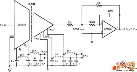
The diagram is π type filter circuit composed of ISO122/124. ISO122/124 internal osicillator set the modem frequency at 500KHz. In order to suppressthe noise from DC/DC convertor, ituses π type filter composed of inductors and capacitors wave filtering at every power source end. After wave filtering, ISO122/124 output end's 500KHz ripples are suppressed to 20mV, then it uses low-cost OPA602 ( or OPA237) to make up two pole low-pass filter forfurther wave filtering, and the two pole low-pass filter cutoff point is 100KHz.
(View)
View full Circuit Diagram | Comments | Reading(1340)
Single or dual power quad op-amp with high input impedance circuit
Published:2011/9/14 21:01:00 Author:John | Keyword: Single or dual power quad op-amp
CF14753 is classified into CMOS operational amplifiers. It has four high-performance op-map modules, which is quite similar to MC14753. It is equiped with phase compensation device inside. It is mainly used for a variety of analog computing circuits, AC amplifiers, low frequency waveform generators and active filters and so on. It can also be composed of chopper amplifiers and automatic zero op-amp. Substitutions or direct models are CFl4573, 5G14573, MCl4573, CHl4573 and CAl4573 and so forth.
(View)
View full Circuit Diagram | Comments | Reading(1233)
Thermocouple temperature system simulation circuit
Published:2011/9/12 21:17:00 Author:John | Keyword: Thermocouple temperature system
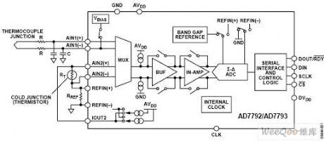
Temperature on the cold junction is measured by the use of resistance temperature detectors (RTD) or thermistor (shown in the RT). The resistance for these two devices changes along with the temperature. On-chip current source provides the required excitation current. In this measurement configuration, a ratio is used, that is, the ADC reference voltage source and the precision resistor use the same excitation current. A ratio configuration enables the temperature measurement on the cold junction to be independent from the excitation current, because the change of excitation current can lead to same changing amount of the voltage generated by the sensor and that generated by the precision resistor. Therefore, there is no effect on analog digital conversion. (View)
View full Circuit Diagram | Comments | Reading(2230)
The Power Frequency Noise Filter Circuit (μPC822)
Published:2011/9/6 4:44:00 Author:Felicity | Keyword: Power Frequency Noise Filter
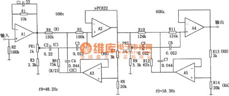
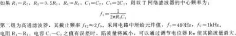
The circuit is a double-T filter to filter out the mixed 50Hz (or 60Hz) power frequency noise when amplifying (such as sensor )weak signal.If only using the RC components to comprise similar filter, usually the value of Q is low and has the attenuation performance of the bandwidth performance .Adopting operational amplifier and positive feedback can increase the value of Q. Supposing that the values of Q is Q', then Q'=Q/(1一K),and K=RA/(RA+RB).Tuning the coefficient Q can increase the value of Q.And the resonant frequency of the circuit is fo=1/2πRC and the positive feedback components are R/2 and 2C. (View)
View full Circuit Diagram | Comments | Reading(2061)
CF1456 Double-Power General-Type Single-Supply Amplifier Circuit Diagram
Published:2011/9/7 0:47:00 Author:Vicky | Keyword: Double-Power General-Type Single-Supply
CF1456 series operational amplifier is a inner-complementing type high-gaining amplifier. Its input current is relatively low, and power dissipation is very low. There is zero-setting end exteriorly, which has short-circuit protection and over-voltage protection functions. It is available in summing amplifier and intefrator. The analog types or substitutions are CFl556MT、CF1456CT、CF1556MD、CF1456CD、CF1556MJ、CF1456CJ、CF1456CP etc. (View)
View full Circuit Diagram | Comments | Reading(621)
High resolution quadruple frequency subdivision circuit diagram
Published:2011/9/6 21:03:00 Author:Vicky | Keyword: high resolution, quadruple frequency , subdivision circuit
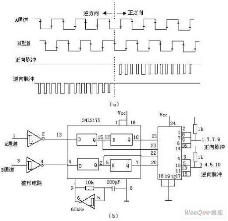
The above picture is a circuit of quadruple frequency which can not only avoid the false pulse, but also improve the high resolution. Here, it adopts a memorable D-type trigger and clock generator circuit. As shown in picture 4, every channel has two D-type triggers in serial, so that, during the interval of the clock pulse, the two Q ends (such as the corresponding pin2 and pin7 of 74LS175 in channel B) retain the input state of the former two periods. If the two are the same, it means there is no change in the clock interval; otherwise, the change of direction can be judged by the relationship within, and therefore the output pulse of forward direction or reverse direction is generated. (View)
View full Circuit Diagram | Comments | Reading(988)
Diagram of two filter circuits used for AM broadcast interference
Published:2011/9/6 21:00:00 Author:Vicky | Keyword: filter circuit, AM broadcast interference
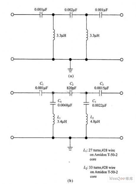
AM reflecting filter in the picture (a) can be composed of common disk-type ceramic capacitor, silver capacitor, and Panasonic V series polyester capacitor. Though it is better to use digital capacitance meter or capacitance bridge to match with, an allowance of 5 percent for the component can still meet the satisfaction. If silver capacitance is used, it is better to use 1000pF (0.001ptF) capacitance, and the 0.002ptF capacitance can use two 0.001pF capacitances in serial (C1 and C3)。 The average inductance of the circuit is 3.3μH. It can use either isolated regular magnetic chip inductance or non-isolated annular magnetic chip inductance. (View)
View full Circuit Diagram | Comments | Reading(945)
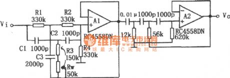
24dB/ octave Low-pass Filter Circuit Composed of the Same Parameters (μPC882)
Published:2011/8/10 9:54:00 Author:Felicity | Keyword: Same Parameters, Low-pass Filter
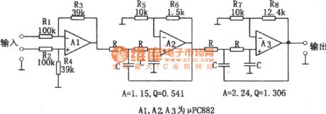
The circuit is 24dB/ octave low-pass filter composed of the filter components of the same parameters. To get the required Q, the open-loop gain of the operational amplifier should be above 1 and the input stage become a 1/2.57 attenuator. This circuit’s feature is the resistance R and capacitor C with decided cutoff frequency fc can reach the same parameters. The parameters of the circuit are determined by cutoff frequency, fc=1/(2πRC) ,and the resistance range is between several to several hundred kΩ and the capacity is above several hundred pF.
(View)
View full Circuit Diagram | Comments | Reading(2328)
-18dB/octave Active Low-pass Filter Circuit (RC4558DN)
Published:2011/8/10 7:19:00 Author:Felicity | Keyword: Active, Low-pass Filter
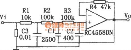
The -18dB/octave active low-pass filter circuit is shown in the figure. This circuit consists of -6dB passive filter and -12dB/octave active filter and the whole circuit is a -18dB/octave active low-pass filter. The passive filter consists of R1 and C3, the active filter consists of R2, R3, C1, C2 and operational amplifier.
(View)
View full Circuit Diagram | Comments | Reading(4465)
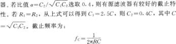
Q and Frequency Adjustable Narrow Band Filter (741)
Published:2011/8/10 7:38:00 Author:Felicity | Keyword: Q and Frequency Adjustable, Narrow Band Filter
The circuit is an active Q and frequency adjustable narrow band filter. It adopts the form of Wien bridge positive feedback ,but the loop gain is under 1.The character of this circuit is that adjusting Q has no effect on center frequency, because Q only depends on the gain of the circuit.When the gain is 600,Q is 2000; and when the gain is 140,Q is 30. And in the ordinary Wien bridge oscillator, for non-inverting terminal, the gain of the amplifier must above 3 to oscillate, but in this circuit the gain of the amplifier is below 3. (View)
View full Circuit Diagram | Comments | Reading(1226)
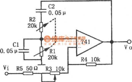
The Circuit of Active High-Pass Filter With Sharp Cutoff Performance (RC4558DN)
Published:2011/8/10 7:58:00 Author:Felicity | Keyword: Active, High-Pass Filter, Sharp Cutoff Performance
Active high-pass filter with sharp cutoff performance is shown in this circuit. To improve the frequency characteristic around cutoff frequency fc of high-pass filter, in this circuit a high-pass filter and a band-stop filter are connected in series to improve the frequency characteristic of the high-pass filter. The first stage in this circuit is band-stop filter consists of double-T network and load resistance R4, composing band-pass filter that gain descends in low frequency. To increase the value of Q, there is a bootstrapping at the end of the double-T network. (View)
View full Circuit Diagram | Comments | Reading(2960)
Single-peak Filter Circuit Composed of One Operational Amplifier
Published:2011/8/10 8:35:00 Author:Felicity | Keyword: Single-peak Filter, Operational Amplifier
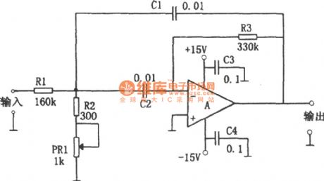
The single-peak filter composed of one operational amplifier is shown in the figure. This circuit only uses one operational amplifier and a few components to build up filter circuit that has the same performance composed of LC components. The resonant frequency can be easily tuned without changing the circuit gain. This circuit uses potentiometer PR1 to tune the resonant frequency. When the value of PR1 varies from minimum to maximum, the resonant frequency tuned range is 1580Hz, and the circuit gain hardly changes. (View)
View full Circuit Diagram | Comments | Reading(1367)
Capacitance Filter Circuit
Published:2011/8/23 23:41:00 Author:Robert | Keyword: Capacitance, Filter
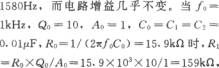
After the rectifier the output voltage would change to be DC voltage, but the voltage waveform fluctuate largely. In order to get the smoothing DC voltage waveform, it needs to use the filter method. The filter method is always using the performance of the reactance feature from the reactance components to the AC signals. And it would connect the capacitance or inductance to the load resistance to make up the filter circuit.The picture shows the single-phase half-wave rectifier capacitance filter circuit and working waveform. From the picture (a), when the circuit is not connectted to the capacitance C, the output voltage would be shown in dotted line of picture (b). (View)
View full Circuit Diagram | Comments | Reading(779)
Inductance Filter Circuit
Published:2011/8/23 23:41:00 Author:Robert | Keyword: Inductance, Filter
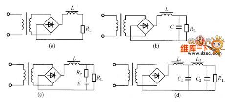
The capacitance filter circuit's output internal resistance is very big. When the RL changing, the port voltage would also change. Also, the when current-limiting diode is conducted, the impact current is very large which would effect its life. The resistance is small but its AC impedance is very large, that is the inductance filter circuit. So it could use the inductance coil for DC voltage, which is the inductance filter. The picture shows some inductance filter circuit.
The picture shows the inductance filter circuit.
The picture (a) shows the single inductance filter circuit. Its weakness is: generally its filter coefficient (the filter coefficient is the first harmonic voltage amplitude ratio between the filter circuit input port and output port) could only be made under several dozens. (View)
View full Circuit Diagram | Comments | Reading(857)
45_kHz_LOW_PASS_STATE_VARIABLE_FILTER
Published:2009/7/14 20:39:00 Author:May
Used In precision telephone-network active equalizer Camping value is 0.082, which requires 1% components. For high pass, take out-put from first opamp; for band pass, take output from second opamp.-D. Lancaster, Active-Filter Cookbook, Howard W Sams, Indianapolis, IN, 1975, p 147. (View)
View full Circuit Diagram | Comments | Reading(1752)
TOUCH_TONE_BAND_REJECT_FILTER
Published:2009/7/14 8:34:00 Author:May
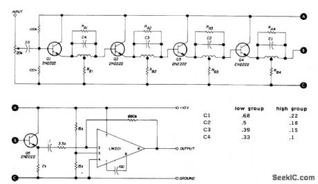
Cascaded notch filters with active limiter at output provide 20-dB attenuation of either low (697-941 Hz) or high (1209-1633 Hz) groups of tones, as aid to decoding for repeater control functions. All coils are 88-mH toroid. RA is between 5600 and 22,000 ohms, and RB is 1000 to 3000 ohms. Article gives tuning procedure for selecting resistor values and adjusting toroids so each stage rejects different tone in its band.-B. Bretz, Multi-Function FM Repeater Decoder, Ham Radio, Jan. 1973, p 24-32. (View)
View full Circuit Diagram | Comments | Reading(1393)
LOW_COST_IR_FILTER
Published:2009/7/14 7:26:00 Author:May
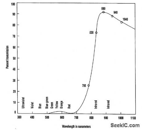
When exposed to “cool white” fluorescent light for 5 s, the color negative (using Kodacolor 100 ASA film) produced after the developing process exhibits a sharp cutoff at about 830 mm. This is perfect for many IR LEDs and other IR devices. (View)
View full Circuit Diagram | Comments | Reading(859)
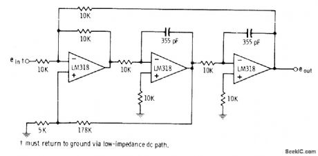
RECEIVE_FILTER
Published:2009/7/14 4:30:00 Author:May
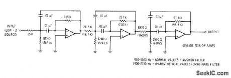
Used as prefilter having controlled group-delay distortion, ahead of receiving modem in data transmission system. Values shown are for 950-1400 Hz answer filter. For 1900-2350 Hz originate filter, change critical values to those given in parentheses. -D. Lancaster, TV Typewriter Cookbook, Howard W. Sams, Indianapolis, IN, 1976, p 180-182. (View)
View full Circuit Diagram | Comments | Reading(902)
| Pages:2/21 1234567891011121314151617181920Under 20 |
Circuit Categories
power supply circuit
Amplifier Circuit
Basic Circuit
LED and Light Circuit
Sensor Circuit
Signal Processing
Electrical Equipment Circuit
Control Circuit
Remote Control Circuit
A/D-D/A Converter Circuit
Audio Circuit
Measuring and Test Circuit
Communication Circuit
Computer-Related Circuit
555 Circuit
Automotive Circuit
Repairing Circuit