
Filter Circuit
Index 3
BANDPASS_ORIGINATE_FILTER
Published:2009/7/14 4:19:00 Author:May
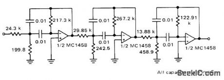
Provides gain of over 15 dB between 1975 and 2275 Hz, to accept 2025-2225 Hz, signals of low-speed modem system using Motorola MC6860 IC,-J. M. DeLaune, “Low-Speed Modem System Design Using the MC6860,”Motorola, Phoenix, AZ、1975, AN-747, p13 (View)
View full Circuit Diagram | Comments | Reading(808)
TRANSISTOR_AS_SMOOTHING_FILTER
Published:2009/7/14 4:16:00 Author:May
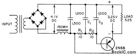
Single junction transistor in liter network of low-voltage power supply permits use of smaller fiber capacitors and chokes. Used in calibrating d-c meters up to 1 amp, at which residual peak-to-peak ripple values are 0.0015 amp and 0.005 v.-F. Oakes and E. W. Lawson, Transistor Filters Ripple, Electronics, 31:15, p 95. (View)
View full Circuit Diagram | Comments | Reading(942)
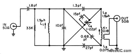
GENERAL_FILTER
Published:2009/7/14 4:14:00 Author:May
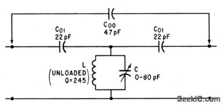
Bridging conventional bandpass filter with single capacitor C00 converts to general fiber having both sharp pass and reject behavior at adjacent frequencies. For values shown, bandpass occurs at 20 Mc and peak rejection frequency is 19.15 Mc.-R. Kurzrok, Single Component Changes Bandpass into General Filter, Electronics, 39:8, p 95-96. (View)
View full Circuit Diagram | Comments | Reading(877)
TRANSISTORIZED_MAGNETOSTRICTION_BAND_PASS_FILTER
Published:2009/7/14 4:14:00 Author:May
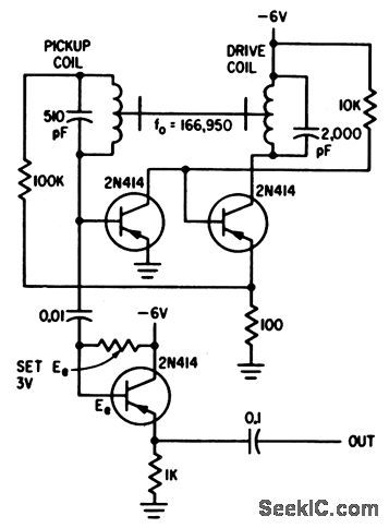
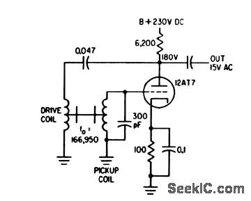
Three transistors and filter give stable fixed-frequency oscillator, with over all gain of 20 db and maximum linear out-put of 1 v rms.-E. J. Neville, Jr., Designing Magnetostriction Filters, Electronics, 33:51, p 88-89. (View)
View full Circuit Diagram | Comments | Reading(1035)
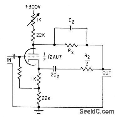
CASCADED_HIGH_AND_LOW_PASS_A_F
Published:2009/7/14 4:13:00 Author:May
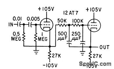
Slope can be any desired multiple of 12 db per octave, with insertion loss less than 2 db.Corner frequencies are 200 radians per sec (32 cps) and 40,000 radians per sec (6,370 cps).-W. D. Fryer, How to Design Low Cost Audio Fillers, Electronics, 32:15, p 68-70. (View)
View full Circuit Diagram | Comments | Reading(827)
WIEN_BRIDGE_FILTER
Published:2009/7/14 4:13:00 Author:May
Does not have high Q but provides good rejection (40 db attenuation with 1 % tolerance components and 60 db with 0.1% tolerance components).-J. K. Goodwin, Wien Bridge Forms Rejection Filter, Electronics, 32:1, p 58-59. (View)
View full Circuit Diagram | Comments | Reading(0)
DYNAMIC_NOTCH_FILTER
Published:2009/7/14 4:12:00 Author:May
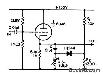
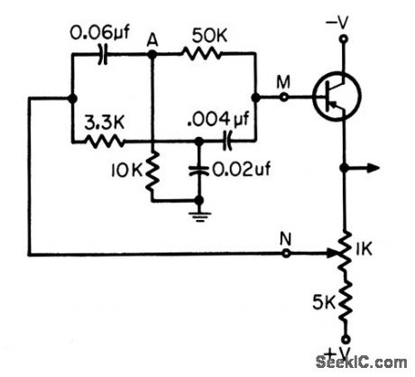
Will trap out 10-Mc noise while passing 10.Mc signal in heterodyne frequency convertor used to extend measurement range of 10-Mc counter. Operation is based on difference in level of noise and desired signal. Dynamic action of filter nulls out low-level noise, but filter disappears in presence of desired high-level signal. -H. T. McAleer, Dynamic Notch Filter, FEE, 10:9, p 90-91. (View)
View full Circuit Diagram | Comments | Reading(932)
LATTICE_COUPLING_OF_DOUBLE_TUNED_FILTER
Published:2009/7/14 4:11:00 Author:May
Permits adjusting coupling between input and output resonant circuits to com pensate for stray reactances and variations in component values. Used in 30.Mc i-f amplifier requiring 1-Mc bandwidth. One side of variable capacitor is grounded, per mitting convenient mechanical design.-J. H. Grindon, Lattice Coupling of Resonant Circuits, EEE, 13:6, p 53-55. (View)
View full Circuit Diagram | Comments | Reading(747)
TWIN_T_400_CPS_FILTER
Published:2009/7/14 4:11:00 Author:May
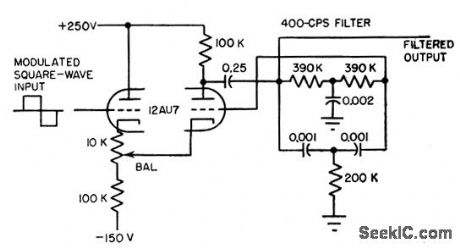
Used with modulators lo increase signed-noise ratio. Filter is tuned to 400 cps, and eliminates other frequencies by feeding them back. Q of fiber is 6. Output is low-distortion sine wave in phase with input. Frequency regulation of cattier signal should be barter than 1% or liter will introduce phase shift.-L. S. Klivans, Modulators for Automatic Control Systems, Electronics, 31:1, p 82-84. (View)
View full Circuit Diagram | Comments | Reading(907)
ACTIVE_800_CPS_PARALLEL_T_FILTER
Published:2009/7/14 4:10:00 Author:May
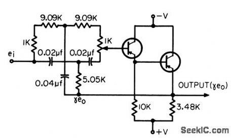
Potentiometer adjusts amount of rejection to compensate for tolerances of components. Second emitter-follower provides lower output impedance so feedback to network is more effective in sharpening notch of filter characteristic and in decreasing phase shift around null frequency. Used in servo sys terns.-T. Mollinga, Actiye Parallel-T Net.works, EEE, 14:4, p 93-98, (View)
View full Circuit Diagram | Comments | Reading(925)
TRIPLE_TUNED_90_OHM_INPUT
Published:2009/7/14 4:10:00 Author:May
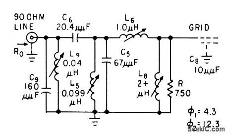
Article gives design procedure. Example shown passes signals between 55 and 65.5 Mc.-R. B.Hirsch, How to Design Bandpass Triples, Electronics, 32:34, p 41-44. (View)
View full Circuit Diagram | Comments | Reading(773)
VARIABLE_BANDWIDTH_848_KC_CRYSIAL_FILTER
Published:2009/7/14 4:09:00 Author:May
High-Q unbalanced crystal filter is easy to adjust over appreciable frequency range,Can be used in f-m oscillators, signal generators, and i-f amplifiers, as well as in variable-bandwidth filters.-J. C. Seddon, Stable Crystal Filter is Parallel Resonant, Electronics, 31:11, p 155-156. (View)
View full Circuit Diagram | Comments | Reading(775)
800_CPS_OSCILLATOR_WITH_PARALLEL_T_FILTER
Published:2009/7/14 4:08:00 Author:May
R-C network in feedback loop determimes frequency of oscillation.-T. Mollinga, Active parallel-T Networks, EEE, 14:4, p 93-98. (View)
View full Circuit Diagram | Comments | Reading(767)
LOW_PASS_FILTER
Published:2009/7/14 4:07:00 Author:May
Unwanted short pulses from shot noise in celestial guidance photo-multiplier are removed by active Low-pass filter having constant phase shift over pass band. Active filter avoids bulky inductors and impedance-matching problems. Filter is modified 6th-order Bessel type, coiled a Paynter filter.-R. L. Lillestrand, J. E. Carroll, and J. S. Newcomb, Automatic Celestial Guidance, Part 2: New Challenge to Designers' Ingenuity, Electronics, 39:7, p 94-105. (View)
View full Circuit Diagram | Comments | Reading(0)
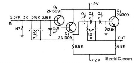
7_CPS_ACTIVE_BANDPASS
Published:2009/7/14 4:07:00 Author:May
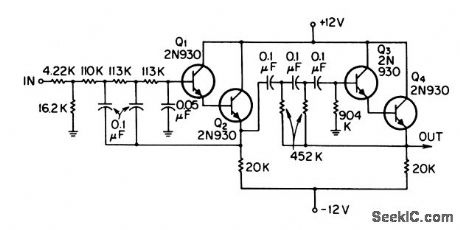
Band width is 1.6 cps for center frequency of 7 cps.-T. Mollinga, Active Bandpass Filers, EEE, 14:8, p 115-119. (View)
View full Circuit Diagram | Comments | Reading(795)
800_CPS_ACTIVE_BANDPASS
Published:2009/7/14 4:06:00 Author:May
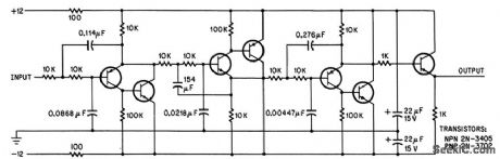
Provides bandwidth of 13 cps. Maximum gain is 24 db, and divider at input reduces this to 0 db. Selectivity at 3-db points is 72 db/octave.-T. Mollinga, Active Bandpass Fillers, EEE,14:8, p 115-119. (View)
View full Circuit Diagram | Comments | Reading(788)
ZOBEL_HIGH_PASS_FILIER
Published:2009/7/14 4:03:00 Author:May

Both examples give at least 40 db attenuation below 2,740 cps when inserted between 600-ohm source and load resistances.-K. Lichtenfeld, Method for Simplifying Filter Design, Electronics, 33:21, p 96-99. (View)
View full Circuit Diagram | Comments | Reading(1417)
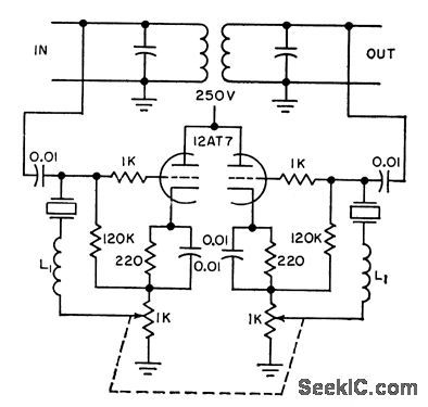
TRIODE_MAGNETOSTRICTION_BANDPASS_FIL_TER
Published:2009/7/14 4:02:00 Author:May
Practical range is from 45 to 300 kc. When filler is used with triode, it serves as stable fixed-frequency oscillator in telemetry command receiver.-E. J. Neville, Jr., Designing Magnetostriction Filters, Electronics, 33:51, p 88-89. (View)
View full Circuit Diagram | Comments | Reading(877)
325_KC_BRIDGED_T_FILTER
Published:2009/7/14 4:02:00 Author:May
Used in magnetometer having large amounts of odd harmonics and only feeble second harmonk at secondary of sensing probe. Permits ampli-flying only second harmonic, without excessive phase shift.-F. Voelker, Magnetometer Makes Continuous Measurements, Electronics, 31:11, p 152-154. (View)
View full Circuit Diagram | Comments | Reading(696)
LOW_PASS_SUBAUDIO_FILTER
Published:2009/7/14 4:01:00 Author:May
Gives flat frequency response from d-c to 1-cps cutoff, attenuation slope of 15 db per octave, near zero insertion loss, and good temperature stability.-R. C. Onstad, Low-Pass Filter for Subaudio Frequencies, Electronics, 33:3, p 88-90. (View)
View full Circuit Diagram | Comments | Reading(813)
| Pages:3/21 1234567891011121314151617181920Under 20 |
Circuit Categories
power supply circuit
Amplifier Circuit
Basic Circuit
LED and Light Circuit
Sensor Circuit
Signal Processing
Electrical Equipment Circuit
Control Circuit
Remote Control Circuit
A/D-D/A Converter Circuit
Audio Circuit
Measuring and Test Circuit
Communication Circuit
Computer-Related Circuit
555 Circuit
Automotive Circuit
Repairing Circuit