
Filter Circuit
Index 16
HIGH_PASS_ACTIVE_FILTER
Published:2009/6/19 1:59:00 Author:May
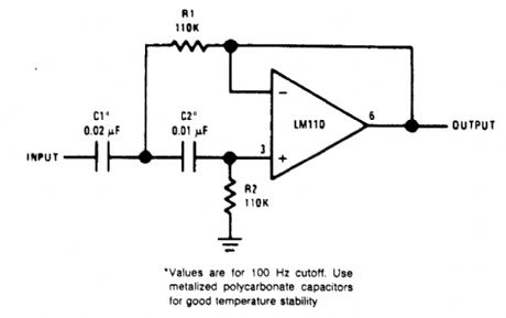
View full Circuit Diagram | Comments | Reading(1)
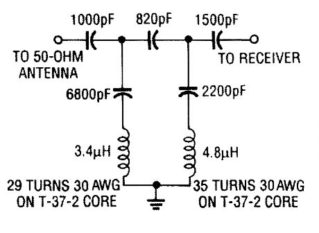
SHORTWAVE_RECEIVER_IF_FILTER
Published:2009/6/19 1:58:00 Author:May
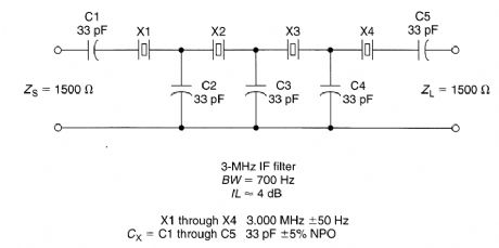
An inexpensive filter can be made from microprocessor crystals. This filter has 700 Hz BW (3 dB) and has a flat response (<1 dB) for about 400 to 500 Hz. Although a 3-MHz crystal was used, any frequency from 2 to 15 MHz (using fundamental crystal) should work, with appropriate scaling of components. Crystal resonant frequencies should match within 20% and preferably 10% of expected bandwidth (which is narrower as Cx increases. Impedance is reduced with wider bandwidths. (View)
View full Circuit Diagram | Comments | Reading(815)
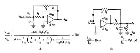
COMBINATION_FILTER
Published:2009/6/19 1:57:00 Author:May
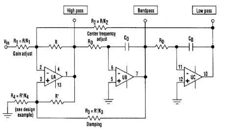
The classic state variable two-integrator filter is known for its insensitivity to component varia-tions, and its ability to provide three separate simultaneous outputs-low pass, high pass, and bandpass.Typically, a quad op amp is used to implement the state-variable filter. The classic configuration uses two integrating amplifiers, a filter input amplifier, and a filter feedback amplifier.The design described here combines both input and feedback amplifiers into one adder/subtrac-tor amplifier, achieving a three op-amp filter design (see the figure). (View)
View full Circuit Diagram | Comments | Reading(1840)
SECOND_ORDER_VOLTAGE_CONTROLLED_FILTER
Published:2009/6/19 1:55:00 Author:May
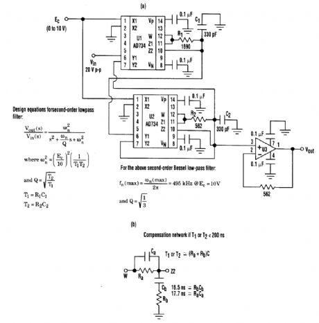
Desirable second-order voltage-controlled low-pass filter response can be achieved with this voltage-controlled filter (A). By using low-distortion, wide-bandwidth multipliers, it achieves higher cutoff frequencies than sv(itched-capacitor filters. If the circuit's RC network has a time constant less than 200 ns, it should be replaced by a lag compensator network (B). (View)
View full Circuit Diagram | Comments | Reading(768)
HIGH_PASS_FILTER
Published:2009/6/19 1:54:00 Author:May
This high-pass filter will attenuate AM stations by 40 dB. Its low-frequency cutoff is about 2.2 MHz. This filter is useful for SW listening in areas of high AM radio signal strength. (View)
View full Circuit Diagram | Comments | Reading(1049)
ACTIVE_BANDPASS_FILTER_CIRCUIT
Published:2009/6/19 1:52:00 Author:May
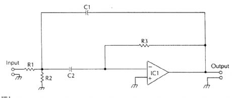
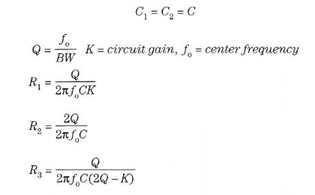
In this circuit, (View)
View full Circuit Diagram | Comments | Reading(726)
SALLEN_KEY_HIGH_PASS_FILTER
Published:2009/6/19 1:50:00 Author:May
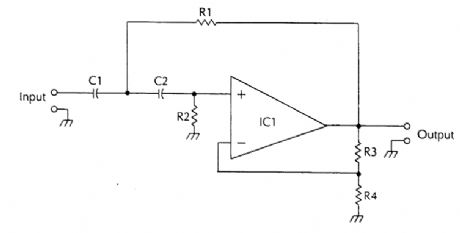

R3 and R4 set the circuit galn (View)
View full Circuit Diagram | Comments | Reading(801)
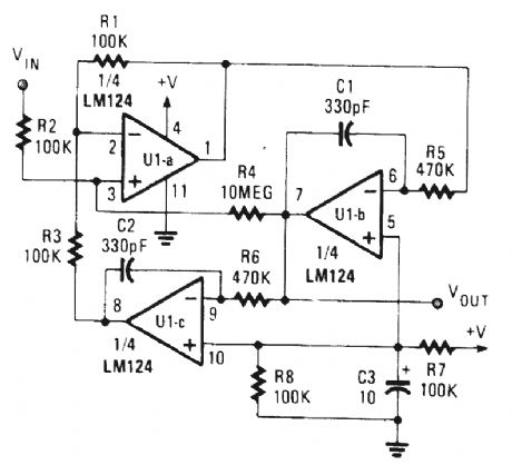
STAET_VARIABLE_FILTER
Published:2009/6/19 1:49:00 Author:May
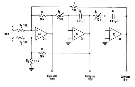
The state variable filter shown consists of only three op amps and a few passive components. It provides several key features. These include the ability to simultaneously provide low-pass, high-pass, and bandpass filter functions, and adjust bandwidth in a wide range by changing the values of Cf and Rf. The device also is easy to tune and simple to congtruct, while the quality factor (Q) of each filter is independent of each other. (View)
View full Circuit Diagram | Comments | Reading(1011)
CW_AUDIO_FILTER
Published:2009/6/18 2:59:00 Author:May
A high-performance passive filter. The center frequency is 700 Hz; -3-dB bandwidth is 200 Hz. (View)
View full Circuit Diagram | Comments | Reading(1045)
45_MHz_IF_AMPLIFIER_WITH_CRYSTAL_FILTER
Published:2009/6/18 2:29:00 Author:May
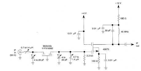
A 40673 dual-gate MOSFET is matched to a crystal filter at 45 MHz. The filter impedance is around 2kΩ. The + 4-V source can be made variable for gain control (about +4 to -4V.) (View)
View full Circuit Diagram | Comments | Reading(1199)
1_kHz_TONE_FILTER
Published:2009/6/16 21:29:00 Author:May
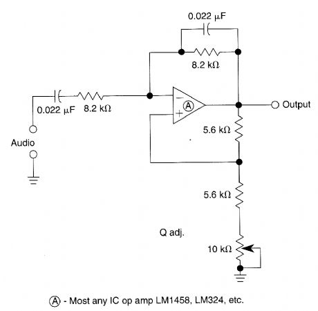


The Wien-bridge based filter has a variable bandwidth and a center frequency of 900 Hz. The circuit will oscillate if the 10-kΩ pot is set too low. (View)
View full Circuit Diagram | Comments | Reading(797)
FULL_WAVE_RECTIFIER_AVERAGING_FILTER
Published:2009/6/16 21:27:00 Author:May
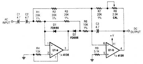
The input signal is rectified by D1 and D2 Op amp U1-a,and fed to output amp U2 R8 is set for correct circuit calibration. (View)
View full Circuit Diagram | Comments | Reading(768)
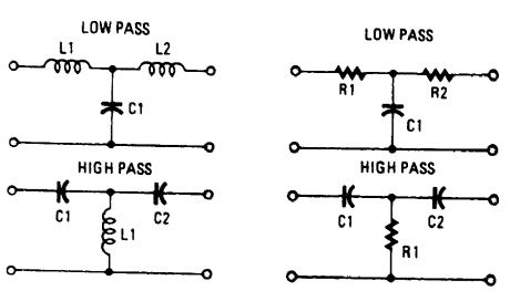
PASSIVE_T_FILTER_CONFIGURATIONS
Published:2009/6/16 21:19:00 Author:May
View full Circuit Diagram | Comments | Reading(814)
BI_QUAD_RC_BANDPASS_FILTER
Published:2009/6/16 21:19:00 Author:May
View full Circuit Diagram | Comments | Reading(699)
AUDIO_RANGE_FILTER
Published:2009/6/16 21:18:00 Author:May
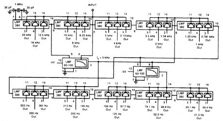
The LMF380 switched audio filter by National Semiconductor is used here to obtain a third-oc-tave filter set that covers the entire audio range. (View)
View full Circuit Diagram | Comments | Reading(759)
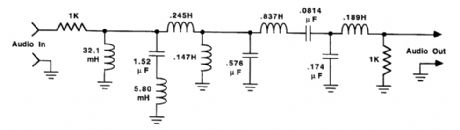
455_kHz_NARROW_BAND_IF_FILTER
Published:2009/6/16 21:14:00 Author:May
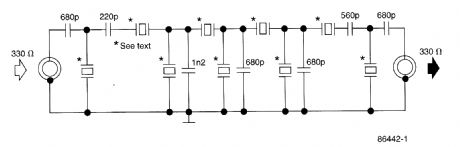
This filter uses five 455-kHz ceramic resonators. The impedance is 330Ω, the bandwidth is 800 Hz, and the ultimate rejection ≥60dB. The ceramic resonators could be replaced by crystals. (View)
View full Circuit Diagram | Comments | Reading(3265)
CURRENT_DRIVEN_SALLEN_KEY_FILTER
Published:2009/6/16 21:13:00 Author:May
The low-pass Sallen-Key filter is staple for designers because it contains few components (A).By redesigning the filter, a current to voltage conversion can be avoided when the input signal to be filtered is in current form (B). (View)
View full Circuit Diagram | Comments | Reading(745)
SIMPLE_LOW_PASSLPACTIVE_FILTER_FOR_1kHz
Published:2009/6/16 21:12:00 Author:May
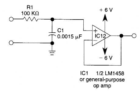
This simple filter uses an RC section for a filter element, with a voltage follower for other frequencies f3 dB = 1/6.28 R1C1 Response drops 6 dB/octave above f3 dB. (View)
View full Circuit Diagram | Comments | Reading(743)
SECOND_ORDER_LOW_PASS_FILTER_FOR_10_kHz
Published:2009/6/16 21:11:00 Author:May
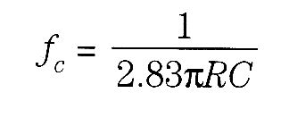
This circuit uses equal value capacitors, The cutoff frequency (fc) is (View)
View full Circuit Diagram | Comments | Reading(864)
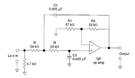
EQUAL_COMPONEHNTS_SECOND_ORDER_HP_FILTER
Published:2009/6/16 21:10:00 Author:May
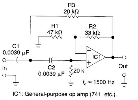

This filter circuit uses equal value components and is shown for 1500Hz.The values can be scaled for other frequencies.R=R1R2=2R1C=C1=C2 (View)
View full Circuit Diagram | Comments | Reading(720)
| Pages:16/21 1234567891011121314151617181920Under 20 |
Circuit Categories
power supply circuit
Amplifier Circuit
Basic Circuit
LED and Light Circuit
Sensor Circuit
Signal Processing
Electrical Equipment Circuit
Control Circuit
Remote Control Circuit
A/D-D/A Converter Circuit
Audio Circuit
Measuring and Test Circuit
Communication Circuit
Computer-Related Circuit
555 Circuit
Automotive Circuit
Repairing Circuit